PiDP Photo Thread: show us your setups!


Dylan McNamee
Tom - I love your machine room! I've never seen an Altair in person, so am a bit surprised how close in size the PiDP is (width and height, not depth). Here's mine, sitting next to my MacBook running the great terminal simulator "Cathode".


Norman Davie


Philipp Geyer
I'm calling in some favours on the switches because I'm not very happy with them. I'm going to see if I can get some caps printed on my colleague's 3D printer. If that works, I will provide the files and offer switches in three states (rough printed, filled and smoothed, painted and ready to glue on)
The only thing I am a little bit disappointed about with this kit is that there's no space to put the two key switches on the bottom left!
I'm not entirely sure what I'll do with my PiDP yet, it will probably sit in the corner of my project room, and I'll turn it on to let the blinkenlights sooth me occasionally
This is my first non-trivial electronics kit and the first time I've picked up my soldering iron in a number of years. Everything was so easy and just worked. I am wondering if the PiDP will have spoilt me for later projects...
Phil

Tim Goldenburg


Doug Jackson


Andrew Wasson
Well, I got mine fired up a little over a week ago (Friday July 31st) and I think everything is working as expected. This is such a well done kit!
I've keyed in some simple machine language programs to zero the accumulator and then increment it. I've run it, and stepped through as well to make sure it does what it's supposed to. I've keyed in and run the demo program that allows one to check all of the LEDs and I'll have to write some small programs to check other areas of the instruction set later. Since it's connected to my local network, I'm connecting via SSH for now. I've been considering an old-school serial terminal but for now SSH is certainly convenient. I've spent a little time playing Lunar Lander, Space Wars but I've spent the majority of my time playing Adventure; playing Adventure from my workstation and watching the light-show whenever I make a move is pretty cool!
I've cut a rectangular opening on the left side of the case, providing access to the ethernet and USB connectors. I think I'll add a figure-8 plug to the case as well for the power supply and add a small rocker to power on/off.
MODS
I didn't particularly like the way the bottom of the bank of switches overlapped the wooden case because it kept the circuit board and switch bank from being perfectly square with the case and didn't allow the faceplate to sit square against the recesses in the case. I thought about rebating the lower lip of the wooden case slightly with a small router to accommodate the switches but after some consideration, it seemed risky so I chose to measure and carefully remove the offending metal with sheet metal snips. I have several sets of snips and it required patience and the right combination of tools to get the job done. To finish the switch bank, I glued some heavy black card stock to the exposed metal tangs on the switches.
I still have to paint the switches and add my on/off switch but I think it's looking pretty fantastic at the moment.


Jamie Cox
- Cleaned off the red dots on switches
- Painted the switches with Krylon spray paint "Brown Boots". I'm happy with the color & durability.
- Painted the brass switch housings flat black with a brush. (Not terribly durable. The paint was probably intended for plastic.)
- Added Bic lighter springs under the momentary switches. I removed the spring from the Stop switch because of its function on startup.
- Used Velcro to hold the faceplate on. I glued it to screws, similar to the original magnet plan. Velcro probably needs more surface area.
- Dremel-tooled the lip of the case to allow more room for the switches and the faceplate.
- Serial terminal connected via USB-serial adapter.
Norman Davie

Harris Newman

Greg Estep
Philipp Geyer
This is the current state of my PiDP
Deposit switch flipped, all relevant switches sprung, serial port secured to the back, I'm going to unsolder the switches and replace the white plastic as the 3D printed caps didn't work out (too tall). Power plug (actually aviation microphone plug) attached to the back and 5V transformer from USB power socket glued inside. I'm still waiting on my magnets from the front and I'm toying with the idea of attaching at least one more serial port to the back in case I get the time/motivation to build a paper tape reader. I haven't blacked the switch plates yet because I'm still unsure how they're going to end up. With me taking it apart and working with it, I'm beginning to think whether it would be worth looking into how much it would cost for a replacement front panel... I may have scratched it a little.
Hopefully I will get the serial port wired in in the next few days, I have a bunch of the TTL converters, I just need to desolder one pair of USB ports to fit them...
Enough rambling for tonight, food calls
Phil

Jeremy Radwan
Jeremy Radwan

Stephen Clarke-Willson
--
You received this message because you are subscribed to the Google Groups "PiDP-8" group.
To unsubscribe from this group and stop receiving emails from it, send an email to pidp-8+un...@googlegroups.com.
To post to this group, send email to pid...@googlegroups.com.
To view this discussion on the web visit https://groups.google.com/d/msgid/pidp-8/426b3fae-7b8c-454c-b89e-455abe9d36e8%40googlegroups.com.
For more options, visit https://groups.google.com/d/optout.

Super Grover
The other two shots are the relocation of the pi to the middle of the board, using an 1/2 an old IDE cable and a male IDC 40pin connector. This means I don't have to cut the side open for the USB ports.
I'm still waiting for my USB to 4 port Serial, SD panel mount extension cable, HMDI panel mount cable, and USB panel mount that are on the slow boat from china.
I'm going to design/laser cut a black plexi back plate for the external connections (+5 , power switch, usb x 3, serial, hdmi)
The DEC computers are a bit before my time, but it has been a fun trip so far.

Bill Laing
I ask because I can't get my serial interface to work using P5 and the recomended voltage divider. I can make the RS232 interface work if I connected it directly to the Pi. I have read the post about the PCB not correctly implementing the voltage divider and have used the fix described in that post.

Obsolescence
On Monday, September 28, 2015 at 12:50:05 AM UTC+2, Bill Laing wrote:
How did you connect the DEC terminal?
I ask because I can't get my serial interface to work using P5 and the recomended voltage divider.
That must be because indeed, like your other post suggests, Mark's photo show the high and low ohm resistor the wrong way around leaving a 1.7V signal. But the fix of soldering the bottom resistor's lead to the lead of the middle resistor is the correct fix to my PCB trace blunder that started off this confusion! Time for a new post pinned at the top of the forum :)
I've used VT-100s a lot using a 5vTTL-RS-232 converter. Once you set the Pi's serial port baud rate to 9600, it works without trouble.
Regards,
Oscar.
Super Grover

chalackd
First picture shows the front panel. I painted my switches with Tamiya acrylic hobby paints, starting with their spray primer which is a nice bright white on all switches. The brown switches were then hand painted with an approximate 50/50 mix of brown and orange with just a touch of white added. All switches were finished with a semi-gloss topcoat sprayed on. I did get a couple dust specs that I should've dealt with, but I can always sand & touchup the switches later.
Second pic shows my back panel, to which I've routed all the Pi ports. Left to right: 110V AC power (Goes to internal 5V 3A power supply), MicroSD socket, HDMI, AV port, DB-9 Serial port (Goes to internal TTL/RS232 adapter), Ethernet, USB ports. I still want to add a master power switch next to the power connector.
Last one shows the unit running, connected via HDMI to my monitor for now.

Chris Smith
But it makes me ask questions ...
Did you mount the Pi differently? I thought the default mounting placed the USB ports almost right at one end of the box, so that they could be reached with a simple cutout. Did you move the Pi around and use a GPIO extender cable?
I have also just discovered through this that MicroSD extenders exist. Interesting!
Finally, how did you reinforce the ports at the back panel? I'm thinking there must be some reinforcement needed for things like USB, power, and HDMI, which need to resist being pushed in by the cable.
chalackd
All of the rear ports are just mounted in epoxy at this point. I'll see how durable it is with time, but so far it seems like there shouldn't be any issue. I roughed up the port housings with some coarse sandpaper, and sanded off the wood printed layer on the back panel to allow for a hopefully better bond. The power connector isn't currently glued in at all, but has two metal reinforcing pins that are intended to go through a PCB, which I set into two matching holes in the case bottom. Some of the ports have some little spring contacts that are exposed to the outside of their housings, small bits of tape were applied over these holes before epoxy was applied to prevent gumming up these spots.
To allow the network LED's on the back panel work I built a small pogo pin mount which contacts the network LED pins on the Pi when installed. This can be seen below, though it wasn't yet actually wired up yet in the photo (The purple to yellow ribbon cable was attached to them after the photo was taken)
On Friday, October 30, 2015 at 8:45:11 PM UTC-6, Chris Smith wrote:
EXCELLENT!


David Ray
/David

Steve Tockey

Win Heagy

Andrew Yeomans
My 2016 PiDP8 using a Pi Zero. I've added short HDMI to mini HDMI and a micro USB cable glued into the case. Also some washers between circuit board and wood. Lots of space with the Zero! It could almost have been mounted on top of the circuit board.

Leigh Klotz, Jr.
Adrian Wheal


slob
At first, I tried to use rubber magnets to hold the front panel inside the case. I absolutely did not want to drill holes in the plexiglass, and I was worried that the rare-earth magnets would be TOO strong and possibly pull off the paint from the back. This did NOT work, for several reasons.
So, I used plan B, industrial Velcro, in VERY small amounts and only in five places. This worked very well and was much more forgiving on positioning. I glued the velcro onto the magnets that I had originally used. By using 1/4” square wooden dowel, there was still sufficient room for mounting the board. I was paranoid about banging up the faceplate and switches, both irreplaceable, while possibly traveling with it. Unfortunately, this also made it harder to see the front panel! So, I re-did it, moving it up to a barely “safe” but more pleasing distance.
I used a ribbon cable and male connector on the back of the front panel to mount the Pi on a small, slide-out sub-chassis. The sub-chassis holds a 7-port hub, the Pi (model A+), and two DC-DC converters, one for the Pi and front panel and one for the hub. The actual AC/DC power supply for the unit is an old laptop supply of about 20 volts at 3.5 amps. You may wonder what I needed all that power for but I intend to build a serial paper tape reader out of a reclaimed mechanism and it will require ~20 volts for the stepper. Thumbscrews hold the sub-chassis board in place so that it will not slide.
The back panel, which slides in after the top is removed, holds:
on/off switch, power input/output (for the paper tape reader)
three USB-based serial ports as DB-9’s. DB-25's would have been more historically accurate but these little modules are easy to work with.
One (presently inop) DB-9 for the front panel based serial port (will mod the front panel and level shift it later for the paper tape reader)
three USB ports
The HDMI port
The fan (in no way does this actually “need” a fan, but I just thought that it might add a little realism!)
The wireless dongle is mounted directly on the hub.
The case has small feet; there are two holes on the bottom of the case for airflow (again, the fan is for show, and “audio”, really.
Although it LOOKS ready to go, I haven't run it yet, because I gave away my only HDMI monitor. I've got several VGA monitors, and I have a converter on order, which should arrive this week. I have setup the Pi to run SIMH from the image, but I'd rather have a monitor hooked up while troubleshooting. So, I wait for the mailman.
Jeremy Radwan

Thomas Lake
On Sunday, August 2, 2015 at 11:54:35 AM UTC-4, Philipp Geyer wrote:
So, mine isn't completed yet, I'm waiting for magnets for the panel mounting and I'm contemplating what holes to cut in the back. I'm thinking I'll put a 5v transformer inside from one of the many usb chargers I have, and have a standard "figure eight" connector on the back.
slob
The magnets I used were to be spaced 5 on the top, and three on each side. Instead of using "super-strong" rare-earth magnets, I used "rubber" magnets, which are really, I think, just Alnico mixed with rubber. These wound up being extremely weak once I cut them to size. Then, I used the Velcro. I didn't trust the adhesive on the back, but I knew better to use any solvent-based glues. So, I used cyanoacrylate (super-type glue). This was good, BUT...I flexed the front panel and a little paint popped off under a (no longer used) magnet. This left a "dark, but shiny" spot under the magnet visible from the front, that I can't fill in with a marker because I can't get to it. That's why I will hopefully acquire a "spare" front panel or give a local print/sign shop with a 20,000 USD inkjet and router combination a shot to make a panel here. I was working with them on my "full-size" panel.
You are right about trying out "right angle" adapters for the cables. I used a Pi A+ which made a hub basically a requirement, so I didn't try this. But I did get a right-angle HDMI adapter just in case.
I would caution any newbies to use minimal force on ANY of the connectors of the Pi, particularly up or down force. I dislike purely surface mounted connectors (that is, without locating pins that are soldered to the bottom of the board). I've had to touch up more than a few of these with all of the soldering skills that I have when people put too much force on them, levering them off of the board, sometimes taking traces with them :(.
I should mention, that if anyone in the US has screwed up their Pidp8 case, I have mine unused to sell.

Tom Stewart
slob
Chris Smith
On Sunday, March 6, 2016 at 1:20:26 PM UTC-5, slob wrote:
Although it LOOKS ready to go, I haven't run it yet, because I gave away my only HDMI monitor. I've got several VGA monitors, and I have a converter on order, which should arrive this week. I have setup the Pi to run SIMH from the image, but I'd rather have a monitor hooked up while troubleshooting. So, I wait for the mailman.
You can ran the Pi on a standard composite monitor too. And if you are pretty much exclusively running PiDP/8, then the resolution won't tax an analog monitor.
I have an old Zenith amber monitor which I expect will make a nice setup.
Tom Stewart

Roger Smith

Norman Davie
Andrew Yeomans
Roger Smith
Also not obvious is that the zero is running in gadget mode over the single usb cable. This makes it appear to the host as a usb-serial cable plus a usb-ethernet adapter.
I'm planning a version 2 with extra height to enable fitting any of the pi models, but this time in black or brown, since that white makes it look too much like an apple peripheral. If there is any interest I can make the dxf file available, but you may have to do some fiddling with it depending on your laser cutter software.
Roger
Andrew Yeomans
I'll look at the gadget mode options soon. Wonder if it's easy to switch between the two modes at boot time?
Actually I quite like the white as it's closer to the DEC plastic original colour. Perhaps a slight touch of cream?
Roger Smith
To get gadget mode working I had to use rpi-update to get a 4.4.1 series developement kernel, and that's not classed as stable yet, although it hasn't caused any trouble so far.
I'm still a long way from exploring, let alone understanding, all the ramifications of this OTG stuff, but it's interesting.
Roger
slob
Did anyone notice something terribly wrong with my first post on this thread? I didn’t have a male IDC for the ribbon cable, so I used a male in the PiDP PCB. BAD IDEA. Although I have made ribbon cables in the field with nothing but the heel of my shoe and a body shop mallet, that was a long time ago, and I had forgotten that it won’t work, because you wind up with the top and bottom rows flipped. No amount of twisting, turning, and flipping the cable ends from top to bottom will change this. I refused to attempt to de-solder that connector, so in the span of four hours, I layed out, etched, drilled and stuffed a little PCB with two males on it with traces that “flip” the top and bottom rows of pins. After I did that, I seem to be working. I may have a few LED's dim or out, but I can trace those down. It isn't the flip adapter, because I buzzed it
I fished out a cute 9" monochrome VGA that I just KNEW would be good to have someday - it's very proportional to the PiDP-8 case I had built. I bought a (highly recommended) $14 HDMI to VGA dongle from eBay that requires no external power. I had to do some things with the Pi config.txt to get it working, and I'm not entirely there yet, because this is a monochrome, not color, VGA and it is very old and uses the old pre-EDID "bit id's" for identification, which I certainly don't think that the $14 dongle honors. There must be a way to change this in the config with palettes, but I haven't gotten to that yet. Note that the monochrome setting for composite video will probably have no effect. Any ideas, anyone? The text is readable but my previous experience has been that colors will wash out or disappear when sending color output to a monochrome VGA (for example, I can see only the leaves of the raspberry).
Tom Stewart
slob
Well, I've cobbled up a "sort of" MMJ connector to a RJ12 to DB-9 housing adapter(until I can actually CRIMP an MMJ connector, tool coming soon) by careful sanding of an RJ-12 modular connector. So, here is a photo with the computer hooked up to a proper (albeit a bit too new) VT-320. You may wonder why ithe VT320 isn't yellowed. I gave up and disassembled/painted the terminal and keyboard.

Neil Higgins

Daniel Berkowitz
On Sunday, July 19, 2015 at 3:40:20 PM UTC-4, tomjmoss wrote:
Since my kit's near enough to being done (just needs some black tape and a hole for the USB ports), I thought I'd post some pics and make a thread for those who follow.
-Tom
Tom Stewart
Daniel Berkowitz
Daniel Berkowitz

Dylan McNamee
Thomas Lake
On Friday, May 20, 2016 at 7:06:08 PM UTC-4, Bill Wuttke wrote:
Bill Wuttke

Andrew C


Ed Thierbach
--
You received this message because you are subscribed to the Google Groups "PiDP-8" group.
To unsubscribe from this group and stop receiving emails from it, send an email to pidp-8+unsubscribe@googlegroups.com.
To post to this group, send email to pid...@googlegroups.com.
To view this discussion on the web visit https://groups.google.com/d/msgid/pidp-8/ad0335b3-0a0a-41fa-b485-081cdb2f28de%40googlegroups.com.
For more options, visit https://groups.google.com/d/optout.

Bart Zuidgeest
I'm mostly done with building my 2016 kit. I thought to share some pictures and this seems to be the thread to do so. So here goes....
I opted to mount the pi to the back of the box instead of the original location. One of the main reasons being I did not want to cut holes in the side and have ugly plugs sticking out of them. But I did want the USB and network ports accessible So I bought two computer USB brackets and mounted USB type A connectors to them. I then used the original bracket as a drilling template. I also found a panel mounted RJ45 couple block so I could cut a network cable to size for internal use. The fourth USB connector is only used for power in combination with a 2 amp phone charger and soldered to the pi. The USB and network connectors have some height to them, but the top spacing in the case leaves enough room for them. Almost like it was meant to be done this way.
I cut up the big wood support to make the proper blocks for on the side. I had to stick something under them as they where not high enough for my box. I do not know about the older kits, but with the new switch bracket and switches having three contact soldered I do not feel further support is needed below the switches. The build is as rigid as it can get in my opinion.
Hope the photo's are helpful to other builders.

Tom Stewart
--
You received this message because you are subscribed to a topic in the Google Groups "PiDP-8" group.
To unsubscribe from this topic, visit https://groups.google.com/d/topic/pidp-8/rTDQIsL8AeY/unsubscribe.
To unsubscribe from this group and all its topics, send an email to pidp-8+unsubscribe@googlegroups.com.
To post to this group, send email to pid...@googlegroups.com.
To view this discussion on the web visit https://groups.google.com/d/msgid/pidp-8/63410634-0502-4c0c-9401-45236a3a44cd%40googlegroups.com.
Bart Zuidgeest
Thank you, glad you like it. However close inspection would show I'm not that good with the dremel and router bit :) Especially where I tried to lower the box edges where the switches hang on to. Luckily the black tape covers that. In the end I just raised the supporting block with the little blue plastic spacers you see on the photo's. Not as nice but far easier.
On Sunday, December 11, 2016 at 7:37:47 PM UTC+1, Tom Stewart wrote:
Very cool! I have similar ideas -- cables to extend everything outward. Hope I can make mine look as good as yours!

Warren Young
> Thank you, glad you like it.
I do, too. :)
> However close inspection would show I'm not that good with the dremel and router bit :)
One secret to this is to use panel-mount components with bezels of some kind, giving you a way to cover up some sloppy hole-cutting.
You can see this in my build:
https://tangentsoft.com/pidp8i/wiki?name=Warren%27s+PiDP-8/I+System
The serial adapter looks messy from the back, but it's nice and clean on the "moon shot" down at the bottom of the page.
Beyond that, you have to start getting into routing tables, X/Y tables, etc. in order to get machine precision from hand tools.

Brandon Himoff

Warren Young
So, here it is next to a bunch of other machines...
Wish it was just a bit wider
Paul Duncan
On Friday, 3 February 2017 09:12:07 UTC, Warren Young wrote:
On Friday, February 3, 2017 at 12:24:35 AM UTC-7, Paul Duncan wrote:
So, here it is next to a bunch of other machines...We have a Supermicro fan, I see. :)
Well, they're cheap, but they tend to get the job done. The build quality of the (2012 era) HP Proliants is definitely superior though - got one of eBay for a toy at home. The Supermicros to the left are all relatively high-end (or were when they were bought), each have two 6- core Xeons and 0.5TB RAM, and provide the compute and storage capacity for our Nebula HPC facility. Oh, there's also a 100TB array, which you can't see, which is on 10Gb/s fibre :-)
When someone walks into your machine room and asks you a question, do not immediately answer. Walk over to the PiDP-8/I, flip a few switches, stare at the lights for a while, and then loudly announce, "Computer says Yes!"
Now that's an idea :-)
Wish it was just a bit widerIf you search the ML, you will find a few threads by people who have rack-mounted theirs. I believe one included Thingiverse design files.
Yeah... I'm trying to decide whether I should get one or two PiDP11-70's, one for home and one for the ship :-) I'm hoping to get them shipped straight out here and then I'll build them on board - should keep me busy for a couple of weeks :-) But yeah, probably rack-mount one of the 11's. May have to find an alternative metal case that looks the part - unless the rack-mount plans you mention above also replace the bamboo...
Cheerio!
Paul.
Jeremy Radwan
So, here it is next to a bunch of other machines...
Paul Duncan
So, I wonder how many people here are ready to order the PiDP-11/70 kit? And of those people, how many will be rack mounting - probably small.

Phillip Porch

AB

Louis Mamakos

Ted Agar
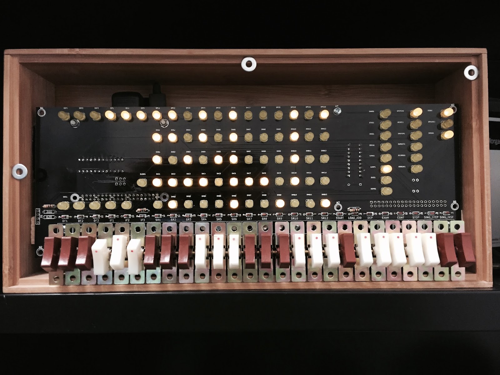
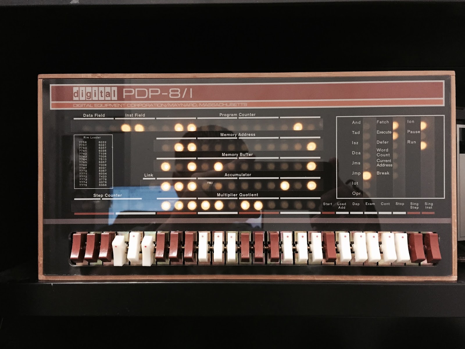
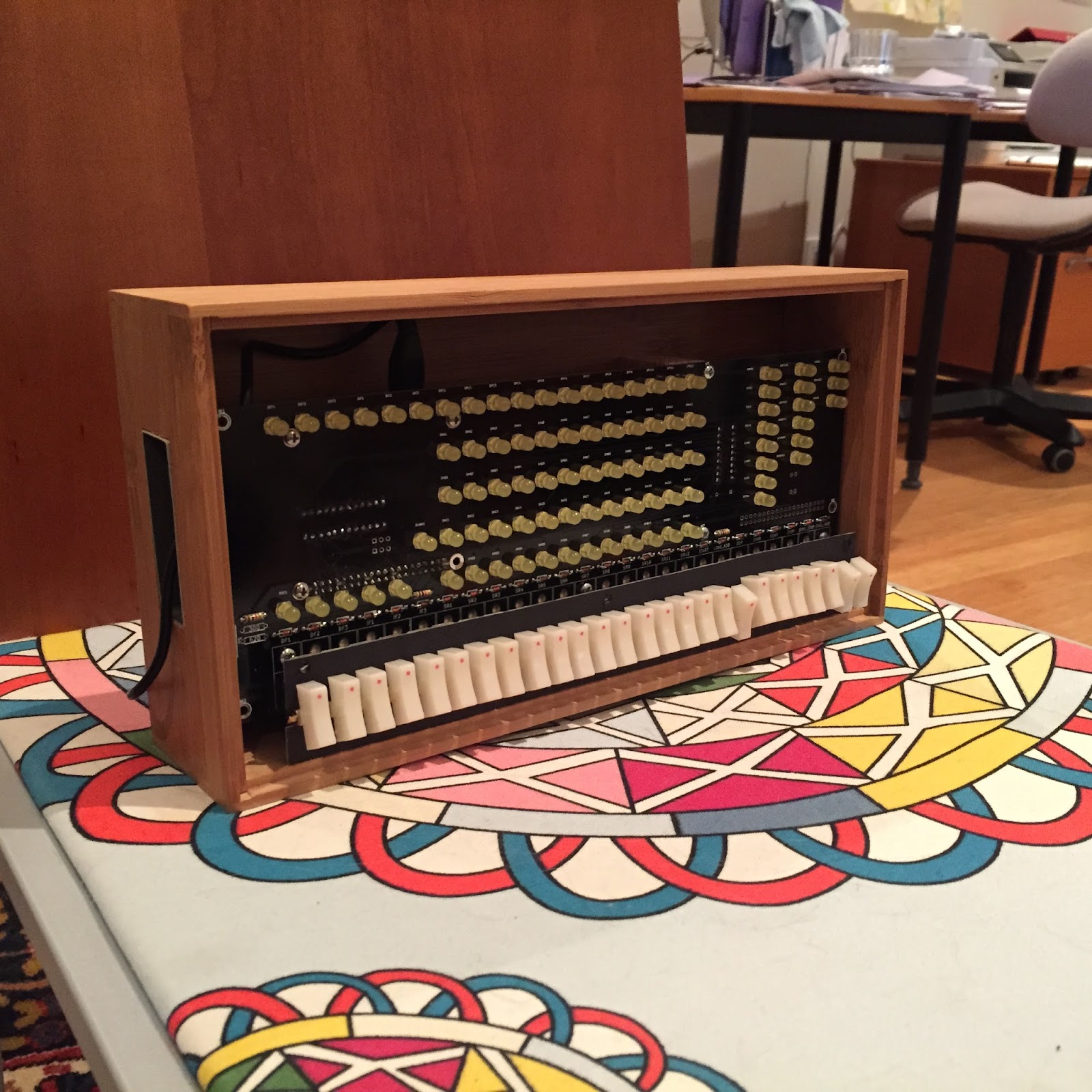
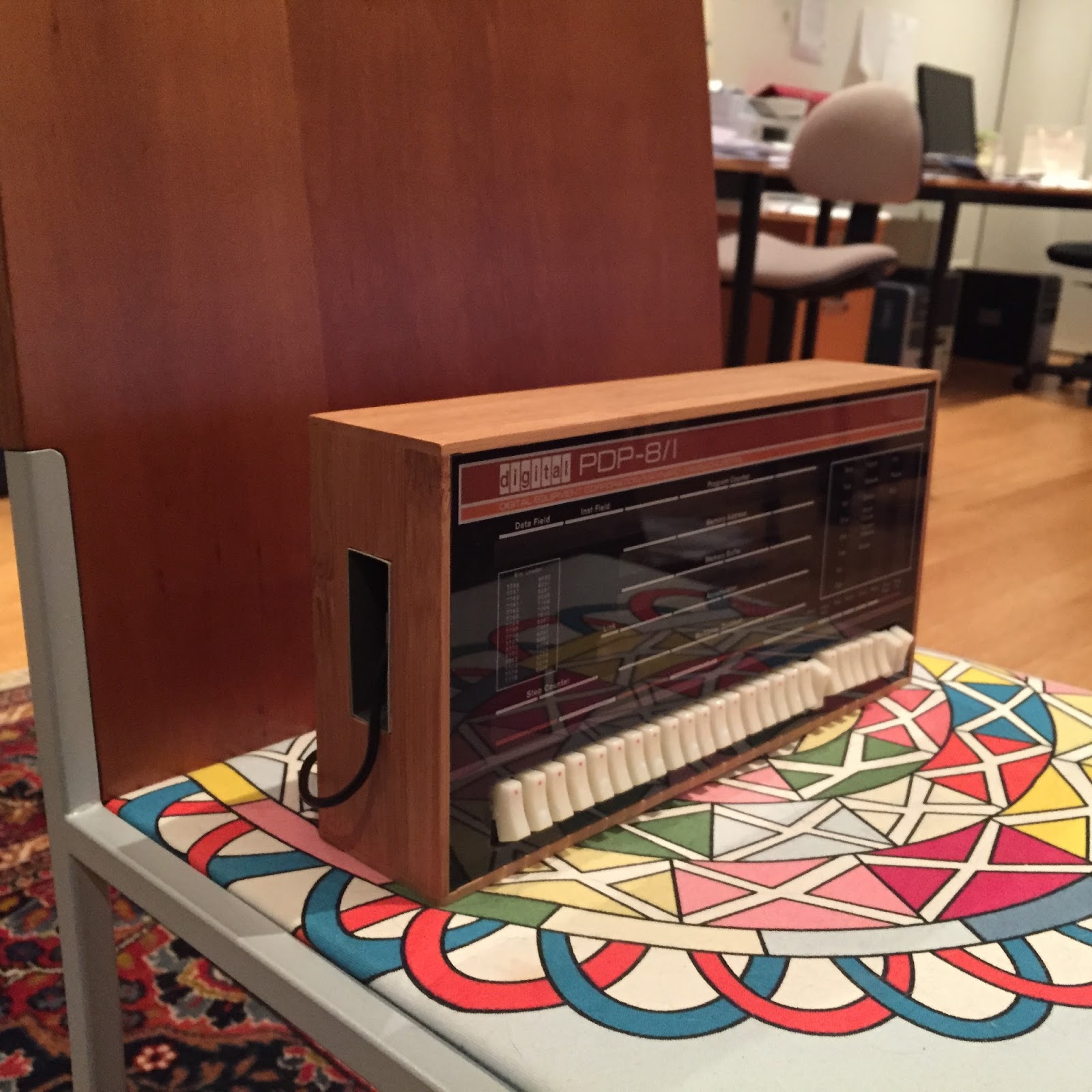
I thoroughly enjoyed building this kit; didn't encounter any problems. Oscar, thank you for your efforts in making this experience available to all! Some enthusiasts probably won't like my configuration but it works for me. I decided to have it lay down on the table to make operating the switches easier to accomplish. The reflection of my blunt fingertips revealed in the glass of the adjacent netbook as I took the picture give a clue as to why I wanted it this way. Two minutes with a file to form the slot for the ribbon cable. No need to make any other holes in the case. The pi is very accessible, I prefer this (can't leave the thing alone, always changing something). Front panel will eventually attach with velcro, if I ever get around to that. For now, friction and gravity serve to hold the panel in nicely. The pi has a case but you could easily miss this if you don't look closely. I had a pi 3 on hand already so it was put to work. Running a recent unmodified Raspbian, it boots to blinky lights on the pidp8 in about 10 seconds. I installed XRDP under Raspbian and use Windows Remote Desktop Client so that the netbook can serve as my terminal (again, the purists may be cringing). Pi and netbook are currently connect indirectly via wifi but a short cable could make that direct/wired.
I haven't done a whole lot with my new toy so far but everything seems to be working as expected.
I date back to the original PDP-8 era (my first computer experience was an IBM 1440 in 1965). Computer technology from that period is familiar to me but I completely missed the DEC family experience. I now have an opportunity to catch up! Again thank you Oscar, Bob Supnick, and all of the others.
Add me to the list of persons eagerly awaiting the PDP-11 version!
- ted agar
Warren Young
I decided to have it lay down on the table to make operating the switches easier to accomplish.
The reflection of my blunt fingertips revealed in the glass of the adjacent netbook as I took the picture give a clue as to why I wanted it this way.
Two minutes with a file to form the slot for the ribbon cable.
Front panel will eventually attach with velcro, if I ever get around to that. For now, friction and gravity serve to hold the panel in nicely.
I installed XRDP under Raspbian and use Windows Remote Desktop Client so that the netbook can serve as my terminal (again, the purists may be cringing)
Oscar Vermeulen
Front panel will eventually attach with velcro, if I ever get around to that. For now, friction and gravity serve to hold the panel in nicely.Mine is friction-fit as well. It's gotten a bit looser over time as the wood gives way to the harder plastic, but it's still in no danger of falling off.

jackva...@gmail.com
Ted Agar
I like your suggestion regarding the door stops. That would get the thing closer to an ideal position for me.
Oscar,
You gave me the perfect excuse to do nothing further to hold the panel in. If it becomes problematic (unlikely) I'll deploy the tape technique.
ted
Tom Stewart

Warren Young
1. I take it the board supports "real" RS232 voltage levels since you are using it with an actual terminal?
2. Do I have to populate the X and 2*X resistors for serial port access?
Where did you source the molex connector?
Did you have the proper molex crimp tool?
slob
1. I like using connectors but the expense for the proper tools/crimpers is crazy. I use Chinese Molex clones all the time,by soldering and "crimping" with a pair of needlenose. Never a problem and you can't see the bit of ugliness :)
2. On that subject: My IDC "vise" for ribbon cable is a Harbor Freight machinists' vise. You have to be careful but it works. I haven't screwed one up in a long time if you don't count making them backwards! True story: when I repaired computers in the late 70's and early 80's, I once disassembled a 50-pin IDC and put the connector on properly (our factory made it incorrectly) using a pair of pliers and my shoe as a mallet on a concrete floor. And, I had just spent 15 minutes explaining to the new owners of the computer how delicate the hard disk was. I was 150 miles away from the proper tools. The hard disk worked until the computer was decommissioned!
3. One of these days, I would like to lay out a 25-pin max-232 adapter like the 9-pin Chinese units. Every time I work with classic computers, I feel "wrong" using 9 pin connectors, even though most of the time we wind up using three wires.
4. I did break down and buy an MMJ crimper for my Pidp8 and the VT320's, They are getting harder to find and the connectors are getting tougher also at a reasonable price. I bought the cheapest one I could find on eBay and after a little filing, it worked.
5. I haven't seen a Greenlee DB-25 or DB-9 die set on eBay in a while. They were fairly cheap when they were available :( Those were wonderful for making a chassis or back panel. It is SO time consuming nibbling and filing those out.
Tom Stewart
On Saturday, April 8, 2017 at 11:00:21 PM UTC-4, slob wrote:
...
4. I did break down and buy an MMJ crimper for my Pidp8 and the VT320's, They are getting harder to find and the connectors are getting tougher also at a reasonable price. I bought the cheapest one I could find on eBay and after a little filing, it worked
AB
And finally, racked in all its glory


Warren Young
Here it is inside an unused aluminium box
- It looks like the HDMI screen is configured for about 60 columns? Is it just not capable of 80 column output, or is the font size just too small for your wishes?
- I take it this vertical output orientation is a well-known Raspberry Pi configuration, covered in the docs?
- I have never heard of a vintage "Ibex" computer brand. Google is of no help here. Care to help a vintage computer geek out here? :)
- The other beige gear looks like IBM stuff from the PS/2 era, but probably from higher up the line. Care to fill in the details?
AB
display_rotate=0 Normal
display_rotate=1 90 degrees
display_rotate=2 180 degrees
display_rotate=3 270 degrees
display_rotate=0x10000 horizontal flip
display_rotate=0x20000 vertical flip
I used display_rotate=1. Unfortunately my screen is a little big for the hole I cut (i am not a great metalworker) so I lost a few text rows along the way :-) Not sure exactly the number of columns I am getting (will check) or why... my hope for the screen is that it will be the "always on" console teletype. (Actually my real hope is for a *real* teletype 43 ... but that could be little way in the future!)
My Ibex is a CP/M machine using 8" drives. Made in Japan as I recall. It is a delightful but rather odd looking office-grade machine which I works quite well - but one of the 8" drives is a little unreliable. Internet photo:

I am going to get an HxC Floppy drive emulator and see if I can get it to work in the Ibex. The actual processor and memory etc. is in the keyboard, not inside the drive enclosure which I originally thought. I have a full collection of working office disks for the ibex which i want to archive so the disk images can be preserved (My Kaypro also pictured has an HxC drive which works great... yet again... i was dependent on lots of forum help!)
OK ....the other stuff pictured on the right are two AS/400 machines (models 9404 C10 and E10.) These beige fridge-sized boxes contain beautifully made, conservative IBM engineering goodness. I had very generous help from a bunch of guys on the AS400 google and midrange-L forums to get these up and running. I got both these machines for almost free on Craigslist but with no switchkeys or licenses or recovery tapes, etc. They were stuck in the AUTO position and even my local locksmith couldn't shift the key position to MANUAL. In the end I removed the jumpers and forced the position to MANUAL. Sadly though IBM have made it otherwise IMPOSSIBLE to "officially" restore or otherwise resurrect this glorious gear - they do not acknowledge the plight of honest hobbyists. You're not allowed to transfer ownership of these machines without buying full ($thousands) licenses. So they almost always end up scrapped which is a real shame because the hardware is pretty interesting.
I know almost nothing about IBMs, but I can tell you it was quite a thrill to get my 5250 block-based terminal firing into life when I finally got the machines to boot up (IPL) properly! The slightly more modern-looking server above the beige IBMs is the back of a newer IBM AS/400 9406 Model 270 which has some kind of hardware problem and won't properly IPL. This one has ethernet so I am quite excited to see if I can do some terminal emulation into it one day - - another project!
In my area almost nothing decent comes up on Craigslist... I do regularly scour the local hamfests as well... the ONE TIME some DEC gear came up, it was a working PDP11 with multiple drives, tons of hardware .. all for $700. That was the very week I *didnt* check craigslist :-)
In full disclosure my Altair is a clone.... and the tape drive at the bottom is a SCSI-connected IBM 9348-002. No idea how to get that to work.. yet another project!
cheers!
Andy
Leigh Klotz
Leigh/WA5ZNU
Tom Stewart
AB
Tom Stewart

Mike Markowski
http://udel.edu/~mm/pidp8i
After downloading the photos from my phone I realize I should have used a real camera. It has been great fun building the PiDP8. I spotted one at Vintage Computer Festival East last month and couldn't wait to build the kit. Now to read more of the PDP 8 manuals... The first computer I ever touched was as a 10th grader in 1978/79 - RSTS/E on a PDP 11/70. Fun days.
Mike
ab3ap
Tom Stewart
Mike Markowski
As to the 555 and 741, they are fun little things and really work! Microcenter also sells them if you have one nearby.
Mike
AB
Andy
On Monday, May 8, 2017 at 11:43:29 AM UTC-4, Mike Markowski wrote:
Mike Markowski
Mike
Mike Markowski

Cid

Obsolescence
On Saturday, May 13, 2017 at 1:24:54 AM UTC+2, Cid wrote:
I can wait to understand how it work! :) Is there somewhere I could find a simple program that I can input via the switches? I could via SSH, but just for the sake of trying :)
I will use it mainly as home router/firewall, but I'll surely play with the pdp side when I'll figure it out!
Cid

William Cattey


The connectors are currently friction fit, but I'll be epoxying in at least the power connector, because I've already moved it once.
I over-estimated my skill at cutting holes, and did a lower quality job than I would have liked.
slob
I used chassis mount USB females from China on my build, I suspect they are leftover from the desktop PC clone era.