BBC model B with beep of doom

discuss both original and modern hardware for the bbc micro/electron
Post Reply
User avatar
dwhweb
Posts: 15
Joined: Fri Jun 14, 2019 12:46 am
Contact:

BBC model B with beep of doom

Post by dwhweb »

Hey there,

I've been lurking around the forums for the past couple of days trying to bring myself up to speed with troubleshooting the BBC micro model B, and I'd appreciate any insight any of you might have.

Initially powered the machine on, and got a BASIC prompt - within 30 seconds the PSU let out lots of magic smoke, and searching informed me that this is pretty common. A couple of days later I received a replacement cap kit from the very helpful gentleman at IFEL, and spent ~4 hours fighting with the PSU casing, dropping screws and washers and swearing. The cap replacement itself took all of 5 minutes, once free. Powering on and checking the spade connectors with a multimeter and all voltages were correct, so far, so good.

I also discovered when opening the case that a Watford Electronics sideways rom expansion was installed, specifically this one -
Image

The horrible varta battery was intact but corrosion had crept into the 6502 socket, so I remove the CPU and cleaned both the CPU and socket with some contact cleaner and a brush - subsequently several of the contacts in the socket were so corroded they fell out. Annoying, but I should still be able to get the machine to boot, or so I thought.

I was aware that the RAM expansion was connected to several headers on the board so following the installation instructions at http://chrisacorns.computinghistory.org ... MBoard.pdf I restored the header for S21 so it now looks like this -
Image

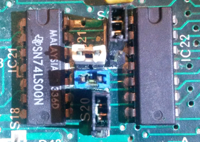
Could anyone verify this is definately correct?

I additionally reconnected the PSU to the applicable spades and powered on and recieved the long beep of doom and no video output.

I have subsequently tried the following troubleshooting steps with no improvement -

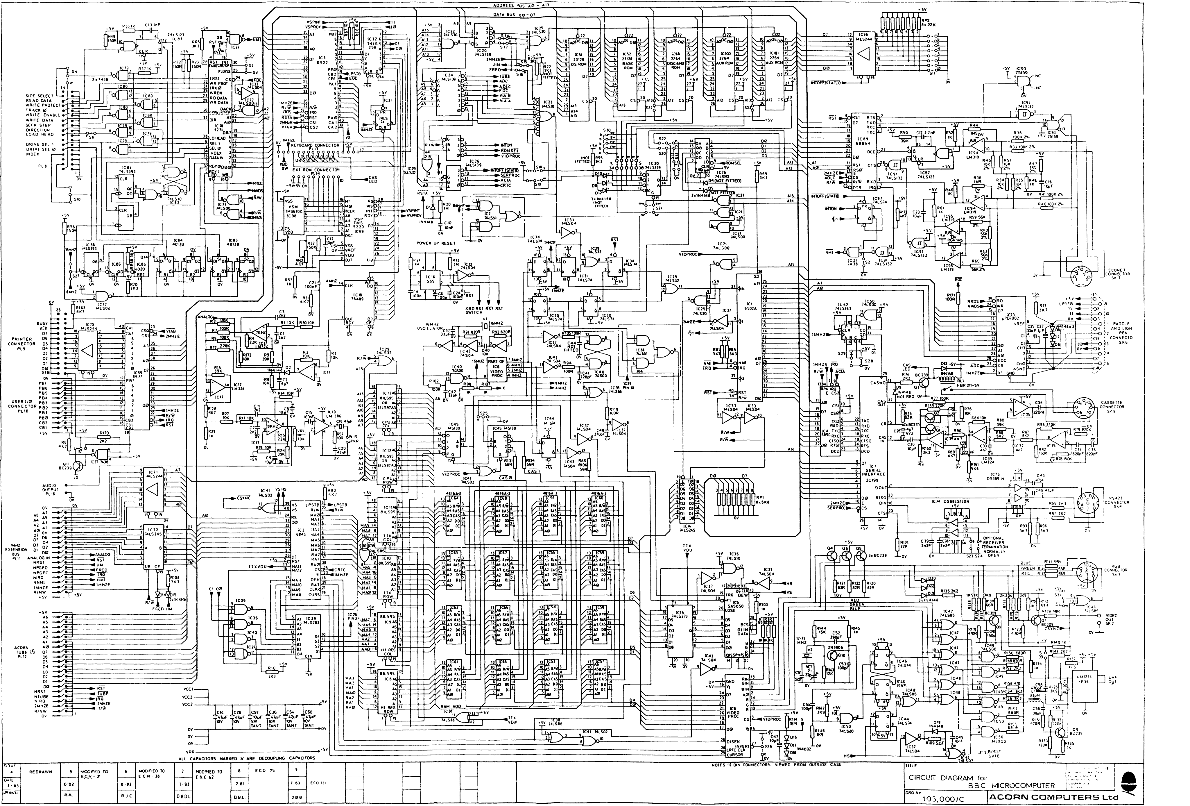
Following P18 of the troubleshooting guide at http://primrosebank.net/computers/bbc/d ... 0Micro.pdf I checked the 1Mhz bus and tube connectors for bent pins, removed all expansion ROMS in the bottom right of the board (apart from the OS ROM) and removed, cleaned and reseated the chips and sockets for IC1, IC2, IC3, IC7, IC51, IC69, IC73, IC78, IC81 and IC86. IC4 was also mentioned, but that chip is not socketed in my board - I could presumably remove it later but I didn't think it wise at that stage.

Removed IC7, IC73, IC69 and attempted to boot.

Swapped IC3 chip with IC69 chip and attempted to boot.

Tried the S25 jumper in both the south position and totally removed to check if the problem was RAM related - didn't help.

Checked back of the board for corrosion or damaged traces - looks in good condition.

Started following P39 of the service guide at http://wiki.itmuseum.in.ua/images/8/8b/ ... 5_Sec1.pdf, but I think I'm limited by the equipment I have (only a multimeter) - I found the following -
  • 6502 reset line is high but goes low when break key is pressed
  • IRQ line is permanently high which is apparently bad though I don't know what it means
  • Address bus lines are all around 3.5v, presumably bad?
  • The data bus lines vary between pins, presumably normal?
This is roughly the limit of my knowledge and I don't really know what I'm doing at this point, but as I understand I really need either a logic probe and/or an oscilliscope to really make sense of any output from the 6502 or any of the other ICs as the output varies too much for a multimeter to be of much use.

Both the guides I looked at seem to both advocate swapping various chips for known good ones around the point at which I left them, and I'd say the 6502 chip is suspect due to the formerly mentioned corrosion - it does look OK after I cleaned it however.

Any suggestions would be welcome. Should I be looking at buying a logic probe and/or an oscilliscope?
Last edited by dwhweb on Fri Jun 14, 2019 5:18 pm, edited 1 time in total.
User avatar
marcusjambler
Posts: 1147
Joined: Mon May 22, 2017 12:20 pm
Location: Bradford
Contact:

Re: BBC model B with beep of doom

Post by marcusjambler »

Hi Dwhweb

There are plenty people here to help you with this Beeb.
When you say there is corrosion on the 6502 socket... Is it the one on the WE card or the motherboard?

Its always best to remove any add-ons and work on getting the beeb running by itself first..

Also, it wont boot if the keyboard is disconnected... Its a little unclear... reading the above theres no mention of it.

Marcus
User avatar
dwhweb
Posts: 15
Joined: Fri Jun 14, 2019 12:46 am
Contact:

Re: BBC model B with beep of doom

Post by dwhweb »

Sorry, should have been clearer - the corrosion was in the 6502 socket on the WE card, not the BBC mainboard - when I removed the WE card I replaced the 6502 in the original mainboard socket, restored the S21 header and reconnected the black/red PSU spade connectors which as I understand should allow the machine to boot as stock.

I've been doing the various troubleshooting steps with the keyboard attached so that shouldn't be the culprit.
Kazzie
Posts: 1793
Joined: Sun Oct 15, 2017 8:10 pm
Location: North Wales
Contact:

Re: BBC model B with beep of doom

Post by Kazzie »

Hi,

S21 looks to be set up in the correct way. You can see a guide for a minimal boot configuration on the BeebWiki site, which will indicate which chips can be removed from the mainboard for testing purposes. Though the measurements you've taken with the multimeter lead me to suspect that the fault may not be with one of those chips.

(The pictures you posted are excellent, by the way: clear and nicely focused, so it's easy to see all the details.)

With regard to your multimeter measurements on the 6502:
  • The behaviour of the break line (pin 40) is good.
  • The IRQ pin is an active-low signal (typically written as /IRQ or similar). It should only go low when a device is requesting an interrupt of the CPU, so it's not inherently faulty for it to be constantly high.
  • The fact that the address bus' pins are all 3.5V indicates that the CPU is not busy fetching instructions. If it were, it would be changing the values on the address bus in order to fetch subsequent instructions from memory. The Model B's 6502 typically doesn't manage to drive the voltages of its address bus higher than 3.5V, so the voltage isn't an issue, it's the fact that they're all fixed at the same value.
(Assuming you're taking a DC voltage measurement with your multimeter, that will be giving a mean average voltage for each measurement. If you were getting readings in the 1-3V range, that could be an average of a number of low (0V) and high (~3.5V) values. The fact that they're all at the upper end of the 6502's range indicates that it's not giving any 0V outputs, they're all high.)

In order for a 6502 CPU to start running, it not only needs a reset signal on pin 40, but it needs a good clock input. (If it doesn't see a clock signal, it doesn't think it's time for it to do anything.) This clock signal is generated by the video chip (IC6), and is input to the 6502 on pin 37 (Phi 0). The 6502 generates another clock signal (Phi 1) based on this input, which is output to the rest of the board on pin 3. If there's no clock signal generated on pin 3, then that indicates that the input clock on pin 37 isn't present, or isn't good enough for the 6502 to recognise.

Measuring clock signals with only a multimeter can be a bit tricky, as few models are able to measure frequency. An oscilloscope is a better tool for this job, if you have one. There is, however, some benefit from measuring a clock's DC voltage with a multimeter, as for a good clock signal with a 50% duty cycle it should give an average of ~2.5V: half the time on (5V), half the time off (0V). A bad clock signal could also do this, so it's not a sure-fire conclusion.

:arrow: Could you measure the DC voltage at the following pins:
  • IC6, pins 8,7,6,5 and 4. These are the raw 16, 8, 4, 2 and 1MHz clock signals generated by the video processor
  • IC1, pins 37, 3, and 39. These are the Phi 0, Phi 1, and Phi 2 clocks on the CPU.
  • IC37 (a 74ls04), pins 11 and 10. This inverts the 2MHz Phi 0 signal before passing it on to the rest of the board.
If these all measure around 2.5V (with the possible exception of IC6 pin 8 ), that would suggest that your Beeb's clock signals are probably fine. If any are significantly different, that will show us where the fault may lie.
Last edited by Kazzie on Fri Jun 14, 2019 7:56 pm, edited 1 time in total.
BBC Model B 32K issue 7, Sidewise ROM board with 16K RAM
Archimedes 420/1 upgraded to 4MB RAM, ZIDEFS with 512MB CF card
RiscPC 600 under repair
Acorn System 1 home-made replica
User avatar
Elminster
Posts: 4315
Joined: Wed Jun 20, 2012 9:09 am
Location: Essex, UK
Contact:

Re: BBC model B with beep of doom

Post by Elminster »

dwhweb wrote: Fri Jun 14, 2019 5:16 pm
Any suggestions would be welcome. Should I be looking at buying a logic probe and/or an oscilloscope?
Definitely a logic probe first. It is 1/10 price of a scope. And easier and quicker to use. I have a scope but always start with the logic probe to narrow things down a bit. I think the last Beeb I fixed I only used the scope to check the clock speed, all the rest of the debugging I did with a probe.
User avatar
dwhweb
Posts: 15
Joined: Fri Jun 14, 2019 12:46 am
Contact:

Re: BBC model B with beep of doom

Post by dwhweb »

Thanks everyone for the excellent information.
Kazzie wrote: Fri Jun 14, 2019 7:46 pm :arrow: Could you measure the DC voltage at the following pins:
  • IC6, pins 8,7,6,5 and 4. These are the raw 16, 8, 4, 2 and 1MHz clock signals generated by the video processor
  • IC1, pins 37, 3, and 39. These are the Phi 0, Phi 1, and Phi 2 clocks on the CPU.
  • IC37 (a 74ls04), pins 11 and 10. This inverts the 2MHz Phi 0 signal before passing it on to the rest of the board.
If these all measure around 2.5V (with the possible exception of IC6 pin 8 ), that would suggest that your Beeb's clock signals are probably fine. If any are significantly different, that will show us where the fault may lie.
IC6 pins 8, 7, 6, 5 and 4 read 1.5v, 1.63v, 1.9v, 1.86v and 2v respectively
IC1 pins 37, 3 and 39 are all ~2v
IC37 pins 11 and 10 are 1.9v and 1.85v respectively

So these are all a bit of a mixed bag, does this suggest that IC6 is faulty as it isn't generating the correct clocks? The heatsink did come off rather easily when I was removing the WE board and the thermal paste underneath was pretty dry though I just put that down to age.
User avatar
1024MAK
Posts: 12780
Joined: Mon Apr 18, 2011 5:46 pm
Location: Looking forward to summer in Somerset, UK...
Contact:

Re: BBC model B with beep of doom

Post by 1024MAK »

The S20, S21 and S22 links (jumper shunts) in your photo appear to be correct.
Here is a photo showing the correct configuration for normal on board sideways ROMs, as in one of my machines (a BBC B issue 7 board, please ignore the violet and grey wires, they are for a modification):
Image

Mark
Attachments
S20, S21 and S22 links - normal configuration
User avatar
1024MAK
Posts: 12780
Joined: Mon Apr 18, 2011 5:46 pm
Location: Looking forward to summer in Somerset, UK...
Contact:

Re: BBC model B with beep of doom

Post by 1024MAK »

dwhweb wrote: Fri Jun 14, 2019 8:50 pm Thanks everyone for the excellent information.
Kazzie wrote: Fri Jun 14, 2019 7:46 pm :arrow: Could you measure the DC voltage at the following pins:
  • IC6, pins 8,7,6,5 and 4. These are the raw 16, 8, 4, 2 and 1MHz clock signals generated by the video processor
  • IC1, pins 37, 3, and 39. These are the Phi 0, Phi 1, and Phi 2 clocks on the CPU.
  • IC37 (a 74ls04), pins 11 and 10. This inverts the 2MHz Phi 0 signal before passing it on to the rest of the board.
If these all measure around 2.5V (with the possible exception of IC6 pin 8 ), that would suggest that your Beeb's clock signals are probably fine. If any are significantly different, that will show us where the fault may lie.
IC6 pins 8, 7, 6, 5 and 4 read 1.5v, 1.63v, 1.9v, 1.86v and 2v respectively
IC1 pins 37, 3 and 39 are all ~2v
IC37 pins 11 and 10 are 1.9v and 1.85v respectively

So these are all a bit of a mixed bag, does this suggest that IC6 is faulty as it isn't generating the correct clocks? The heatsink did come off rather easily when I was removing the WE board and the thermal paste underneath was pretty dry though I just put that down to age.
If using a normal multimeter (that is, not a really expensive model), these are the kind of results I would expect. ULA, TTL and NMOS chips are not able to take their output pins all the way up to +5V under load, plus as the frequency of the signal gets higher, a normal multimeter will tend to produce a lower indicated value.

The minimum voltage for a logic one / logic high is 2V.

Mark
User avatar
dwhweb
Posts: 15
Joined: Fri Jun 14, 2019 12:46 am
Contact:

Re: BBC model B with beep of doom

Post by dwhweb »

Thanks again for the replies.
1024MAK wrote: Sat Jun 15, 2019 11:58 am If using a normal multimeter (that is, not a really expensive model), these are the kind of results I would expect. ULA, TTL and NMOS chips are not able to take their output pins all the way up to +5V under load, plus as the frequency of the signal gets higher, a normal multimeter will tend to produce a lower indicated value.

The minimum voltage for a logic one / logic high is 2V.

Mark
Yeah, just a standard multimeter, nothing particularly fancy.

So if these do look to be OK, what is the most sensible way to proceed?
User avatar
1024MAK
Posts: 12780
Joined: Mon Apr 18, 2011 5:46 pm
Location: Looking forward to summer in Somerset, UK...
Contact:

Re: BBC model B with beep of doom

Post by 1024MAK »

dwhweb wrote: Sat Jun 15, 2019 1:08 pm So if these do look to be OK, what is the most sensible way to proceed?
As the machine worked briefly before you saw the smoke, I suspect there is not much wrong with it.

One problem with expansion boards, is the pins in the pin header connectors are larger in diameter compared to the legs of a DIL chip. Hence after a expansion board has been fitted, the contacts in the socket(s) on the main Beeb board where an expansion board has been, may not make proper contact with the pins of a chip when said chip is inserted in the socket.

So I suggest you check this out next. Where possible, using the schematic/ circuit diagram as a guide, continuity test each pin to another connection / chip pin elsewhere on the board.

Mark
User avatar
dwhweb
Posts: 15
Joined: Fri Jun 14, 2019 12:46 am
Contact:

Re: BBC model B with beep of doom

Post by dwhweb »

1024MAK wrote: Sat Jun 15, 2019 6:16 pm One problem with expansion boards, is the pins in the pin header connectors are larger in diameter compared to the legs of a DIL chip. Hence after a expansion board has been fitted, the contacts in the socket(s) on the main Beeb board where an expansion board has been, may not make proper contact with the pins of a chip when said chip is inserted in the socket.
I suspect this is at least part of the problem, I've been round the 6502 twice doing continuity tests and some pins make inconsistent contact after seating and reseating the chip - the only pin that seems to be consistently disconnected is pin 4 (IRQ). As I understand it, pin 39 (Phi 2) isn't connected to anything - is that correct? (forgive me if some of these questions seem stupid, this is all largely new to me).

I followed this schematic to work out where everything was connected, and the diagram on P19 of the Troubleshooting the BBC micro guide to work out where the chips are.

To save others the pain of having to squint at the schematic, I created the following table that others can use to check whether their 6502 socket is properly soldered in -
6502 pinConnection pointAddress lineData lineConnected?
3IC37 P11
4R85
6R81
9IC51 P10A0
10IC51 P9A1
11IC51 P8A2
12IC51 P7A3
13IC51 P6A4
14IC51 P5A5
15IC51 P4A6
16IC51 P3A7
17IC51 P25A8
18IC51 P24A9
19IC51 P21A10
20IC51 P23A11
22IC51 P2A12
23IC51 P26A13
24IC51 P27A14
25IC51 P1A15
26IC4 P15D7
27IC4 P16D6
28IC4 P17D5
29IC4 P18D4
30IC4 P19D3
31IC4 P20D2
32IC4 P21D1
33IC4 P22D0
34IC33 P13
37IC29 P11
38R69
39?
40Pad adjacent to pin on track
I have some DIP40 sockets and another 6502 on the way for good measure so I'll let you all know how I get on once I've put in a new socket.
Last edited by dwhweb on Sun Jun 16, 2019 1:56 pm, edited 1 time in total.
User avatar
dwhweb
Posts: 15
Joined: Fri Jun 14, 2019 12:46 am
Contact:

Re: BBC model B with beep of doom

Post by dwhweb »

One DIP socket replacement later -

Image

Thank you all so much for your help.

Next task is to attempt to replace the DIP socket on the WE sideways RAM expansion and see if that's salvagable, though it might be beyond repair - it looks pretty grotty and rotten from the corrosion. Assuming I can get it going, can I replace that varta battery with something more modern? I saw in one of the topics that someone used three rechargable AAAs in a holder, would that be suitable for my board?
User avatar
1024MAK
Posts: 12780
Joined: Mon Apr 18, 2011 5:46 pm
Location: Looking forward to summer in Somerset, UK...
Contact:

Re: BBC model B with beep of doom

Post by 1024MAK »

Well done =D> :D
dwhweb wrote: Fri Jun 21, 2019 11:12 pmNext task is to attempt to replace the DIP socket on the WE sideways RAM expansion and see if that's salvagable, though it might be beyond repair - it looks pretty grotty and rotten from the corrosion. Assuming I can get it going, can I replace that varta battery with something more modern? I saw in one of the topics that someone used three rechargable AAAs in a holder, would that be suitable for my board?
Clean the board using distilled (white) vinegar (search the forum for "vinegar").
Yes, three NiMH 1.2V AAA or AA size cells in a suitable battery will do. Get the low self discharge (long shelf life) type though (like Eneloop or similar), not the normal consumer grade. An ordinary NiMH type is not suitable.

Mark
User avatar
tricky
Posts: 7695
Joined: Tue Jun 21, 2011 9:25 am
Contact:

Re: BBC model B with beep of doom

Post by tricky »

Well done, and thanks for the table.
Post Reply

Return to “8-bit acorn hardware”