UPGRADING REPAIRING PCs
UPGRADING REPAIRING PCs
UPGRADING REPAIRING PCs

You also want an ePaper? Increase the reach of your titles
YUMPU automatically turns print PDFs into web optimized ePapers that Google loves.
<strong>UPGRADING</strong><br />
AND<br />
<strong>REPAIRING</strong> <strong>PCs</strong><br />
TECHNICIAN’S PORTABLE<br />
REFERENCE<br />
SECOND EDITION<br />
Scott Mueller and Mark Edward Soper
Upgrading and Repairing <strong>PCs</strong><br />
Technician’s Portable Reference,<br />
Second Edition<br />
Copyright© 2001 by Que<br />
All rights reserved. No part of this book shall be reproduced, stored<br />
in a retrieval system, or transmitted by any means, electronic,<br />
mechanical, photocopying, recording, or otherwise, without written<br />
permission from the publisher. No patent liability is assumed<br />
with respect to the use of the information contained herein.<br />
Although every precaution has been taken in the preparation of<br />
this book, the publisher and authors assume no responsibility for<br />
errors or omissions. Neither is any liability assumed for damages<br />
resulting from the use of the information contained herein.<br />
International Standard Book Number: 0-7897-2454-5<br />
Library of Congress Catalog Card Number: 00-104012<br />
Printed in the United States of America<br />
First Printing: October 2000<br />
02 01 00 4 3 2 1<br />
Trademarks<br />
All terms mentioned in this book that are known to be trademarks<br />
or service marks have been appropriately capitalized. Que cannot<br />
attest to the accuracy of this information. Use of a term in this<br />
book should not be regarded as affecting the validity of any trademark<br />
or service mark.<br />
Warning and Disclaimer<br />
Every effort has been made to make this book as complete and<br />
accurate as possible, but no warranty or fitness is implied. The<br />
information provided is on an as is basis. The authors and the publisher<br />
shall have neither liability nor responsibility to any person or<br />
entity with respect to any loss or damages arising from the information<br />
contained in this book.
Associate Publisher<br />
Greg Wiegand<br />
Senior Acquisitions Editor<br />
Jill Byus Schorr<br />
Senior Development Editor<br />
Rick Kughen<br />
Managing Editor<br />
Thomas F. Hayes<br />
Project Editor<br />
Karen S. Shields<br />
Copy Editor<br />
Megan Wade<br />
Technical Editor<br />
Mark Reddin<br />
Proofreader<br />
Jeanne Clark<br />
Indexer<br />
Mary SeRine<br />
Interior Design<br />
Kevin Spear<br />
Cover Design<br />
Karen Ruggles<br />
Layout Technicians<br />
Heather Hiatt Miller<br />
Stacey Richwine-DeRome<br />
iii
Contents at a Glance<br />
1 General Technical Reference 1<br />
2 System Components and Configuration 19<br />
3 BIOS Configurations and Upgrades 69<br />
4 SCSI and IDE Hard Drives and Optical Drives 93<br />
5 Floppy, Removable, Tape, and Flash Memory Storage 143<br />
6 Serial Ports and Modems 165<br />
7 Parallel Ports, Printers, Scanners, and Drives 189<br />
8 USB and IEEE-1394 Ports and Devices 205<br />
9 Keyboards, Mice, and Input Devices 215<br />
10 Video and Audio 237<br />
11 Networking 271<br />
12 Operating System Installation and Diagnostic Testing 299<br />
13 Tools and Techniques 309<br />
14 Connector Quick Reference 317<br />
Index 329
Contents<br />
1 General Technical Reference 1<br />
PC Subsystem Components Quick Reference 1<br />
The Motherboard and Its Components 2<br />
Understanding Bits, Nibbles, and Bytes 3<br />
Standard Capacity Abbreviations and Meanings 3<br />
Glossary of Essential Terms 5<br />
PC99 Color Standards 10<br />
Hexadecimal/ASCII Conversions 10<br />
2 System Components and Configuration 19<br />
Processors and Their Data Bus Widths 19<br />
Differences Between PC/XT and AT Systems 20<br />
Intel and Compatible Processor Specifications 21<br />
Troubleshooting Processor Problems 27<br />
Motherboard Form Factors 29<br />
Baby-AT Motherboard 30<br />
LPX Motherboard 31<br />
ATX Motherboard 31<br />
NLX Motherboard 32<br />
Which Motherboard Is Which? 32<br />
PC99 Color-Coding for Ports 33<br />
Power Supplies 34<br />
LPX Versus ATX Power Supplies 34<br />
Power Connectors for the Drive(s) 36<br />
Quick-Reference Chart for Troubleshooting Power<br />
Supplies 37<br />
Memory Types 38<br />
30-Pin SIMM 39<br />
72-Pin SIMM 39<br />
DIMMs 40<br />
RDRAM 40<br />
DDR SDRAM 41<br />
Parity Versus Non-Parity Memory 42<br />
Requirements for ECC Memory Use 43<br />
Using the Divide by 3 Rule to Determine Parity<br />
Support 43<br />
Using the Divide by 9 Rule to Determine Parity<br />
Support 43<br />
Expanding Memory on a System 44<br />
Memory Troubleshooting 45<br />
Memory Usage Within the System 46<br />
Hardware and Firmware Devices That Use Memory<br />
Addresses 46<br />
Using Memory Addresses Beyond 1MB (0FFFFF) 49<br />
Determining Memory Address Ranges in Use 49
vi<br />
Contents<br />
Other Add-On Card Configuration Issues 50<br />
IRQs 50<br />
DMA 52<br />
Determining Actual IRQ and DMA Usage 52<br />
I/O Port Addresses 54<br />
Determining Actual I/O Address Ranges in Use 57<br />
Troubleshooting Add-on Card Resource Conflicts 57<br />
Expansion Slots 62<br />
ISA 62<br />
EISA—A 32-bit Version of ISA 62<br />
VL-Bus—A Faster 32-Bit Version of ISA 62<br />
PCI 66<br />
AGP 66<br />
3 BIOS Configurations and Upgrades 69<br />
What the BIOS Is and What It Does 69<br />
When a BIOS Update Is Necessary 69<br />
Specific Tests to Determine Whether Your BIOS Needs<br />
an Update 70<br />
Fixing BIOS Limitations—BIOS Fixes and Alternatives<br />
70<br />
How BIOS Updates Are Performed 71<br />
Where BIOS Updates Come From 71<br />
Precautions to Take Before Updating a BIOS 72<br />
How to Recover from a Failed BIOS Update Procedure 73<br />
Plug-and-Play BIOS 74<br />
PnP BIOS Configuration Options 75<br />
When to Use the PnP BIOS Configuration Options 77<br />
Other BIOS Troubleshooting Tips 77<br />
Soft BIOS CPU Speed and Multiplier Settings 78<br />
Determining Which BIOS You Have 79<br />
Determining the Motherboard Manufacturer for BIOS<br />
Upgrades 79<br />
Identifying Motherboards with AMI BIOS 79<br />
Identifying Motherboards with Award BIOS 81<br />
Identifying Motherboards with Phoenix or Microid<br />
Research BIOS 82<br />
Accessing the BIOS Setup Programs 82<br />
How the BIOS Reports Errors 83<br />
BIOS Beep Codes and Their Purposes 83<br />
AMI BIOS Beep Codes 84<br />
Award BIOS Beep Codes 84<br />
Phoenix BIOS Beep Codes 85<br />
IBM BIOS Beep and Alphanumeric Error Codes 85<br />
Microid Research Beep Codes 86<br />
Reading BIOS Error Codes 88<br />
Onscreen Error Messages 88<br />
Interpreting Error Codes and Messages 88<br />
BIOS Configuration Worksheet 89<br />
4 SCSI and IDE Hard Drives and Optical Drives 93<br />
Understanding Hard Disk Terminology 93<br />
Heads, Sectors per Track, and Cylinders 93<br />
Hard Drive Heads 93<br />
Sectors per Track 93<br />
Cylinders 94
Contents vii<br />
IDE Hard Drive Identification 94<br />
Master and Slave Drives 95<br />
Breaking the 504MB (528-Million-Byte) Drive Barrier 97<br />
Using LBA Mode 98<br />
When LBA Mode Is Necessary—and When Not to Use<br />
It 98<br />
Problems with LBA Support in the BIOS 99<br />
Dangers of Altering Translation Settings 99<br />
Detecting Lack of LBA Mode Support in Your System<br />
100<br />
Using FDISK to Determine Compatibility Problems<br />
Between the Hard Disk and BIOS 101<br />
Getting LBA and Extended Int13h Support for Your<br />
System 102<br />
Determining Whether Your System Supports Extended<br />
Int13h 103<br />
Drive Capacity Issues in Microsoft Windows 95 and 98<br />
104<br />
Sources for BIOS Upgrades and Alternatives for Large IDE<br />
Hard Disk Support 105<br />
Standard and Alternative Jumper Settings 106<br />
Improving Hard Disk Speed 107<br />
Ultra DMA 108<br />
UDMA/66 and UDMA/100 Issues 108<br />
Bus-Mastering Chipsets for IDE 109<br />
Benefits of Manual Drive Typing 111<br />
Troubleshooting IDE Installation 112<br />
SCSI 113<br />
SCSI Types and Data Transfer Rates 113<br />
Single-Ended Versus Differential SCSI 114<br />
Low-Voltage Differential Devices 114<br />
Recognizing SCSI Interface Cables and Connectors 115<br />
8-Bit SCSI Centronics 50-Pin Connector 115<br />
SCSI-2 High-Density Connector 115<br />
SCSI-3 68-Pin P Cable 116<br />
RAID Array, Hot Swappable 80-Pin Connector 116<br />
SCSI Drive and Device Configuration 117<br />
SCSI Device ID 117<br />
SCSI Termination 119<br />
SCSI Configuration Troubleshooting 120<br />
Hard Disk Preparation 124<br />
Using FDISK 125<br />
Drive-Letter Size Limits 125<br />
Large Hard Disk Support 125<br />
Benefits of Hard Disk Partitioning 126<br />
FAT-32 Versus FAT-16 Cluster Sizes 127<br />
Converting FAT-16 Partition to FAT-32 128<br />
NTFS Considerations and Default Cluster Sizes 128<br />
How FDISK and the Operating System Create and Allocate<br />
Drive Letters 129<br />
Assigning Drive Letters with FDISK 130<br />
High-Level (DOS) Format 132<br />
Replacing an Existing Drive 133<br />
Drive Migration for MS-DOS Users 133<br />
Drive Migration for Windows 9x/Me Users 134<br />
XCOPY32 for Windows 9x Data Transfer 134
viii<br />
Contents<br />
Hard Disk Drive Troubleshooting and Repair 135<br />
Optical Drive Interface Types 137<br />
MS-DOS Command-Line Access to CD-ROM Drives for<br />
Reloading Windows 137<br />
Troubleshooting Optical Drives 138<br />
Failure Reading a CD 138<br />
Failure Reading CD-R and CD-RW Disks in a CD-ROM<br />
or DVD Drive 139<br />
IDE/ATAPI CD-ROM Drive Runs Slowly 139<br />
Trouble Using Bootable CDs 140<br />
5 Floppy, Removable, Tape, and Flash Memory<br />
Storage 143<br />
Floppy Drives 143<br />
Where Floppy Drives Fail—and Simple Fixes 144<br />
The Drive Cover 144<br />
The Stepper Motor 144<br />
Interface Circuit Boards 145<br />
Read/Write Heads 145<br />
Floppy Drive Hardware Resources 145<br />
Don’t Use a Floppy Drive While Running a Tape<br />
Backup 146<br />
Disk Drive Power and Data Connectors 146<br />
Floppy Drive Troubleshooting 148<br />
Common Floppy Drive Error Messages—Causes and<br />
Solutions 149<br />
Removable Storage Drives 150<br />
Sources for “Orphan” Drive Media, Repairs, Drivers,<br />
and Support 153<br />
Emergency Access to Iomega Zip Drive Files in Case of<br />
Disaster 153<br />
Troubleshooting Removable Media Drives 154<br />
Types of Flash Memory Devices 155<br />
Tape Backup Drives and Media 155<br />
Common Tape Backup Standards 155<br />
Travan Tape Drives and Media 156<br />
Proprietary Versions of Travan Technology 157<br />
Getting Extra Capacity with Verbatim QIC-EX Tape<br />
Media 157<br />
OnStream ADR Tape Drives and Media 158<br />
Choosing the Best High-Performance Backup<br />
Technology 159<br />
Successful Tape Backup and Restore Procedures 160<br />
Tape Drive Troubleshooting 161<br />
Tape Retensioning 164<br />
6 Serial Ports and Modems 165<br />
Understanding Serial Ports 165<br />
Pinouts for Serial Ports 166<br />
Current Loop Serial Devices and 25-Pin Serial Ports<br />
168<br />
UARTs 169<br />
UART Types 169<br />
Identifying Your System UART 170<br />
High-Speed Serial Ports (ESP and Super ESP) 171<br />
Upgrading the UART Chip 171
Serial Port Configuration 172<br />
Avoiding Conflicts with Serial Ports 173<br />
Troubleshooting I/O Ports in Windows 9x and Me 173<br />
Advanced Diagnostics Using Loopback Testing 174<br />
Loopback Plug Pinouts—Serial Ports 175<br />
Modems 176<br />
Modems and Serial Ports 176<br />
Modem Modulation Standards 176<br />
56Kbps Standards 177<br />
Upgrading from x2 or K56flex to V.90 with Flash<br />
Upgrades 178<br />
External Versus Internal Modems 180<br />
Modem Troubleshooting 180<br />
Pinouts for External Modem Cable (9-Pin at PC) 184<br />
Win98SE, Windows 2000, Windows Me, and ICS 184<br />
Requirements for ICS 185<br />
Overview of the Configuration Process 185<br />
7 Parallel Ports, Printers, Scanners, and Drives 189<br />
Parallel Port Connectors 189<br />
Parallel Port Performance 190<br />
Parallel Port Configurations 191<br />
Testing Parallel Ports 191<br />
Troubleshooting Parallel Ports 192<br />
Printers 193<br />
Hewlett-Packard PCL Versions 194<br />
Comparing Host-Based to PDL-Based Printers 195<br />
Printer Hardware Problems 196<br />
Printer Connection Problems 199<br />
Printer Driver and Application Problems 201<br />
Troubleshooting Parallel Port and Other Types of Scanners 202<br />
Parallel Port Drives 203<br />
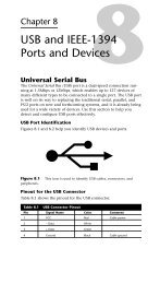
8 USB and IEEE-1394 Ports and Devices 205<br />
Universal Serial Bus 205<br />
USB Port Identification 205<br />
Pinout for the USB Connector 205<br />
Typical USB Port Locations 206<br />
Adding USB Ports to Your Computer 206<br />
Prerequisites for Using USB Ports and Peripherals 207<br />
Troubleshooting USB Ports 207<br />
Using USB Hubs with Legacy (Serial, Parallel, and PS/2)<br />
Ports 209<br />
Online Sources for Additional USB Support 209<br />
USB 2.0 209<br />
IEEE-1394 210<br />
Adding IEEE-1394 Ports to Your Computer 210<br />
Comparing USB and IEEE-1394 211<br />
Troubleshooting IEEE-1394 Host Adapters and Devices<br />
212<br />
IEEE-1394 and Linux 213<br />
Online Sources for Additional IEEE-1394 Support 213<br />
9 Keyboards, Mice, and Input Devices 215<br />
Keyboard Designs 215<br />
The 101-Key Enhanced Keyboard 215<br />
101-Key Versus 102-Key Keyboards 215<br />
The 104-Key Windows Keyboard 215<br />
Contents ix
x<br />
Contents<br />
Using Windows Keys 215<br />
Keyboard-Only Commands for Windows<br />
9x/NT4/2000/Me with Any Keyboard 216<br />
Standard Versus Portable Keyboards 219<br />
Keyswitch Types 219<br />
Cleaning a Foam-Element Keyswitch 220<br />
Adjusting Keyboard Parameters in Windows 221<br />
Keyboard Layouts and Scan Codes 221<br />
Keyboard Connectors 225<br />
Keyboard Connector Signals 226<br />
USB Keyboard Requirements 227<br />
Keyboard Troubleshooting and Repair 227<br />
Keyboard Connector Voltage and Signal Specifications 229<br />
Keyboard Error Codes 229<br />
Mice and Pointing Devices 230<br />
Mouse Motion Detection Methods 230<br />
Pointing Device Interface Types 230<br />
Wireless Mouse Types 231<br />
Software Drivers for the Mouse 231<br />
Alternative Pointing Devices 232<br />
Mouse Troubleshooting 233<br />
10 Video and Audio 237<br />
Selecting a Monitor Size 237<br />
Monitor Resolution 238<br />
CRTs Versus LCDs 238<br />
Common Monitor Resolutions 238<br />
LCD Versus CRT Display Size 239<br />
Monitor Power Management Modes 239<br />
VGA Video Connector Pinouts 241<br />
VGA DB-15 Analog Connector Pinout 241<br />
Digital Flat Panel Pinouts 242<br />
Digital Visual Interface Pinouts 243<br />
VGA Video Display Modes 244<br />
Video RAM 246<br />
Memory, Resolution, and Color Depth 247<br />
Determining the Amount of RAM on Your Display Card 249<br />
Local-Bus Video Standards 249<br />
RAMDAC 251<br />
Refresh Rates 252<br />
Adjusting the Refresh Rate of the Video Card 252<br />
Comparing Video Cards with the Same Chipset 253<br />
Setting Up Multiple Monitor Support in Windows<br />
98/Me/2000 253<br />
System Configuration Issues for Multiple-Monitor<br />
Support 256<br />
Video Card and Chipset Makers Model Reference 256<br />
3-D Chipsets 256<br />
Multimedia Devices 256<br />
Troubleshooting Video Capture Devices 257<br />
Testing a Monitor with Common Applications 258<br />
Audio I/O Connectors 260<br />
Connectors for Advanced Features 262
Contents xi<br />
Sound Quality Standards 263<br />
Configuring Sound Cards 263<br />
PCI Versus ISA Sound Cards 264<br />
Multifunction (Modem and Sound) Cards 264<br />
Troubleshooting Audio Hardware 265<br />
Hardware (Resource) Conflicts 265<br />
Detecting Resource Conflicts 265<br />
Most Common Causes of Hardware Conflicts with<br />
Sound Card 266<br />
Freeing Up IRQ 5 for Sound Card Use While Still<br />
Printing 267<br />
Other Sound Card Problems 267<br />
11 Networking 271<br />
Client/Server Versus Peer-to-Peer Networking 271<br />
Choosing Network Hardware and Software 272<br />
NIC 272<br />
UTP Cable 273<br />
Hub 273<br />
Software 273<br />
Network Protocols 275<br />
IP and TCP/IP 275<br />
Selecting a Network Data-Link Protocol (Specification) 276<br />
Network Cable Connectors 277<br />
Wire Pairing for Twisted-Pair Cabling 278<br />
Making Your Own UTP Cables 278<br />
Network Cabling Distance Limitations 280<br />
Cabling Standards for Fast Ethernet 281<br />
Specialized Network Options 281<br />
What About Home Networking? 281<br />
Wireless Networking Standards 282<br />
Wireless Network Configuration and Selection Issues<br />
284<br />
TCP/IP Network Protocol Settings 284<br />
TCP/IP Protocol Worksheet 285<br />
Troubleshooting Networks 287<br />
Troubleshooting Network Software Setup 287<br />
Troubleshooting Networks in Use 288<br />
Troubleshooting TCP/IP 289<br />
Direct Cable Connections 290<br />
Null Modem and Parallel Data-Transfer Cables 290<br />
Direct Connect Software 291<br />
Troubleshooting Direct Cable Connections 295<br />
12 Operating System Installation and Diagnostic<br />
Testing 299<br />
Installing an Operating System on an Empty Drive 299<br />
Installing MS-DOS 299<br />
Installing Windows 9x 300<br />
Installing Windows Me 300<br />
Installing Windows NT 4.0 or Windows 2000 301<br />
Upgrading an Operating System 302<br />
Installing to the Same Folder 302<br />
Installing to a Different Folder 302<br />
Installing to a Different Partition 302
xii<br />
Contents<br />
Checking for IRQ, DMA, I/O, and Memory Usage 302<br />
MS-DOS Using MSD 302<br />
Windows 9x/2000/Me 303<br />
Windows NT 4.0 304<br />
Software Toolkit 304<br />
13 Tools and Techniques 309<br />
General Information 309<br />
Hardware Tools and Their Uses 309<br />
Tools of the Trade—Drive Installation 310<br />
Tools of the Trade—Motherboard and Expansion Card<br />
Installation 311<br />
Tools of the Trade—External Device and Networking<br />
Installation 312<br />
Tools of the Trade—Data Transfer 313<br />
Tools of the Trade—Cleaning and Maintenance 314<br />
14 Connector Quick Reference 317<br />
Serial Ports and Cables 317<br />
Parallel Ports 318<br />
SCSI Ports 318<br />
USB and IEEE-1394 (FireWire) 319<br />
Video Connectors 321<br />
Video Ports 321<br />
Video Cables 322<br />
Sound Card Ports 323<br />
Sound Card External Ports 323<br />
Sound Card Internal Connectors 325<br />
Network and Modem Ports and Cables 325<br />
RJ-45 Port and Cable 325<br />
RJ-11 Port and Cable Connector 326<br />
Older Network Connectors 326<br />
Index 329
About the Authors<br />
Scott Mueller is president of Mueller Technical Research, an international<br />
research and corporate training firm. Since 1982, MTR has<br />
specialized in the industry’s longest running, most in-depth, accurate,<br />
and effective corporate PC hardware and technical training<br />
seminars, maintaining a client list that includes Fortune 500 companies,<br />
the U.S. and foreign governments, and major software and<br />
hardware corporations, as well as PC enthusiasts and entrepreneurs.<br />
His seminars have been presented to thousands of PC support professionals<br />
throughout the world.<br />
Scott Mueller has developed and presented training courses in all<br />
areas of PC hardware and software. He is an expert in PC hardware,<br />
operating systems, and data-recovery techniques. For more information<br />
about a custom PC hardware or data-recovery training seminar<br />
for your organization, contact Lynn at<br />
Mueller Technical Research<br />
21 Spring Lane<br />
Barrington Hills, IL 60010-9009<br />
Phone: (847) 854-6794<br />
Fax: (847) 854-6795<br />
Internet: scottmueller@compuserve.com<br />
Web: http://www.m-tr.com<br />
Scott has many popular books, articles, and course materials to his<br />
credit, including Upgrading and Repairing <strong>PCs</strong>, which has sold more<br />
than 2 million copies, making it by far the most popular PC hardware<br />
book on the market today.<br />
If you have questions about PC hardware, suggestions for the next<br />
edition of the book, or any comments in general, send them to<br />
Scott via email at scottmueller@compuserve.com.<br />
When he is not working on PC-related books or teaching seminars,<br />
Scott can usually be found in the garage working on performance<br />
projects. This year a Harley Road King with a Twin-Cam 95ci Stage<br />
III engine continues as the main project (it’s amazing how something<br />
with only two wheels can consume so much time and money<br />
), along with a modified 5.7L ‘94 Impala SS and a 5.9L Grand<br />
Cherokee (hotrod SUV).
Mark Edward Soper is president of Select Systems and Associates,<br />
Inc., a technical writing and training organization that has been in<br />
business since 1989. Select Systems specializes in revealing the hidden<br />
power and features in <strong>PCs</strong>, their hardware, and their software.<br />
Select Systems has developed training courses and manuals for computer<br />
training firms and industrial, manufacturing, and media<br />
clients in print, HTML, and Adobe Acrobat formats.<br />
Mark has taught computer troubleshooting and other technical<br />
subjects to thousands of students from Maine to Hawaii since 1992.<br />
He is an A+ Certified hardware technician and a Microsoft Certified<br />
Professional. He has been writing technical documents since the<br />
mid-1980s, and has contributed to several other Que books, including<br />
Upgrading and Repairing <strong>PCs</strong>, 11th and 12th Editions; Upgrading<br />
and Repairing Networks, 2nd Edition; and Special Edition Using<br />
Windows Millennium Edition. Mark co-authored the original edition<br />
of this book, and his first books on A+ Certification will be published<br />
after the revised A+ Certification Exams are released at the<br />
end of 2000. Watch for details about these and other book projects<br />
at the newly improved Que Web site at www.mcp.com.<br />
For more information about customized technical reference and<br />
training materials, contact<br />
Select Systems and Associates, Inc.<br />
1100 W. Lloyd Expy #104<br />
Evansville, IN 47708<br />
Phone: (812) 421-1170<br />
Fax: (812) 426-6138<br />
Email: mesoper@selectsystems.com<br />
Web: http://www.selectsystems.com<br />
Mark has been writing for major computer magazines since<br />
1990, with more than 125 articles in publications such as<br />
SmartComputing, PCNovice, PCNovice Guides, and the PCNovice<br />
Learning Series. His early work was published in WordPerfect<br />
Magazine, The WordPerfectionist, and PCToday. Many of Mark’s articles<br />
are available in back issue or electronically via the World Wide<br />
Web at www.smartcomputing.com. Select Systems maintains a subject<br />
index of all Mark’s articles at http://www.selectsystems.com.<br />
When he’s not sweating out a writing deadline, Mark enjoys life<br />
with his wife, Cheryl, a children’s librarian who is also a published<br />
writer. Their children (now 21, 20, 20, and 18) are all computer<br />
users, keeping him busy with their questions, and he also provides<br />
computer support to his local church. Mark still finds time to
watch, photograph, and (occasionally) ride trains. He’s using his<br />
years of experience with photography and computers to build a<br />
personal image archive, and he has also created archiving programs<br />
for a local university.<br />
Mark welcomes your comments and suggestions about this book.<br />
Send them to mesoper@selectsystems.com.<br />
About the Technical<br />
Editor<br />
Mark Reddin, MCSE, A+, is a Microsoft Certified Systems<br />
Engineer and an A+ Certified PC technician. In addition to his<br />
work as a Que technical editor, Mark provides consulting services<br />
for NT systems and business networks. He has enjoyed using computers<br />
at the hobbyist level since the days of the Atari 400. This<br />
interest led to a professional level of involvement and, after dabbling<br />
in programming, he discovered networking. He achieved his<br />
first certification from Microsoft in early 1998 and has worked as a<br />
configuration technician for a computer reseller as well as an NT<br />
specialist and general networking contractor.
Acknowledgments<br />
Mark would like to thank the following people: Scott Mueller,<br />
whose Upgrading and Repairing <strong>PCs</strong> has been on his “short list” of<br />
great computer books for more than 10 years and whose latest edition<br />
provided much of the material for this book; Jill Byus Schorr<br />
and Rick Kughen at Que, whose encouragement and guidance have<br />
helped make this book a success; Cheryl, who never stopped believing<br />
that I could write; and God, who gives all of us talents and abilities<br />
and cheers us on as we develop them.
Tell Us What You Think!<br />
As the reader of this book, you are our most important critic and<br />
commentator. We value your opinion and want to know what we’re<br />
doing right, what we could do better, what areas you’d like to see us<br />
publish in, and any other words of wisdom you’re willing to pass<br />
our way.<br />
As the associate publisher for this book, I welcome your comments.<br />
You can fax, email, or write me directly to let me know what you<br />
did or didn’t like about this book—as well as what we can do to<br />
make our books stronger.<br />
When you write, please be sure to include this book’s title and<br />
authors as well as your name and phone or fax number. I will carefully<br />
review your comments and share them with the authors and<br />
editors who worked on the book.<br />
Fax: 317-581-4666<br />
Email: hardware@mcp.com<br />
Mail: Macmillan USA<br />
201 West 103rd Street<br />
Indianapolis, IN 46290
Introduction<br />
If you’re a computer repair technician or student, you know<br />
just how crucial it is to have concise, yet detailed, technical specifications<br />
at your fingertips. It can mean the success or failure of<br />
your job.<br />
Unfortunately, most detailed hardware books are far too large to<br />
tote around in a briefcase, book bag, or in your back pocket—where<br />
you need them.<br />
Upgrading and Repairing <strong>PCs</strong>: Technician’s Portable Reference is the<br />
exception. This concise book provides just the information you<br />
need to upgrade or repair your PC, without weighing you down.<br />
Although you should consider this book to be a companion to<br />
Scott Mueller’s best-selling opus, Upgrading and Repairing <strong>PCs</strong>, you’ll<br />
also find that it stands quite well on its own. While much of the<br />
information is in the mother book, much of what is found here is<br />
presented in a boiled-down, easy-to-digest reference that will help<br />
you get the job done quickly and efficiently. You’ll also find that<br />
this portable reference contains some information not found in the<br />
main book—information that is specially geared to help the technician<br />
in the field.<br />
I recommend that you keep Upgrading and Repairing <strong>PCs</strong>, 12th<br />
Edition (ISBN 0-7897-2303-4) on your desk or workbench and<br />
Upgrading and Repairing <strong>PCs</strong>: Technician’s Portable Reference with your<br />
toolkit, so it’s ready to go with you anytime—whether it’s to a customer<br />
job site or a class.
Chapter 1<br />
General Technical<br />
Reference<br />
1<br />
PC Subsystem Components Quick<br />
Reference<br />
The following table lists the major PC subsystems and how they are<br />
configured. Use this table as a shortcut to the most likely place(s)<br />
to look for problems with these subsystems. Then, go to the appropriate<br />
chapter for more information.<br />
Table 1.1 Major PC Subsystems and Where to Configure Them<br />
How Configured and See Chapters<br />
Subsystem Components Controlled for Details<br />
Motherboard CPU, RAM, ROM, Jumper blocks (CPU) 2, 3<br />
expansion slots, BIOS (all others plus<br />
BIOS CPU on some systems)<br />
I/O ports Serial BIOS and operating<br />
system<br />
3, 6<br />
Parallel BIOS and operating<br />
system<br />
3, 7<br />
USB BIOS and operating<br />
system drivers<br />
3, 8<br />
PS/2 mouse MB jumper blocks<br />
or BIOS<br />
3, 9<br />
Keyboard BIOS 3, 9<br />
I/O devices Modem Driver software 6<br />
Sound card Driver software 10<br />
Input devices Keyboard, mouse, BIOS 9<br />
trackball, touchpad Driver software 9<br />
Scanner Driver software 7<br />
Standard<br />
mass storage<br />
Floppy BIOS 5<br />
IDE BIOS and jumper blocks 4<br />
Add-on CD-ROM, Zip, Jumper blocks and 4<br />
mass storage LS-120, other<br />
removable media<br />
driver software<br />
SCSI Jumper blocks and<br />
add-on BIOS card or<br />
driver software<br />
4
2<br />
Table 1.1 Major PC Subsystems and Where to Configure Them<br />
Contiuned<br />
Chapter 1—General Technical Reference<br />
How Configured and See Chapters<br />
Subsystem Components Controlled for Details<br />
Tape backup Jumper blocks and<br />
tape backup<br />
software<br />
4, 5<br />
Display Video card BIOS (basic features), 10<br />
and monitor operating system<br />
(advanced features)<br />
Power supply (same) Autoselected voltage<br />
or slider switch on<br />
unit; on/off switch<br />
2<br />
The Motherboard and Its<br />
Components<br />
Figure 1.1 shows a typical motherboard with its major components<br />
labeled as it would appear before installation in a system.<br />
Figure 1.1 A typical ATX motherboard (overhead view).<br />
Figure 1.2 shows the ports on a typical ATX motherboard as they<br />
would be seen from the rear of the system.
Understanding Bits, Nibbles, and Bytes 3<br />
Figure 1.2 Ports on the rear of a typical ATX motherboard.<br />
Understanding Bits, Nibbles, and<br />
Bytes<br />
The foundation of all memory and disk size calculations is the byte.<br />
When storing plain-text data, a byte equals one character.<br />
Data can also be stored or transmitted in portions of a byte. A bit<br />
equals 1/8 of a byte, or, in other words, a byte equals eight bits. A<br />
nibble equals 1/2 of a byte, or four bits. Thus, two nibbles equal one<br />
byte. Keep the difference between bits and bytes in mind as you<br />
review the table of standard capacity abbreviations and meanings.<br />
Standard Capacity Abbreviations and Meanings<br />
Use the following table to translate megabytes, gigabytes, and the<br />
other abbreviations used to refer to memory and disk space into<br />
their decimal or binary values.<br />
Unfortunately, some parts of the computer industry use the decimal<br />
values, while others use the binary values. Typically, hard disk<br />
and other drive manufacturers rate their products in decimal<br />
megabytes or gigabytes. On the other hand, the ROM BIOS on<br />
most (but not all) systems and the MS-DOS and Windows FDISK<br />
programs use binary megabytes or gigabytes, thus creating an<br />
apparent discrepancy in disk capacity. RAM is virtually always calculated<br />
using binary values.
Table 1.2 Standard Abbreviations and Meanings<br />
Decimal<br />
Abbreviation Description Power Dec<br />
Kbit or Kb Kilobit 103 1,00<br />
K or KB Kilobyte 103 1,00<br />
Mbit or Mb Megabit 106 1,00<br />
M or MB Megabyte 106 1,00<br />
Gbit or Gb Gigabit 109 1,00<br />
G or GB Gigabyte 109 1,00<br />
Tbit or Tb Terabit 1012 1,00<br />
T or TB Terabyte 1012 1,00
Note<br />
Glossary of Essential Terms 5<br />
For other conversion and reference tables, see the Technical<br />
Reference (found on the CD-ROM) of Upgrading and Repairing<br />
<strong>PCs</strong>, Twelfth Edition.<br />
Glossary of Essential Terms<br />
Table 1.3 Terms and Their Definitions<br />
Term Definition<br />
ACPI Advanced configuration and power interface; power management for<br />
all types of computer devices.<br />
AGP Accelerated graphics port; a fast dedicated slot interface between the<br />
video adapter or chipset and the motherboard chipset North Bridge;<br />
developed by Intel. AGP is 32 bits wide; runs at 66MHz; and can transfer<br />
1, 2, or 4 bits per cycle (1x, 2x, and 4x modes).<br />
APM Advanced power management; power management for hard drives<br />
and monitors.<br />
ATAPI AT attachment-packet interface; modified version of IDE that supports<br />
removable media and optical drives that use software drivers. Can<br />
coexist on the same cable with IDE hard drives.<br />
Beep code A series of one or more beeps used by the system BIOS to report<br />
errors. Beep codes vary by BIOS brand and version.<br />
BIOS Basic input/output system; a chip on the system board that controls<br />
essential devices, such as the keyboard, basic video display, floppy and<br />
hard drives, and memory.<br />
Cluster Also called allocation unit; the minimum disk space actually used by a<br />
file when it is stored; this size increases with larger drives due to the<br />
limitations of the FAT size.<br />
Color depth How many colors a video card can display at a given resolution; the<br />
higher the resolution, the more RAM required to display a given color<br />
depth.<br />
COM Communication port; also called serial port.<br />
Combo slot Also called shared slot; a pair of slots that share a single card bracket;<br />
only one of the two slots can be used at a time.<br />
Compact flash A type of flash memory device.<br />
CPU Central processing unit; the “brains” of a computer.<br />
CRT Cathode-ray tube; conventional TV-like picture tube display technology<br />
used on most desktop monitors.<br />
Data bus The connection that transmits data between the processor and the rest<br />
of the system. The width of the data bus defines the number of data<br />
bits that can be moved in to or out of the processor in one cycle.<br />
DCC Direct cable connection; Windows 9x/Me/2000 program that enables<br />
computers to link up through parallel or serial ports; Windows NT 4.0<br />
supports serial port linkups only.
6<br />
Chapter 1—General Technical Reference<br />
Table 1.3 Terms and Their Definitions Continued<br />
Term Definition<br />
Device Manager Tab in the System Properties sheet for Windows 9x/2000/Me that<br />
enables you to view, change the configuration of, and remove system<br />
and add-on devices.<br />
DFP Digital flat panel; an early digital monitor standard replaced by DVI.<br />
DIMM Dual inline memory module; leading type of memory device from late<br />
1990s to present; current versions have 168 edge connectors.<br />
DMA Direct memory access; data transfer method used by some devices to<br />
bypass the CPU and go directly to and from memory; some ISA<br />
devices require the use of a specific DMA channel.<br />
DNS Domain name system; matches IP addresses to Web site and Web<br />
server names.<br />
DPMS Display Power Management Standard; the original power management<br />
standard for monitors.<br />
Drive geometry Combination of heads, sectors per track, and cylinders used to define<br />
an IDE drive in the system BIOS CMOS setup program. When a drive is<br />
moved to another system, the same drive geometry and translation<br />
settings must be used to enable the new system to read data from the<br />
drive.<br />
DVD Digital versatile disc; the emerging standard for home video and also a<br />
popular add-on for computers.<br />
DVI Digital video interface; the current digital monitor standard.<br />
ECC Error correcting code. A method of error correction; a type of system<br />
memory or cache that is capable of detecting and correcting some<br />
types of memory errors without interrupting processing. ECC requires<br />
parity-checked memory plus an ECC-compatible motherboard with<br />
ECC enabled.<br />
EISA Enhanced Industry Standard Architecture; a 32-bit version of ISA developed<br />
in 1989; found primarily in older servers; obsolete, but can be<br />
used for ISA cards.<br />
FAT File allocation table; on-disk directory that lists filenames, sizes, and<br />
locations of all clusters in a file. The size of the FAT limits the size of<br />
the drive.<br />
FAT-16 16-bit FAT supported by MS-DOS and Windows 95/95 OSR 1.x; drive<br />
letter limited to 2.1GB.<br />
FAT-32 32-bit FAT supported by Windows 95 OSR 2.x/98/Me; drive letter limited<br />
to 2.1TB.<br />
FCC ID Identification number placed on all computer hardware to certify it’s<br />
approved by the Federal Communications Commission. Use this number<br />
to locate drivers for some boards.<br />
Firmware “Software on a Chip”; general term for BIOS code on motherboards<br />
and in devices such as modems, printers, and others.<br />
Flash BIOS BIOS/firmware on systems or devices that can be updated through<br />
software.<br />
Flash memory Memory device whose contents can be changed electrically, but<br />
doesn’t require electrical power to retain its contents; used in digital<br />
cameras and portable music players.
Glossary of Essential Terms 7<br />
Table 1.3 Terms and Their Definitions Continued<br />
Term Definition<br />
HomePNA Home Phoneline Networking Alliance; a trade group that develops<br />
standards for networking over telephone lines within a home or small<br />
office.<br />
Host-based A type of printer in which the computer processes the image data;<br />
these printers are cheaper but less versatile than those containing a<br />
page-description or printer command language.<br />
Hub Device that accepts multiple connections, such as USB, 10BASE-T, and<br />
10/100 or Fast Ethernet hubs.<br />
I/O port Input/output port; used to communicate to and from motherboard or<br />
add-on devices. All devices require one or more I/O port address<br />
ranges, which must be unique to each device.<br />
ICS Internet connection sharing; a feature on Windows 98SE, Windows<br />
2000, and Windows Me that enables one computer to share its<br />
Internet connection with other Windows computers, including Win95<br />
and Win98 original versions.<br />
IDE Integrated Drive Electronics; also called AT Attachment. The 40-pin<br />
interface used on most hard drives, CD-ROMs, and internal versions of<br />
LS-120 SuperDisk and Iomega Zip drives. Drives must be jumpered as<br />
master, slave, or single.<br />
IEEE-1284 A series of parallel-port standards that include EPP and ECP high-speed<br />
bi-directional modes.<br />
IEEE-1394 Also called i.Link and FireWire; a very high-speed, direct-connect<br />
interface for high-performance storage, digital video editing, and scanning<br />
devices.<br />
IPX/SPX Standard protocols used on NetWare 3.x/4.x networks.<br />
IRQ Interrupt request line; used by devices to request attention from the CPU.<br />
ISA Industry Standard Architecture; a slot standard developed by IBM in<br />
1981 for 8-bit cards; enhanced by IBM in 1984 for 16-bit cards; now<br />
obsolete, although most systems have one or two on board.<br />
KDE K Desktop Environment; a popular GUI for Linux.<br />
LAN Local area network.<br />
LBA Logical block addressing; a BIOS-based method of remapping the normal<br />
drive geometry to overcome the 504-megabyte/528.5-millionbyte<br />
limit imposed by normal IDE drive designs. Can also be<br />
implemented by add-on cards or software drivers.<br />
LCD Liquid crystal display; flat-panel display technology used on notebook<br />
and advanced desktop computers.<br />
Legacy Non plug-and-play (PnP) card; also can refer to serial and parallel ports.<br />
Local Bus A series of high-speed slot standards (VL-Bus, PCI, and AGP) for video<br />
that bypass the slow ISA bus.<br />
Loopback A method of testing ports that involves sending data out and receiving<br />
data back through the same port; implemented with loopback plugs<br />
that loop send lines back to receive lines.<br />
LPT Line printer port; also called parallel port.<br />
LS-120 Also called SuperDisk; a 3.5'' drive and disk made by Imation (originally<br />
3M) with 120MB capacity. Drive can also read/write/format standard<br />
1.44MB 3.5'' media.
8<br />
Chapter 1—General Technical Reference<br />
Table 1.3 Terms and Their Definitions Continued<br />
Term Definition<br />
MCA Micro Channel Architecture; a 16/32-bit slot standard developed by<br />
IBM in 1987 for its PS/2 models. Never became popular outside IBM<br />
circles; obsolete and incompatible with any other standard.<br />
Memory bank Amount of memory (in bits) equal to the system bus of a specific CPU.<br />
The number of memory modules to achieve a memory bank on a given<br />
system varies with the CPU and the memory types the system can use.<br />
Memory stick A type of flash memory device developed by Sony for use in its camera<br />
and electronic products.<br />
Mwave A series of IBM-made multifunction cards that combine sound and<br />
modem functions.<br />
NetBEUI Microsoft version of NetBIOS network protocol; can be used for small,<br />
non-routable workgroup networks.<br />
NIC Network interface card; connects your computer to a LAN (local area<br />
network).<br />
Parity A method of error checking in which an extra bit is sent to the receiving<br />
device to indicate whether an even or odd number of binary 1 bits was<br />
transmitted. The receiving unit compares the received information with<br />
this bit and can obtain a reasonable judgment about the validity of the<br />
character. Parity checking was used with many early memory chips and<br />
SIMMs, but is now used primarily in modem and serial port configuration.<br />
Parity error An error displayed when a parity check of memory reveals incorrect<br />
values were stored; the system halts and all unsaved work is lost.<br />
PC Card Current term for former PCMCIA card standard used in notebook computers.<br />
PC/AT Systems using an 80286 or better CPU; these have a 16-bit or wider<br />
data bus.<br />
PC/XT Systems using an 8088 or 8086 CPU; these have an 8-bit data bus.<br />
PCI Peripheral Component Interconnect; a 32/64-bit slot standard developed<br />
by Intel in 1992; 32-bit version used in all <strong>PCs</strong> from mid-1990s<br />
onward for most add-on cards; 64-bit version found in some servers.<br />
PCL Printer Control Language; a series of printer control commands and<br />
routines used by Hewlett-Packard on its LaserJet printers.<br />
PCMCIA Personal Computer Memory Card International Association; original<br />
term for what are now called PC Cards; primarily used in notebook<br />
computers. Some use PCMCIA/PC Card to avoid confusion with regular<br />
add-on cards for desktop computers.<br />
PDL Page Description Language; general term for any set of printer commands,<br />
such as PCL or PostScript.<br />
Peer server Computer that can be used as a client and also shares printers, folders,<br />
and drives with other users.<br />
PIO Programmed input/output; a series of IDE data-transfer rates that<br />
enable faster data throughput. Both the drive and interface must support<br />
the same PIO mode for safety.<br />
PnP Plug-and-Play; the combination of add-on device, BIOS, and operating<br />
system (OS) that enables the OS to detect, install software for, and<br />
configure the device. PnP is supported by Windows 9x/Me/2000.<br />
POST Power on self test; a test performed by the system BIOS during system<br />
startup.
Glossary of Essential Terms 9<br />
Table 1.3 Terms and Their Definitions Continued<br />
Term Definition<br />
PostScript Adobe’s sophisticated printer language used in laser and inkjet printers<br />
designed for graphic arts professionals.<br />
QIC Quarter-Inch Committee; the standards body responsible for most<br />
tape drive standards used by PC clients and small network servers.<br />
QIC-EX Extra-capacity cartridges developed for some QIC, QIC-Wide, and<br />
Travan drives by Verbatim.<br />
Register size Number of bits of data the CPU can process in a single operation.<br />
Resolution Combination of horizontal and vertical pixels in an image; larger monitors<br />
support higher resolutions.<br />
ROM BIOS Read-only memory BIOS; older BIOS chips that were socketed and<br />
could be updated only by being physically replaced.<br />
RS-232 Diverse serial port standard with many different device-specific<br />
pinouts; supports both 9-pin and 25-pin ports.<br />
Scan codes Hexadecimal codes transmitted by the keyboard when keys are struck;<br />
must be converted to ASCII for display onscreen.<br />
SCSI Small computer system interface; a family of high-performance interfaces<br />
used on high-speed hard drives, optical drives, scanners, and<br />
other internal and external devices. Each device must have a unique ID<br />
number.<br />
SIMM Single Inline Memory Module; common type of memory device from<br />
late 1980s to mid-1990s; can have 30 or 72 edge connectors.<br />
SmartMedia A type of flash memory device.<br />
SoundBlaster Creative Labs’ longtime family of sound cards; the de facto standard<br />
for DOS-based audio.<br />
TCP/IP Transmission Control Protocol/Internet Protocol; the protocol of the<br />
World Wide Web and the Internet.<br />
Travan A family of tape drives and media developed from QIC and QIC-Wide<br />
standards by Imation (originally 3M).<br />
UART Universal Asynchronous Receive/Transmit chip; the heart of a serial<br />
port or hardware-based modem.<br />
UDMA Ultra DMA; a series of IDE data transfer rates that use DMA for even<br />
faster performance. Most effective when combined with bus-mastering<br />
hard disk host adapter driver software.<br />
USB Universal Serial Bus; a high-speed, hub-based interface for pointing,<br />
printing, and scanning devices.<br />
UTP Unshielded twisted-pair cable, such as Category 5 used with 10/100<br />
Ethernet.<br />
v.90 Current 56Kbps high-speed, dial-up modem standard; replaced x2 and<br />
K56flex.<br />
v.92 New version of v.90 due in late 2000; supports call waiting and faster<br />
uploading.<br />
VESA Video Electronic Standards Association; trade group of monitor and<br />
video card makers that develops various display and power management<br />
standards.<br />
VGA Video graphics adapter; a family of analog display standards that support<br />
16 or more colors and 640×480 or higher resolutions.
10<br />
Chapter 1—General Technical Reference<br />
Table 1.3 Terms and Their Definitions Continued<br />
Term Definition<br />
VL-Bus VESA Local-Bus; a slot standard based on ISA that added a 32-bit connector<br />
to ISA slots in some 486 and early Pentium models; obsolete,<br />
but can be used for ISA cards.<br />
Windows keys Keys beyond the normal keyboard’s 101 keys that perform special<br />
tasks in Windows 9x/NT4/2000/Me.<br />
WINS Windows Internet Naming Service; matches IP addresses to computers<br />
on a Windows network.<br />
x86 All processors that are compatible with Intel CPUs from the 8086/88<br />
through the newest Pentium IIIs and Celerons. Can refer to both Intel<br />
and non-Intel (AMD, VIA/Cyrix) CPUs.<br />
PC99 Color Standards<br />
Table 1.4 PC99 Color Coding Standards for Ports<br />
Port Type Color<br />
Analog VGA (DB15) Blue<br />
Audio line in Light blue<br />
Audio line out Lime green<br />
Digital monitor (DFP) White<br />
IEEE-1394 (i.Link, FireWire) Grey<br />
Microphone Pink<br />
MIDI/game port Gold<br />
Parallel port Burgundy<br />
Serial Port Teal or turquoise<br />
Speaker out (subwoofer) Orange<br />
Right-to-left speaker Brown<br />
USB Black<br />
Video out<br />
SCSI, network, telephone,<br />
Yellow<br />
modem, and so on None<br />
PS/2 Keyboard Purple<br />
PS/2 Mouse Green<br />
Hexadecimal/ASCII Conversions<br />
Use Table 1.5 to look up the various representations for any character<br />
you see onscreen or want to insert into a document. You can<br />
use the Alt+keypad numbers to insert any character into an ASCII<br />
document you create with a program such as Windows Notepad or<br />
MS-DOS’s Edit.
Table 1.5 Hexadecimal/ASCII Conversions<br />
Dec Hex Octal Binary Name Character<br />
0 00 000 0000 0000 blank<br />
Hexadecimal/ASCII Conversions 11<br />
1 01 001 0000 0001 happy face A<br />
2 02 002 0000 0010 inverse happy face B<br />
3 03 003 0000 0011 heart ♥<br />
4 04 004 0000 0100 diamond ♦<br />
5 05 005 0000 0101 club ♣<br />
6 06 006 0000 0110 spade ♠<br />
7 07 007 0000 0111 bullet •<br />
8 08 010 0000 1000 inverse bullet H<br />
9 09 011 0000 1001 circle ο<br />
10 0A 012 0000 1010 inverse circle •<br />
11 0B 013 0000 1011 male sign K<br />
12 0C 014 0000 1100 female sign L<br />
13 0D 015 0000 1101 single note M<br />
14 0E 016 0000 1110 double note N<br />
15 0F 017 0000 1111 sun O<br />
16 10 020 0001 0000 right triangle P<br />
17 11 021 0001 0001 left triangle Q<br />
18 12 022 0001 0010 up/down arrow ↕<br />
19 13 023 0001 0011 double exclamation !<br />
20 14 024 0001 0100 paragraph sign <br />
21 15 025 0001 0101 section sign §<br />
22 16 026 0001 0110 rectangular bullet ■<br />
23 17 027 0001 0111 up/down to line ↕<br />
24 18 030 0001 1000 up arrow ↑<br />
25 19 031 0001 1001 down arrow ↓<br />
26 1A 032 0001 1010 right arrow →<br />
27 1B 033 0001 1011 left arrow ←<br />
28 1C 034 0001 1100 lower left box ¿<br />
29 1D 035 0001 1101 left/right arrow ↔<br />
30 1E 036 0001 1110 up triangle d<br />
31 1F 037 0001 1111 down triangle e<br />
32 20 040 0010 0000 space Space<br />
33 21 041 0010 0001 exclamation point !<br />
34 22 042 0010 0010 quotation mark “<br />
35 23 043 0010 0011 number sign #
12<br />
Chapter 1—General Technical Reference<br />
Table 1.5 Hexadecimal/ASCII Conversions Continued<br />
Dec Hex Octal Binary Name Character<br />
36 24 044 0010 0100 dollar sign $<br />
37 25 045 0010 0101 percent sign %<br />
38 26 046 0010 0110 ampersand &<br />
39 27 047 0010 0111 apostrophe ‘<br />
40 28 050 0010 1000 opening parenthesis (<br />
41 29 051 0010 1001 closing parenthesis )<br />
42 2A 052 0010 1010 asterisk *<br />
43 2B 053 0010 1011 plus sign +<br />
44 2C 054 0010 1100 comma ,<br />
45 2D 055 0010 1101 hyphen or minus sign -<br />
46 2E 056 0010 1110 period .<br />
47 2F 057 0010 1111 slash /<br />
48 30 060 0011 0000 zero 0<br />
49 31 061 0011 0001 one 1<br />
50 32 062 0011 0010 two 2<br />
51 33 063 0011 0011 three 3<br />
52 34 064 0011 0100 four 4<br />
53 35 065 0011 0101 five 5<br />
54 36 066 0011 0110 six 6<br />
55 37 067 0011 0111 seven 7<br />
56 38 070 0011 1000 eight 8<br />
57 39 071 0011 1001 nine 9<br />
58 3A 072 0011 1010 colon :<br />
59 3B 073 0011 1011 semicolon ;<br />
60 3C 074 0011 1100 less-than sign <<br />
61 3D 075 0011 1101 equal sign =<br />
62 3E 076 0011 1110 greater-than sign ><br />
63 3F 077 0011 1111 question mark ?<br />
64 40 100 0100 0000 at sign @<br />
65 41 101 0100 0001 capital A A<br />
66 42 102 0100 0010 capital B B<br />
67 43 103 0100 0011 capital C C<br />
68 44 104 0100 0100 capital D D<br />
69 45 105 0100 0101 capital E E<br />
70 46 106 0100 0110 capital F F<br />
71 47 107 0100 0111 capital G G<br />
72 48 110 0100 1000 capital H H
Hexadecimal/ASCII Conversions 13<br />
Table 1.5 Hexadecimal/ASCII Conversions Continued<br />
Dec Hex Octal Binary Name Character<br />
73 49 111 0100 1001 capital I I<br />
74 4A 112 0100 1010 capital J J<br />
75 4B 113 0100 1011 capital K K<br />
76 4C 114 0100 1100 capital L L<br />
77 4D 115 0100 1101 capital M M<br />
78 4E 116 0100 1110 capital N N<br />
79 4F 117 0100 1111 capital O O<br />
80 50 120 0101 0000 capital P P<br />
81 51 121 0101 0001 capital Q Q<br />
82 52 122 0101 0010 capital R R<br />
83 53 123 0101 0011 capital S S<br />
84 54 124 0101 0100 capital T T<br />
85 55 125 0101 0101 capital U U<br />
86 56 126 0101 0110 capital V V<br />
87 57 127 0101 0111 capital W W<br />
88 58 130 0101 1000 capital X X<br />
89 59 131 0101 1001 capital Y Y<br />
90 5A 132 0101 1010 capital Z Z<br />
91 5B 133 0101 1011 opening bracket [<br />
92 5C 134 0101 1100 backward slash \<br />
93 5D 135 0101 1101 closing bracket ]<br />
94 5E 136 0101 1110 caret ^<br />
95 5F 137 0101 1111 underscore _<br />
96 60 140 0110 0000 grave `<br />
97 61 141 0110 0001 lowercase A a<br />
98 62 142 0110 0010 lowercase B b<br />
99 63 143 0110 0011 lowercase C c<br />
100 64 144 0110 0100 lowercase D d<br />
101 65 145 0110 0101 lowercase E e<br />
102 66 146 0110 0110 lowercase F f<br />
103 67 147 0110 0111 lowercase G g<br />
104 68 150 0110 1000 lowercase H h<br />
105 69 151 0110 1001 lowercase I i<br />
106 6A 152 0110 1010 lowercase J j<br />
107 6B 153 0110 1011 lowercase K k<br />
108 6C 154 0110 1100 lowercase L l<br />
109 6D 155 0110 1101 lowercase M m<br />
110 6E 156 0110 1110 lowercase N n
14<br />
Chapter 1—General Technical Reference<br />
Table 1.5 Hexadecimal/ASCII Conversions Continued<br />
Dec Hex Octal Binary Name Character<br />
111 6F 157 0110 1111 lowercase O o<br />
112 70 160 0111 0000 lowercase P p<br />
113 71 161 0111 0001 lowercase Q q<br />
114 72 162 0111 0010 lowercase R r<br />
115 73 163 0111 0011 lowercase S s<br />
116 74 164 0111 0100 lowercase T t<br />
117 75 165 0111 0101 lowercase U u<br />
118 76 166 0111 0110 lowercase V v<br />
119 77 167 0111 0111 lowercase W w<br />
120 78 170 0111 1000 lowercase X x<br />
121 79 171 0111 1001 lowercase Y y<br />
122 7A 172 0111 1010 lowercase Z z<br />
123 7B 173 0111 1011 opening brace {<br />
124 7C 174 0111 1100 vertical line |<br />
125 7D 175 0111 1101 closing brace }<br />
126 7E 176 0111 1110 tilde ~<br />
127 7F 177 0111 1111 small house f<br />
128 80 200 1000 0000 C cedilla Ç<br />
129 81 201 1000 0001 u umlaut ü<br />
130 82 202 1000 0010 e acute é<br />
131 83 203 1000 0011 a circumflex â<br />
132 84 204 1000 0100 a umlaut ä<br />
133 85 205 1000 0101 a grave à<br />
134 86 206 1000 0110 a ring å<br />
135 87 207 1000 0111 c cedilla ç<br />
136 88 210 1000 1000 e circumflex ê<br />
137 89 211 1000 1001 e umlaut ë<br />
138 8A 212 1000 1010 e grave è<br />
139 8B 213 1000 1011 I umlaut Ï<br />
140 8C 214 1000 1100 I circumflex Î<br />
141 8D 215 1000 1101 I grave Ì<br />
142 8E 216 1000 1110 A umlaut Ä<br />
143 8F 217 1000 1111 A ring Å<br />
144 90 220 1001 0000 E acute É<br />
145 91 221 1001 0001 ae ligature æ<br />
146 92 222 1001 0010 AE ligature Æ<br />
147 93 223 1001 0011 o circumflex ô
Table 1.5 Hexadecimal/ASCII Conversions Continued<br />
Dec Hex Octal Binary Name Character<br />
148 94 224 1001 0100 o umlaut ö<br />
149 95 225 1001 0101 o grave ò<br />
150 96 226 1001 0110 u circumflex û<br />
151 97 227 1001 0111 u grave ù<br />
152 98 230 1001 1000 y umlaut ÿ<br />
153 99 231 1001 1001 O umlaut Ö<br />
154 9A 232 1001 1010 U umlaut Ü<br />
155 9B 233 1001 1011 cent sign ¢<br />
156 9C 234 1001 1100 pound sign £<br />
157 9D 235 1001 1101 yen sign ¥<br />
158 9E 236 1001 1110 Pt û<br />
159 9F 237 1001 1111 function ƒ<br />
160 A0 240 1010 0000 a acute á<br />
161 A1 241 1010 0001 I acute Í<br />
162 A2 242 1010 0010 o acute ó<br />
163 A3 243 1010 0011 u acute ú<br />
164 A4 244 1010 0100 n tilde ñ<br />
165 A5 245 1010 0101 N tilde Ñ<br />
166 A6 246 1010 0110 a macron a _<br />
167 A7 247 1010 0111 o macron o _<br />
168 A8 250 1010 1000 opening question mark ¿<br />
169 A9 251 1010 1001 upper-left box ⁄<br />
170 AA 252 1010 1010 upper-right box ø<br />
171 AB 253 1010 1011 1/2<br />
172 AC 254 1010 1100 1/4<br />
Hexadecimal/ASCII Conversions 15<br />
173 AD 255 1010 1101 opening exclamation ¡<br />
174 AE 256 1010 1110 opening guillemets «<br />
175 AF 257 1010 1111 closing guillemets »<br />
176 B0 260 1011 0000 light block ■<br />
177 B1 261 1011 0001 medium block ■<br />
178 B2 262 1011 0010 dark block ■<br />
179 B3 263 1011 0011 single vertical ≥<br />
180 B4 264 1011 0100 single right junction ¥<br />
181 B5 265 1011 0101 2 to 1 right junction µ<br />
182 B6 266 1011 0110 1 to 2 right junction ∂<br />
183 B7 267 1011 0111 1 to 2 upper-right ∑<br />
184 B8 270 1011 1000 2 to 1 upper-right ∏<br />
185 B9 271 1011 1001 double right junction π<br />
1<br />
/2<br />
1<br />
/4
16<br />
Chapter 1—General Technical Reference<br />
Table 1.5 Hexadecimal/ASCII Conversions Continued<br />
Dec Hex Octal Binary Name Character<br />
186 BA 272 1011 1010 double vertical ∫<br />
187 BB 273 1011 1011 double upper-right ª<br />
188 BC 274 1011 1100 double lower-right º<br />
189 BD 275 1011 1101 1 to 2 lower-right Ω<br />
190 BE 276 1011 1110 2 to 1 lower-right æ<br />
191 BF 277 1011 1111 single upper-right ø<br />
192 C0 300 1100 0000 single lower-left ¿<br />
193 C1 301 1100 0001 single lower junction ¡<br />
194 C2 302 1100 0010 single upper junction ¬<br />
195 C3 303 1100 0011 single left junction √<br />
196 C4 304 1100 0100 single horizontal ƒ<br />
197 C5 305 1100 0101 single intersection ≈<br />
198 C6 306 1100 0110 2 to 1 left junction ∆<br />
199 C7 307 1100 0111 1 to 2 left junction «<br />
200 C8 310 1100 1000 double lower-left »<br />
201 C9 311 1100 1001 double upper-left …<br />
202 CA 312 1100 1010 double lower junction g<br />
203 CB 313 1100 1011 double upper junction<br />
204 CC 314 1100 1100 double left junction Ã<br />
205 CD 315 1100 1101 double horizontal =<br />
206 CE 316 1100 1110 double intersection Œ<br />
207 CF 317 1100 1111 1 to 2 lower junction œ<br />
208 D0 320 1101 0000 2 to 1 lower junction –<br />
209 D1 321 1101 0001 1 to 2 upper junction —<br />
210 D2 322 1101 0010 2 to 1 upper junction “<br />
211 D3 323 1101 0011 1 to 2 lower-left ”<br />
212 D4 324 1101 0100 2 to 1 lower-left ‘<br />
213 D5 325 1101 0101 2 to 1 upper-left ’<br />
214 D6 326 1101 0110 1 to 2 upper-left ÷<br />
215 D7 327 1101 0111 2 to 1 intersection ◊<br />
216 D8 330 1101 1000 1 to 2 intersection ÿ<br />
217 D9 331 1101 1001 single lower-right Ÿ<br />
218 DA 332 1101 1010 single upper-right ø<br />
219 DB 333 1101 1011 inverse space<br />
220 DC 334 1101 1100 lower inverse ‹<br />
221 DD 335 1101 1101 left inverse ›<br />
222 DE 336 1101 1110 right inverse fi<br />
g
Hexadecimal/ASCII Conversions 17<br />
Table 1.5 Hexadecimal/ASCII Conversions Continued<br />
Dec Hex Octal Binary Name Character<br />
223 DF 337 1101 1111 upper inverse fl<br />
224 E0 340 1110 0000 alpha α<br />
225 E1 341 1110 0001 beta β<br />
226 E2 342 1110 0010 Gamma Γ<br />
227 E3 343 1110 0011 pi π<br />
228 E4 344 1110 0100 Sigma Σ<br />
229 E5 345 1110 0101 sigma σ<br />
230 E6 346 1110 0110 mu µ<br />
231 E7 347 1110 0111 tau τ<br />
232 E8 350 1110 1000 Phi Φ<br />
233 E9 351 1110 1001 theta θ<br />
234 EA 352 1110 1010 Omega Ω<br />
235 EB 353 1110 1011 delta δ<br />
236 EC 354 1110 1100 infinity ∞<br />
237 ED 355 1110 1101 phi φ<br />
238 EE 356 1110 1110 epsilon ε<br />
239 EF 357 1110 1111 intersection of sets Ô<br />
240 F0 360 1111 0000 is identical to apple<br />
241 F1 361 1111 0001 plus/minus sign ±<br />
242 F2 362 1111 0010 greater/equal sign Ú<br />
243 F3 363 1111 0011 less/equal sign Û<br />
244 F4 364 1111 0100 top half integral Ù<br />
245 F5 365 1111 0101 lower half integral ı<br />
246 F6 366 1111 0110 division sign ˆ<br />
247 F7 367 1111 0111 approximately ˜<br />
248 F8 370 1111 1000 degree ¯<br />
249 F9 371 1111 1001 filled-in degree ˘<br />
250 FA 372 1111 1010 small bullet ˙<br />
251 FB 373 1111 1011 square root ˚<br />
252 FC 374 1111 1100 superscript n ¸<br />
253 FD 375 1111 1101 superscript 2 ˝<br />
254 FE 376 1111 1110 box ˛<br />
255 FF 377 1111 1111 phantom space ˇ
2<br />
System<br />
Components and<br />
Chapter 2<br />
Configuration<br />
Processors and Their Data Bus<br />
Widths<br />
Table 2.1 Processors and Their Data Bus Widths<br />
Processor Data Bus Width<br />
Intel 8088 8-bit<br />
Intel 8086 16-bit<br />
Intel 286 16-bit<br />
Intel 386SX 16-bit<br />
Intel 386DX 32-bit<br />
Intel 486SLC 16-bit 4<br />
Intel 486DLC 32-bit 4<br />
Intel 486 (all SX/DX series) 32-bit<br />
5, 6<br />
Intel 5X86 32-bit<br />
Intel Pentium 64-bit<br />
AMD K5 64-bit 1<br />
Intel Pentium MMX 64-bit<br />
AMD K6 64-bit 1<br />
Cyrix 6x86 64-bit 3<br />
Cyrix 6x86MX 64-bit 3<br />
Cyrix MII 64-bit 2<br />
Cyrix III 64-bit 7<br />
Intel Pentium Pro 64-bit<br />
Intel Pentium II 64-bit<br />
Intel Celeron 64-bit<br />
Intel Pentium III 64-bit<br />
Pentium II Xeon 64-bit<br />
Intel Pentium III Xeon 64-bit<br />
AMD Athlon 64-bit<br />
AMD Duron 64-bit 8<br />
Intel Itanium 64-bit 9<br />
Intel Willamette 64-bit 10<br />
1. Pin-compatible with Pentium.<br />
2. Cyrix is now a division of VIA; pin-compatible with Pentium.
20<br />
Chapter 2—System Components and Configuration<br />
3. Designed by Cyrix, produced for Cyrix by IBM. Chips might be marked as “Cyrix” or “IBM”;<br />
pin-compatible with Pentium.<br />
4. Designed by Cyrix, produced by Texas Instruments and others. Chips might be marked as<br />
“Cyrix” or “Texas Instruments.” Despite names, 486SLC was similar to 386SX, and 486DLC<br />
was similar to 386DX.<br />
5. Used as an upgrade to 486SX/DX-based systems.<br />
6. Different internally from AMD’s chip, but also used as an upgrade to 486SX/DX-based systems.<br />
7. Pin-compatible with Intel Celeron.<br />
8. Uses new Socket A technology.<br />
9. Future CPU model; will be capable of running new 64-bit instructions as well as 32-bit<br />
Windows instructions; previously code-named “Merced.”<br />
10. Future CPU model; is designed to run 32-bit Windows instructions.<br />
Differences Between PC/XT and AT<br />
Systems<br />
Systems that feature an 8-bit memory bus are called PC/XT systems<br />
after the pioneering IBM PC and IBM PC/XT. As you can see in<br />
Table 2.2, the differences between these systems and descendents of<br />
the IBM AT (16-bit memory bus and above) are significant. All<br />
modern systems fall into the AT category.<br />
Table 2.2 Differences Between PC/XT and AT Systems<br />
System Attributes<br />
PC/XT Type 8-Bit 16-, 32-, 64-Bit AT Type<br />
Supported processors All x86 or x88 286 or higher<br />
Processor modes Real Real, Protected, Virtual Real 2<br />
Software supported 16-bit only 16- or 32-bit 2<br />
Bus slot width 8-bit 16-, 32- 1 , and 64-bit 4<br />
Slot type ISA only ISA, EISA 1 , MCA, PC-Card,<br />
Cardbus 3 , VL-Bus 3 , PCI 3 , AGP 4<br />
Hardware interrupts 8 (6 usable) 16 (11 usable)<br />
DMA channels 4 (3 usable) 8 (7 usable)<br />
Maximum RAM 1MB 16MB/4GB1 or more<br />
Floppy controller 250 Kbit/sec 250, 300, 500, and<br />
speed 1,000 Kbit/sec<br />
Standard boot drive 360KB or 720KB 1.2M, 1.44MB, and 2.88MB<br />
Keyboard interface Unidirectional Bidirectional<br />
CMOS memory/clock None standard MC146818-compatible<br />
Serial-port UART 8250B 16450/16550A or better<br />
1. Requires 386DX-based system or above<br />
2. Requires 386SX-based system or above<br />
3. Requires 486SX-based system or above<br />
4. Requires Pentium-based system or above
Intel and Compatible Processor Specifications 21<br />
Intel and Compatible Processor<br />
Specifications<br />
See Tables 2.3 and 2.4 to help determine the features of any CPU<br />
you encounter. It might be necessary to remove the heat sink or<br />
fan to see the processor markings on an older system, but many<br />
recent systems display CPU identification and speeds at startup.<br />
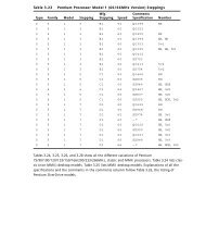
Table 2.4 shows the major Pentium-class CPUs made by companies<br />
other than Intel. The newest versions of these processors can often<br />
be used to upgrade an older Pentium—as long as proper voltage<br />
and system configuration information can be provided, either<br />
through adjusting the motherboard/BIOS settings or by purchasing<br />
an upgrade-type processor with third-party support.<br />
Footnotes for both tables follow Table 2.4.
22<br />
Chapter 2—System Components and Configuration<br />
Table 2.3 Intel Processor Specifications<br />
Internal<br />
Register Data Bus<br />
Processor CPU Clock Voltage Size Width<br />
8088 1x 5v 16-bit 8-bit<br />
8086 1x 5v 16-bit 16-bit<br />
286 1x 5v 16-bit 16-bit<br />
386SX 1x 5v 32-bit 16-bit<br />
386SL 1x 3.3v 32-bit 16-bit<br />
386DX 1x 5v 32-bit 32-bit<br />
486SX 1x 5v 32-bit 32-bit<br />
486SX2 2x 5v 32-bit 32-bit<br />
487SX 1x 5v 32-bit 32-bit<br />
486DX 1x 5v 32-bit 32-bit<br />
486SL 2 1x 3.3v 32-bit 32-bit<br />
486DX2 2x 5v 32-bit 32-bit<br />
486DX4 2–3x 3.3v 32-bit 32-bit<br />
486Pentium OD 2.5x 5v 32-bit 32-bit<br />
Pentium 60/66 1x 5v 32-bit 64-bit<br />
Pentium 75-200 1.5–3x 3.3-3.5v 32-bit 64-bit<br />
Pentium MMX 1.5–<br />
4.5x<br />
1.8–2.8v 32-bit 64-bit<br />
Pentium Pro 2–3x 3.3v 32-bit 64-bit<br />
Pentium II 3.5–<br />
4.5x<br />
1.8–2.8v 32-bit 64-bit<br />
Celeron 3.5–<br />
4.5x<br />
1.8–2.8v 32-bit 64-bit<br />
Celeron A 3.5–7x 1.8–2v 32-bit 64-bit<br />
Pentium II PE3 3.5–6x 1.6v 32-bit 64-bit<br />
Pentium II Xeon 4–4.5x 1.8–2.8v 32-bit 64-bit<br />
Pentium III Slot1 4.5–<br />
7.5x<br />
1.8–2v 32-bit 64-bit<br />
Pentium III PGA370 4–7x 1.8–2v 32-bit 64-bit<br />
Pentium III Xeon 5–6.5x varies 32-bit 64-bit
Intel and Compatible Processor Specifications 23<br />
L1 L2<br />
Max. Level 1 Cache L2 Cache Special<br />
Memory Cache Type Cache Speed Features<br />
1MB — — — — —<br />
1MB — — — — —<br />
16MB — — — — —<br />
16MB — — — Bus —<br />
16MB 0KB 1 WT — Bus —<br />
4GB — — — Bus —<br />
4GB 8KB WT — Bus —<br />
4GB 8KB WT — Bus —<br />
4GB 8KB WT — Bus FPU<br />
4GB 8KB WT — Bus FPU<br />
4GB 8KB WT — Bus FPU Opt.<br />
4GB 8KB WT — Bus FPU<br />
4GB 16KB WT — Bus FPU<br />
4GB 2x16KB WB — Bus FPU<br />
4GB 2x8KB WB — Bus FPU<br />
4GB 2x8KB WB — Bus FPU<br />
4GB 2x16KB WB — Bus FPU, MMX<br />
64GB 2x8KB WB 256KB,<br />
512KB,<br />
1MB<br />
Core FPU<br />
64GB 2x16KB WB 512KB 1/2<br />
Core<br />
FPU, MMX<br />
64GB 2x16KB WB 0KB — FPU, MMX<br />
64GB 2x16KB WB 128KB Core FPU, MMX<br />
64GB 2x16KB WB 256KB Core FPU, MMX<br />
64GB 2x16KB WB 512KB,<br />
1MB,<br />
2MB<br />
Core FPU, MMX<br />
64GB 2x16KB WB 512KB 1/2<br />
Core<br />
FPU, SSE<br />
64GB 2x16KB WB 256KB Core FPU, SSE<br />
64GB 2x16KB WB 512KB,<br />
1MB,<br />
2MB<br />
Core FPU, SSE
24<br />
Chapter 2—System Components and Configuration<br />
Table 2.4 Intel-Compatible Pentium-Class Processors<br />
Internal<br />
Register Data Bus Max.<br />
Processor CPU Clock Voltage Size Width Memory<br />
AMD K5 1.5–1.75x 3.5v 32-bit 64-bit 4GB<br />
AMD K6 2.5–4.5x 2.2–3.2v 32-bit 64-bit 4GB<br />
AMD K6-2 2.5–6x 1.9–2.4v 32-bit 64-bit 4GB<br />
AMD K6-3 3.5–4.5x 1.8–2.4v 32-bit 64-bit 4GB<br />
AMD Athlon 5–10x10 (nee K7)<br />
1.6–1.8v 32-bit 64-bit 8TB<br />
AMD Athlon, 5–10x10 with performance<br />
enhancing<br />
cache (PEC)<br />
(code name<br />
“Thunderbird”)<br />
1.8v 32-bit 64-bit 8TB<br />
AMD Duron9 6x–7.5x10 “Thunderbird”<br />
1.6–1.8v 32-bit 64-bit 8TB<br />
Cyrix 6x86 2x 2.5–3.5v 32-bit 64-bit 4GB<br />
Cyrix 6x86MX/MII 2–3.5x 2.2–2.9v 32-bit 64-bit 4GB<br />
VIA Cyrix III 2.5–7x 2.2v 32-bit 64-bit 4GB<br />
Nexgen Nx586 2x 4v 32-bit 64-bit 4GB<br />
IDT Winchip 3–4x 3.3–3.5v 32-bit 64-bit 4GB<br />
IDT Winchip2/2A 2.33–4x 3.3–3.5v 32-bit 64-bit 4GB<br />
Rise mP6 2–3.5x 2.8v 32-bit 64-bit 4GB<br />
FPU = Floating-Point unit (internal math coprocessor)<br />
WT = Write-through cache (caches reads only)<br />
WB = Write-back cache (caches both reads and writes)<br />
Bus = Processor external bus speed (motherboard speed)<br />
Core = Processor internal core speed (CPU speed)<br />
MMX = Multimedia extensions, 57 additional instructions for graphics and sound processing<br />
3DNow = MMX plus 21 additional instructions for graphics and sound processing<br />
SSE = Streaming SIMD (Single Instruction Multiple Data) Extensions, MMX plus 70 additional<br />
instructions for graphics and sound processing<br />
1. The 386SL contains an integral-cache controller, but the cache memory must be provided outside<br />
the chip.<br />
2. Intel later marketed SL Enhanced versions of the SX, DX, and DX2 processors. These processors<br />
were available in both 5v and 3.3v versions and included power-management capabilities.<br />
3. The Enhanced mobile PII has an on-die L2 cache similar to the Celeron.
Intel and Compatible Processor Specifications 25<br />
L1 L2<br />
Level 1 Cache Level 2 Cache Special<br />
Cache Type Cache Speed Features Similar to4 16+8KB WB — Bus FPU Pentium<br />
2x32KB WB — Bus FPU, MMX Pentium MMX<br />
2x32KB WB — Bus FPU, 3DNow Pentium MMX<br />
2x32KB WB 256KB Core FPU, 3DNow Pentium MMX<br />
2x64KB WB 512KB6 1/37 Core FPU, 3DNow Pentium III8 2x64KB WB 256KB Core FPU, 3DNow Pentium III<br />
2x64KB WB 64KB Core FPU, 3DNow Athlon PEC<br />
16KB WB — Bus FPU Pentium<br />
64KB WB — Bus FPU, MMX Pentium MMX<br />
64KB WB 256KB Core<br />
2x16KB WB — Bus FPU Pentium5 2x32KB WB — Bus FPU, MMX Pentium MMX<br />
2x32KB WB — Bus FPU, 3DNow AMD K6-2<br />
2x8KB WB — Bus FPU, MMX Pentium MMX<br />
4. These processors physically fit into the same Socket 7 used by Intel Pentium 75MHz and above<br />
models except as noted, but might require special chipsets or BIOS settings for best operation.<br />
Check with motherboard and chip mfr. before installing them in place of your existing<br />
Pentium-class chip.<br />
5. Pentium-class performance, but unique, non-standard pinout.<br />
6. Cache size for initial shipments (3rd Q 1999). Athlon designed it to allow cache sizes up to<br />
8MB.<br />
7. Athlon’s cache interface is designed to handle variable speed ratios, so later versions can run<br />
L2 cache more quickly.<br />
8. Athlon uses new AMD Slot A, physically similar to Slot 1 but with a different electrical pinout.<br />
9. Duron and “Thunderbird” versions of Athlon use new Socket A.<br />
10. Clock Multipliers listed based on 100MHz system bus (FSB) speeds; although Athlon and<br />
Duron use 200MHz bus, memory for these systems runs at PC100 or PC133 speeds, depending<br />
on the processor model.
26<br />
Chapter 2—System Components and Configuration<br />
Use Tables 2.5 and 2.6 to help determine which processors may fit<br />
in place of your existing CPU. Note that a replacement CPU must<br />
have the same pinout, the same electrical requirements, and be<br />
compatible with your motherboard. Many vendors sell upgradecompatible<br />
processor versions, which have been modified from<br />
their original forms by adding a voltage regulator and other support<br />
options.<br />
Table 2.5 Intel and Compatibles 486/Pentium-Class CPU Socket<br />
Types and Specifications<br />
Socket Supported<br />
Number Pins Pin Layout Voltage Processors<br />
Socket 1 169 17×17 PGA 5v 486 SX/SX2, DX/DX21 ,<br />
DX4 OverDrive<br />
Socket 2 238 19×19 PGA 5v 486 SX/SX2, DX/DX21 ,<br />
DX4 OverDrive, 486<br />
Pentium OverDrive<br />
Socket 3 237 19×19 PGA 5v/3.3v 486 SX/SX2, DX/DX2,<br />
DX4, 486 Pentium<br />
OverDrive, AMD 5x86,<br />
Cyrix 5x86<br />
Socket 4 273 21×21 PGA 5v Pentium 60/66,<br />
OverDrive<br />
Socket 5 320 37×37 SPGA 3.3/3.5v Pentium 75-133,<br />
OverDrive<br />
Socket 62 235 19×19 PGA 3.3v 486 DX4, 486 Pentium<br />
OverDrive<br />
Socket 7 321 37×37 SPGA VRM Pentium 75-233+, MMX,<br />
OverDrive, AMD K5/K6,<br />
Cyrix M1, VIA Cyrix MII<br />
Socket 8 387 dual pattern SPGA Auto VRM Pentium Pro<br />
PGA370 370 37×37 SPGA 2.0v Celeron, Pentium III, VIA<br />
Cyrix III<br />
Slot 1 242 Slot Auto VRM Pentium II/III, Celeron<br />
Slot 2 330 Slot Auto VRM Pentium II Xeon/<br />
Pentium III Xeon<br />
Slot A 242 Slot Auto VRM AMD Athlon (K7) SECC<br />
Socket A 462 SPGA Auto VRM AMD Duron/AMD<br />
Athlon PGA<br />
1. Non-overdrive DX4 or AMD 5x86 also can be supported with the addition of an aftermarket<br />
3.3v voltage-regulator adapter.<br />
2. Socket 6 was a paper standard only and was never actually implemented in any systems.<br />
PGA = Pin Grid Array.<br />
SPGA = Staggered Pin Grid Array.<br />
VRM = Voltage Regulator Module.
Table 2.6 lists the fastest processors you can install according to the<br />
socket type in your system. Note that newer socket designs allow<br />
faster processors, but that the bus speed and clock multiplier settings<br />
of your motherboard are also limiting factors for some CPU<br />
types.<br />
Table 2.6 Maximum Processor Speeds by Socket<br />
Socket Type Fastest Processor Supported<br />
Socket 1 5x86-133MHz with 3.3v adapter<br />
Socket 2 5x86-133MHz with 3.3v adapter<br />
Socket 3 5x86-133MHz<br />
Socket 4 Pentium OverDrive 133MHz<br />
Socket 5 Pentium MMX 233MHz or AMD K6 with 2.8v adapter<br />
Socket 7 AMD K6-2 up to 550MHz, K6-III up to 500MHz<br />
Socket 8 Pentium Pro OverDrive (333MHz Pentium II performance)<br />
Slot 1 Celeron 400MHz (66MHz bus)<br />
Slot 1 Pentium III 850MHz (100MHz bus)<br />
Slot 1 Pentium III 1.0GHz (133MHz bus)<br />
Slot 2 Pentium III Xeon 550MHz (100MHz bus)<br />
Slot 2 Pentium III Xeon 866MHz (133MHz bus)<br />
Socket 370 Celeron 600MHz (66MHz bus)<br />
Troubleshooting Processor Problems 27<br />
Socket 370 Pentium III 933MHz (100MHz bus)<br />
Slot A 1GHz AMD Athlon (K7) (200MHz bus), 1GHz AMD Athlon PEC<br />
(Thunderbird)<br />
Socket A 750MHz AMD Duron (200MHz bus), 1GHz AMD Athlon PEC<br />
(Thunderbird)<br />
Troubleshooting Processor<br />
Problems<br />
Table 2.7 provides a general troubleshooting checklist for processorrelated<br />
PC problems.
28<br />
Chapter 2—System Components and Configuration<br />
Table 2.7 Troubleshooting Processor-Related Problems<br />
Problem<br />
Identification Possible Cause Resolution<br />
System is dead, no Power cord failure. Plug in or replace power cord.<br />
cursor, no beeps, Power cords can fail even<br />
or no fan. though they look fine.<br />
Power supply Replace the power supply. Use<br />
failure. a known, good spare for testing.<br />
Motherboard Replace motherboard. Use a<br />
failure. known, good spare for testing.<br />
Memory failure. Remove all memory except one<br />
bank and retest. If the system still<br />
won’t boot, replace bank 1.<br />
System is dead, no All components Check all peripherals, especially<br />
beeps, or locks up either not installed memory and graphics adapter.<br />
before POST begins. or incorrectly installed.<br />
Reseat all boards and socketed<br />
components, such as CPUs and<br />
memory modules.<br />
System beeps on Improperly seated Reseat or replace graphics adapter.<br />
startup, fan is or failing graphics Use known, good spare for testing.<br />
running, no<br />
cursor onscreen.<br />
adapter.<br />
Locks up during Poor heat Check CPU heat sink/fan; replace if<br />
or shortly after dissipation. necessary, using one with a higher<br />
POST. capacity.<br />
Use thermal paste between<br />
fan/heatsink and CPU as directed<br />
by heatsink and CPU vendors.<br />
Improper voltage Set motherboard for proper core<br />
settings. processor voltage.<br />
Wrong motherboard<br />
bus speed.<br />
Set motherboard for proper speed.<br />
Wrong CPU clock Jumper motherboard for proper<br />
multiplier. clock multiplier.<br />
Improper CPU identification<br />
during POST.<br />
Old BIOS. Update BIOS from manufacturer.<br />
Board not Check manual and jumper board<br />
configured properly. according to proper bus and multiplier<br />
settings.<br />
If board is jumperless, adjust bus<br />
and multiplier in BIOS.
Table 2.7 Troubleshooting Processor-Related Problems Continued<br />
Problem<br />
Identification Possible Cause Resolution<br />
Operating system Poor heat Check CPU fan; replace if<br />
will not boot. dissipation. necessary. May need higher capacity<br />
heat sink and thermal paste.<br />
Improper voltage Jumper motherboard for proper<br />
settings. core voltage.<br />
Wrong motherboard Jumper motherboard or adjust<br />
bus speed. BIOS settings to correct speed.<br />
Wrong CPU clock Jumper motherboard or adjust<br />
multiplier. BIOS settings to correct multiplier.<br />
Applications will Improper drivers or incompatible<br />
not install or run. hardware. Update drivers and<br />
check for compatibility issues.<br />
System appears Monitor turned Check monitor and power to<br />
to work but no off or failed. monitor. Replace with knownvideo<br />
is displayed good spare for testing.<br />
If, during POST, the processor is not identified correctly, your<br />
motherboard settings might be incorrect or your BIOS might need<br />
to be updated. Check that the motherboard is jumpered or configured<br />
correctly for the processor that you have, and make sure that<br />
you have the latest BIOS for your motherboard.<br />
If the system seems to run erratically after it warms up, try setting<br />
the processor to a lower speed. If the problem goes away, the<br />
processor might be defective or overclocked.<br />
Many hardware problems are really software problems in disguise.<br />
Be sure you have the latest BIOS for your motherboard and the latest<br />
drivers for your peripherals. Also, it helps to use the latest version<br />
of your given operating system because, normally, fewer<br />
problems will occur.<br />
Note<br />
Motherboard Form Factors 29<br />
For more information about processors, see Chapter 3 of<br />
Upgrading and Repairing <strong>PCs</strong>, 12th Edition, also published by Que.<br />
Motherboard Form Factors<br />
Although many PC users have extended the life span of their systems<br />
by changing the CPU, any system that will be kept for a long<br />
time could be a candidate for a motherboard replacement. Use the<br />
following charts to determine whether your system uses one of
30<br />
Chapter 2—System Components and Configuration<br />
these standard form factors, which will allow you the choice of<br />
many vendors for a replacement. A replacement motherboard provides<br />
you with these benefits:<br />
• Access to faster, more advanced CPUs<br />
• “Free” updated BIOS with support for large hard drives; Y2K;<br />
and boot from LS-120, Zip, and CD-ROM drives<br />
• Newer I/O features, such as USB ports, UDMA-66 hard disk<br />
interfacing, and AGP video<br />
Baby-AT Motherboard<br />
Until mid-1996, this descendent of the original IBM/XT motherboard<br />
was the dominant design. Even though limited numbers of<br />
these motherboards are still available for use with both Pentiumclass<br />
and Pentium II/III/Celeron processors, the lack of built-in ports<br />
and cooling problems make this an obsolete design. If you are trying<br />
to upgrade a system that uses this motherboard design, consider<br />
purchasing a new ATX-style case, power supply, and motherboard.<br />
In addition, you should consider moving the CPU, RAM, drives, and<br />
cards from your existing system to the new box (see Figure 2.1).<br />
13.04"<br />
6.50"<br />
.34"<br />
.65"<br />
.45"<br />
3.75"<br />
.40"<br />
5.55"<br />
8.35"<br />
8.57"<br />
Figure 2.1 Baby-AT motherboard form factor dimensions.<br />
6.00"
LPX Motherboard<br />
Motherboard Form Factors 31<br />
Since 1987, many low-cost systems have used variations on this layout,<br />
which features a single slot used for a riser card. The expansion<br />
cards for video, audio, and so forth are connected to the riser card,<br />
not the motherboard. Most LPX systems use riser cards that mount<br />
the expansion slots parallel to the motherboard; some use a T-shaped<br />
riser card that keeps the expansion slots at their normal upright position.<br />
Additionally, most LPX systems have built-in video, audio, and<br />
other I/O ports. Unfortunately, because its details were never standardized,<br />
it is virtually impossible to upgrade. Systems with this<br />
motherboard are essentially disposable (see Figure 2.2).<br />
<br />
<br />
<br />
<br />
<br />
<br />
<br />
<br />
<br />
<br />
<br />
<br />
<br />
<br />
<br />
Figure 2.2 Typical LPX system chassis and motherboard.<br />
<br />
<br />
<br />
<br />
ATX Motherboard<br />
Since mid-1996, the ATX motherboard has become the standard<br />
for most systems using non-proprietary motherboards (see Figure<br />
2.3). Similar to Baby-AT, it’s also an industry standard, and similar<br />
to LPX, it features built-in ports. Compared to both, though, it<br />
offers much greater ease of upgrading and servicing. ATX motherboards<br />
are rotated 90 degrees when compared to Baby-ATs and also<br />
use a different power supply for advanced power management features.<br />
Because of their built-in ports and differences in layout, ATX<br />
motherboards require an ATX case. ATX cases can also be used for<br />
Baby-AT motherboards, though. Figure 2.3 shows a full-size ATX<br />
layout; however, several smaller versions now exist, including<br />
mini-ATX, micro-ATX, and flex-ATX.
32<br />
Chapter 2—System Components and Configuration<br />
Double high<br />
expandable I/O<br />
Full<br />
length slots<br />
Floppy/IDE<br />
connectors close<br />
to peripheral bays<br />
Figure 2.3 ATX system chassis layout and features.<br />
NLX Motherboard<br />
3 1/2"<br />
Bay<br />
Processor<br />
Single<br />
chassis fan<br />
CPU located<br />
near PSU<br />
Single power<br />
connector<br />
Easy to access<br />
SIMM memory<br />
The replacement for the old LPX low-profile motherboard is the<br />
NLX motherboard (see Figure 2.4). NLX also features built-in ports<br />
and a riser card, but its standard design means that replacement<br />
motherboards should be easier to purchase than those for LPX systems.<br />
A major advantage of NLX systems is that the motherboard is<br />
easy to remove for servicing through a side panel, a feature that<br />
makes NLX-based systems popular as corporate network client <strong>PCs</strong>.<br />
5 1/4"<br />
Bay<br />
Power<br />
Supply<br />
Figure 2.4 NLX motherboard and riser combination.<br />
Which Motherboard Is Which?<br />
Use Table 2.8 to help determine whether a system is a Baby-AT, an<br />
LPX, an ATX, or an NLX-based system.
Table 2.8 Comparison of Major Motherboard Form Factors<br />
Baby-AT LPX<br />
ATX/<br />
Micro ATX1 NLX WTX<br />
Ports built No Yes Yes Yes No2 into chassis<br />
Riser card No Yes No Yes No<br />
Single row of<br />
ports at rear<br />
N/A Yes No No No<br />
Two rows of N/A No Yes Yes No3 ports at rear<br />
Slots on both<br />
sides of riser<br />
card<br />
N/A Opt N/A No N/A<br />
Riser card N/A Middle N/A Side near N/A<br />
location power<br />
on MB supply<br />
1. MicroATX motherboards can fit into ATX cases, but have fewer slots and are designed for<br />
socketed, rather than slot-based, processors. They also usually feature onboard audio and<br />
video, both of which are usually optional on ATX motherboards.<br />
2. WTX supports a FlexSlot design, which uses a single modified PCI slot for all standard ports.<br />
3. The layout of ports on the rear of a FlexSlot resembles the layout on the rear of an ATX or a<br />
MicroATX motherboard, but they are vertically oriented because they are attached to a<br />
FlexSlot. See www.wtx.org for more information.<br />
PC99 Color-Coding for Ports<br />
Microsoft and Intel have developed the following standardized<br />
color-coding of connectors for computers compliant with the PC99<br />
design standards. Use Table 2.9 to help you match non–color-coded<br />
peripherals with the correct external ports.<br />
Note<br />
Some systems, especially those built before 1999, might use a<br />
proprietary color scheme for ports.<br />
Check the inside front and back covers of this book for pictures of<br />
these ports. For color samples, see the following Web site:<br />
http://www.pcdesguide.com/documents/pc99icons.htm<br />
Table 2.9 PC99 Color-Coding Standards for Ports<br />
Port Type Color<br />
Analog VGA (DB15) Blue<br />
Audio line in Light blue<br />
Audio line out Lime green<br />
Digital monitor White<br />
PC99 Color-Coding for Ports 33
34<br />
Chapter 2—System Components and Configuration<br />
Table 2.9 PC99 Color-Coding Standards for Ports Continued<br />
Port Type Color<br />
IEEE-1394 (i.Link, FireWire) Grey<br />
Microphone Pink<br />
MIDI/Gameport Gold<br />
Parallel port Burgundy<br />
Serial port Teal or turquoise<br />
Speaker out (subwoofer) Orange<br />
Right-to-left speaker Brown<br />
USB Black<br />
Video out Yellow<br />
SCSI, network, telephone,<br />
modem, and so on<br />
None<br />
Power Supplies<br />
Power supplies actually convert high-voltage AC (alternating current)<br />
into low-voltage DC (direct current) for use by <strong>PCs</strong>. Power<br />
supplies come in several form factors, and they also feature various<br />
motherboard connectors to correspond with the newer motherboard<br />
designs on the market. Table 2.10 illustrates which power<br />
supplies are most likely to be used with various motherboards.<br />
Table 2.10 Matching Power Supplies and Motherboards<br />
Motherboard Most Common PS Other PS Form<br />
Form Factor Form Factor Used Factors Used<br />
Baby-AT LPX style Baby-AT, AT/Tower,<br />
or AT/Desk<br />
LPX LPX style None<br />
ATX ATX style None<br />
MicroATX ATX style SFX style<br />
NLX ATX style None<br />
LPX Versus ATX Power Supplies<br />
Some motherboards are designed to handle either LPX or ATX<br />
power supplies. The ATX is the preferred design because it provides<br />
the lower voltage needed by today’s CPUs, offers foolproof installation,<br />
and also provides better cooling than older designs.<br />
Table 2.11 compares two of the more common power supply form<br />
factors used in computers today, and Figure 2.5 shows an LPX<br />
power supply.
Table 2.11 Comparing ATX and LPX Power Supplies<br />
Power Supplies 35<br />
Power Motherboard<br />
Supply Voltage Power Other<br />
Type Output Connectors Features Notes<br />
LPX 5v, 12v 2–6 pins Easy to reverse the<br />
each (P8/P9) plug due to poor keying<br />
ATX 3.3v, 5v, 12v 1–20 pins Keyed to go in only one<br />
way; allows hibernation via<br />
operating system or keyboard<br />
command<br />
86mm<br />
6mm<br />
64mm<br />
86mm<br />
16mm<br />
5 138mm<br />
7<br />
+<br />
+<br />
5 115mm<br />
150mm<br />
Figure 2.5 LPX form factor power supply.<br />
140mm<br />
+<br />
+<br />
30mm<br />
+5V<br />
G<br />
G<br />
+12V<br />
+5V<br />
G<br />
G<br />
+12V<br />
+5V<br />
G<br />
G<br />
+12V<br />
Table 2.12 breaks down the typical LPX power supply connector.<br />
6<br />
+5V<br />
G<br />
G<br />
+12V<br />
P.G.<br />
+5V<br />
+12V<br />
-12V<br />
G<br />
G<br />
G<br />
G<br />
-5V<br />
+5V<br />
+5V<br />
+5V
36<br />
Caution<br />
Chapter 2—System Components and Configuration<br />
To get the cables oriented correctly, keep the ground wires<br />
(black) next to each other. Although most connectors are keyed<br />
to prevent improperly plugging them in, some connectors can<br />
easily be inserted incorrectly. This will cause your motherboard<br />
to be destroyed the first time you switch on the power and<br />
could possibly cause a fire.<br />
Table 2.12 Typical LPX Power Supply Connections<br />
Connector Voltage Standard Color/Notes<br />
P8-1 Power_Good (+5v) Orange<br />
P8-2 +5v Red<br />
P8-3 +12v Yellow<br />
P8-4 -12v Blue<br />
P8-5 Ground (0) Black<br />
P8-6 Ground (0) Black<br />
P9-1 Ground (0) Black<br />
P9-2 Ground (0) Black<br />
P9-3 -5v White<br />
P9-4 +5v Red<br />
P9-5 +5v Red<br />
P9-6 +5v Red<br />
Power Connectors for the Drive(s)<br />
The connectors shown in Table 2.13 might not be labeled, but they<br />
easily can be distinguished by the four-wire cable and color-coding.<br />
The same colors are used for drive power connectors on ATX power<br />
supplies. Figure 2.6 shows an ATX power supply.<br />
Table 2.13 ATX Power Supply Color Coding<br />
Connector Voltage Standard Color/Notes<br />
P10-1 +12v Yellow<br />
P10-2 Ground (0) Black<br />
P10-3 Ground (0) Black<br />
P10-4 +5v Red
86mm<br />
6mm<br />
64mm<br />
86mm<br />
16mm<br />
5 138mm<br />
7<br />
+<br />
+<br />
140mm<br />
5 115mm<br />
150mm<br />
+<br />
+<br />
30mm<br />
6<br />
+5V<br />
G<br />
G<br />
+12V<br />
+5V<br />
G<br />
G<br />
+12V<br />
+5V<br />
G<br />
G<br />
+12V<br />
+5V<br />
G<br />
G<br />
+12V<br />
Power Supplies 37<br />
3.3V*<br />
11 1<br />
3.3V*<br />
12 2<br />
-12V<br />
3.3V*<br />
13 3<br />
COM<br />
COM<br />
14 4<br />
PS-ON<br />
5V<br />
15 5<br />
COM<br />
COM<br />
16 6<br />
COM<br />
5V<br />
17 7<br />
COM<br />
COM<br />
18 8<br />
-5V<br />
PW-OK<br />
5V<br />
19 9<br />
5VSB<br />
20 10<br />
5V<br />
12V<br />
*optional<br />
ATX Power connector pin out<br />
Figure 2.6 ATX form factor power supply used with both ATX and NLX<br />
systems. The pinout for the motherboard power is shown at lower right.<br />
Note the single square pin used for keying.<br />
Table 2.14 shows the pinout for the ATX motherboard power connector.<br />
Table 2.14 ATX Motherboard Power Supply Connections<br />
Color Signal Pin Pin Signal Color<br />
Orange +3.3v 11 1 +3.3v Orange<br />
Blue -12v 12 2 +3.3v Orange<br />
Black GND 13 3 GND Black<br />
Green PS_On 14 4 +5v Red<br />
Black GND 15 5 GND Black<br />
Black GND 16 6 +5v Red<br />
Black GND 17 7 GND Black<br />
White -5v 18 8 Power_Good Grey<br />
Red +5v 19 9 +5VSB<br />
(Standby)<br />
Purple<br />
Red +5v 20 10 +12v Yellow<br />
Quick-Reference Chart for Troubleshooting Power<br />
Supplies<br />
Table 2.15 Troubleshooting Power Supplies<br />
Symptom Cause(s) Tests and Solution(s)<br />
Overheating. Inadequate system cooling Check ventilation around system;<br />
clean system internally; check for<br />
missing slot covers.<br />
Higher load on system in Replace power supply with higher<br />
watts than power supply rated unit.<br />
rating
38<br />
Table 2.15 Troubleshooting Power Supplies Continued<br />
Symptom Cause(s) Tests and Solution(s)<br />
System reboots Incorrect power level on Use DC-voltage digital multimeter<br />
itself. Power_Good; can indicate (DMM) to test P8-1 (orange wire)<br />
overloaded power supply on LPX and older power supplies<br />
or otherwise bad unit or Pin 8 (gray wire) on ATX and<br />
newer power supplies; rated voltage<br />
is +5v; acceptable is +3.0v to<br />
+6.0v.<br />
Replace failed power supply with<br />
higher rated unit.<br />
Fan turns for Wrong voltage (PS set to Turn off system; reset PS to<br />
only a moment 220/230v in U.S.) correct voltage (110/115v in<br />
and then stops. U.S.) and restart. Using 220/230v<br />
power on a PS set for 110/115v<br />
will destroy it!<br />
Dead short in system Short can be caused by loose<br />
screws, failed hard drives, or addon<br />
cards.<br />
Turn off and unplug system; disconnect<br />
hard drive and see<br />
whether system starts. If system<br />
still fails, plug in drive and remove<br />
add-on card; repeat until each<br />
card and drive has been checked;<br />
also check Y-adapter cables<br />
because bad cables can cause<br />
shorts.<br />
Note<br />
Chapter 2—System Components and Configuration<br />
Replace faulty component(s).<br />
For more information on power supplies, wattage ratings, and<br />
testing, see Chapter 21 of Upgrading and Repairing <strong>PCs</strong>, 12th<br />
Edition, published by Que.<br />
Memory Types<br />
RAM (random access memory) provides the work area that processors<br />
use to create and modify data. While RAM was sometimes<br />
found on expansion boards on old XT-class and early AT-class systems,<br />
all standard 486-based and Pentium-class systems have their<br />
memory modules attached to the motherboard.<br />
Memory modules come in two major forms: SIMMs and DIMMs.<br />
SIMM stands for single-sided inline memory module, and DIMM<br />
stands for dual-sided inline memory module. These terms refer to<br />
the pin configurations used on the module, rather than the location<br />
of the memory chips on the module.
The following features are common to all SIMMs:<br />
• Pins numbered from left to right<br />
• Same pins on both sides of the module<br />
Memory Types 39<br />
Tip<br />
Note that all dimensions for both SIMMs and DIMMs in the following<br />
figures are in both inches and millimeters (in parentheses).<br />
30-Pin SIMM<br />
The 30-pin SIMM is the oldest type of memory module still in use<br />
(see Figure 2.7). It was popular on 386-based and early 486-based<br />
systems, but became obsolete with the rise of Pentium-class 64-bit<br />
CPUs. Although its capacities are extremely small compared to<br />
more modern memory designs, its unpopularity since the early<br />
1990s makes the 30-pin SIMM the most expensive memory type<br />
per megabyte. If you are still supporting systems that use this type<br />
of module, look for sources of used memory or replace the motherboard<br />
with one that uses newer, 72-pin SIMM or DIMM memory<br />
instead of buying new 30-pin modules.<br />
.250 (6.35)<br />
TYP.<br />
.080 (2.03)<br />
TYP.<br />
PIN 1<br />
3.505 (89.03)<br />
3.495 (88.77)<br />
.100 (2.54)<br />
TYP.<br />
.400 (10.16)<br />
TYP.<br />
.070 (1.78)<br />
TYP.<br />
.653 (16.59)<br />
.647 (16.43)<br />
.133 (3.38)<br />
TYP.<br />
.055 (1.40)<br />
.047 (1.19)<br />
.200 (5.08)<br />
MAX.<br />
Figure 2.7 A typical 30-pin SIMM. The one shown here is 9-bit,<br />
although the dimensions would be the same for 8-bit.<br />
72-Pin SIMM<br />
The 72-pin SIMM was the most popular for a number of years, but<br />
has now been superseded on newer systems by DIMM modules. 72pin<br />
SIMMs are commonly found on late-model 486-based systems,<br />
most Pentiums, and most early Pentium-compatible systems.<br />
Because these modules are also becoming very expensive per<br />
megabyte, try to salvage or swap memory to populate older systems<br />
rather than purchase new. 72-pin SIMMs can be either fast-page or<br />
extended data out (EDO). 486-class systems can use only fast-page<br />
SIMMs, but Pentium-class systems that use SIMMs can use either<br />
type. Fast-page and EDO SIMMs should not be mixed. Some
40<br />
Chapter 2—System Components and Configuration<br />
systems require BIOS configuration to optimize performance if you<br />
install EDO memory (see Figure 2.8).<br />
.125 (3.18)<br />
TYP<br />
.250<br />
(6.35)<br />
.080 (2.03)<br />
PIN 1<br />
1.75 (44.45) TYP<br />
4.260 (108.20)<br />
4.240 (107.70)<br />
.250 (6.35)<br />
3.75 (95.25)<br />
Figure 2.8 A typical 72-pin SIMM, although the dimensions would be<br />
the same for 32-bit.<br />
DIMMs<br />
DIMMs became popular with the rise of the Pentium II/III/Celeron<br />
family of processors—AMD’s Athlon series—and can also be found<br />
on many late-model Pentium and “Super Socket 7” motherboards<br />
used with AMD K6-series and Cyrix 6x86MX/MII processors (see<br />
Figure 2.9). DIMMs are the most popular and fastest type of memory<br />
module in widespread use. Most DIMMs are Synchronous<br />
DRAM (SDRAM). On motherboards with both SIMM and DIMM<br />
sockets, SDRAMs cannot be used in conjunction with SIMMs, but<br />
the relatively rare EDO DIMMs can be used along with EDO<br />
SIMMs.<br />
.050 (1.27)<br />
TYP<br />
The following features are common to all DIMMs:<br />
• Three edge connectors of varying widths for positive keying<br />
.040 (1.02)<br />
TYP<br />
• Different pinouts on each side of the DIMM<br />
.079 (2.00) R<br />
(2X)<br />
.118 (3.00) R<br />
(2X)<br />
.118 (3.00) TYP<br />
.118 (3.00)<br />
TYP<br />
FRONT VIEW<br />
5.260 (133.80)<br />
5.240 (133.00)<br />
.250 (6.35) TYP<br />
1.661 (42.18)<br />
.039 (1.00)R (2X)<br />
.39 (1.27)<br />
2.625 (66.68)<br />
TYP<br />
PIN 1 (PIN 85 ON BACKSIDE)<br />
4.550 (115.57)<br />
.050 (1.27)<br />
TYP<br />
+<br />
.133 (3.38)<br />
TYP<br />
.235 (5.97)<br />
MIN<br />
1.010 (25.65)<br />
.990 (25.15)<br />
.400 (10.16)<br />
TYP<br />
– 1.260 (32.00)<br />
1240 (31.50)<br />
.700 (17.7B)<br />
TYP<br />
.128 (3.25)<br />
.118 (3.00) (2x)<br />
PIN 84 (PIN 168 ON BACKSIDE)<br />
.350 (8.98)<br />
MAX<br />
.054 (1.37)<br />
.047 (1.19)<br />
.350 (8.89)<br />
MAX<br />
.054 (1.37)<br />
.046 (1.17)<br />
Figure 2.9 A typical 168-pin DIMM. The one shown here is 72-bit,<br />
although the dimensions would be the same for 64-bit.<br />
RDRAM<br />
The RDRAM, or Rambus DRAM, is a radical new memory design that<br />
is slowly appearing in high-end PC systems that use Intel chipsets.<br />
RDRAM differs from previous memory devices in that it provides<br />
multiple high-speed (800MHz), narrow-channel (16-bit–wide) data
Memory Types 41<br />
transfers to and from a 128-bit memory bus instead of the slower<br />
(100MHz or 66MHz), 32-bit or 64-bit data transfers of SDRAM and<br />
previous memory types.<br />
RDRAM modules are called RIMMs (Rambus Inline Memory Module),<br />
and any unused RIMM slots on a motherboard must be filled with<br />
a continuity module to permit a continuous high-speed data pathway<br />
through the RIMMs (see Figure 2.10). Each RIMM represents<br />
multiple memory banks, and thus a single RIMM at a time can be<br />
added to a system—much the way installation of DIMMs works,<br />
although the memory types are not interchangeable.<br />
1.00 [0.039] 3.00 [0.118]<br />
Detail A<br />
4.00 [0.157]<br />
5.675 [0.2234]<br />
REF.<br />
A-1<br />
+<br />
COMPONENT AREA<br />
(A SIDE)<br />
+<br />
B-1<br />
133.35 +0.15<br />
-0.15 5.250+0.006<br />
-0.006<br />
+<br />
Detail B<br />
1.00[0.039]<br />
11.50[0.453]<br />
4.50[1.772]<br />
45.00[1.777]<br />
27.50[1.083]<br />
45.00[1.772]<br />
+0.08<br />
55.18<br />
-0.08<br />
78.17[3.078]<br />
REF.<br />
2.172+0.003<br />
-0.003<br />
-A-<br />
+<br />
+<br />
COMPONENT AREA<br />
(B SIDE)<br />
+<br />
+<br />
+<br />
B-92<br />
17.78 [0.700]<br />
0.85 [0.033]<br />
4.00 +0.15<br />
-0.15 0.157+0.006<br />
-0.006<br />
-B-<br />
A-92<br />
1.27 +0.10<br />
-0.10<br />
0.050 +0.004<br />
-0.004<br />
+0.10<br />
3.00<br />
-0.10<br />
0.80 +0.10<br />
Detail B<br />
-0.10<br />
TYP. 184 PLCS<br />
0.15 +0.10<br />
-0.10<br />
3XScale<br />
2.99 +0.05<br />
-0.05<br />
Capacitor<br />
CSP<br />
Note: Components<br />
Not Always Present<br />
on B side<br />
0.75-1.35<br />
[0.030-0.053]<br />
-C-<br />
+<br />
3XScale<br />
Figure 2.10 Typical RDRAM bus layout, showing two RIMMs and one<br />
continuity module installed.<br />
DDR SDRAM<br />
Double Data Rate (DDR) SDRAM memory is an improved version of<br />
standard SDRAM in which data is transferred twice as fast. Instead<br />
of doubling the actual clock rate, DDR memory achieves the doubling<br />
in performance by transferring twice per transfer cycle—once<br />
at the leading (falling) and once at the trailing (rising) edge of the<br />
cycle. This is similar to the way RDRAM operates and effectively<br />
doubles the transfer rate, even though the same overall clock and<br />
timing signals are used.<br />
DDR SDRAM is supported by many of the newest server chipsets<br />
and provides a design alternative to the more radical RDRAM. The<br />
DDR Consortium—an industry panel consisting of Fujitsu, Ltd.;<br />
Hitachi, Ltd.; Hyundai Electronics Industries Co.; Mitsubishi<br />
Electric Corp.; NEC Corp.; Samsung Electronics Co.; Texas<br />
Instruments, Inc.; and Toshiba Corp.—undertook official standardization<br />
of DDR.<br />
2.00 +0.10<br />
-0.10<br />
3.99 +0.10<br />
-0.10<br />
DDR-SDRAM uses a new DIMM module design with 184 pins.<br />
Figure 2.11 shows the DDR SDRAM DIMM.
42<br />
Chapter 2—System Components and Configuration<br />
Startup and<br />
observe POST.<br />
If errors are<br />
encountered,<br />
go to defect<br />
isolation<br />
procedures.<br />
Defect<br />
Isolation<br />
Procedures.<br />
If count does<br />
not match, go to<br />
defect isolation<br />
procedures.<br />
If problems are<br />
encountered, go<br />
to Defect Isolation<br />
Procedures.<br />
If POST completes<br />
with no errors,<br />
basic functionality<br />
has been tested.<br />
Restart system,<br />
enter Bios (or CMOS)<br />
setup. Verify that<br />
memory count is<br />
equal to installed<br />
amount.<br />
While in the BIOS,<br />
set all cache options<br />
to disabled, save<br />
settings and boot to<br />
a DOS formatted<br />
(floppy) system disk.<br />
Use a diagnostics<br />
program to test<br />
system base and<br />
extended memory.<br />
If no problems are<br />
encountered, memory<br />
has tested OK.<br />
Reboot, enter BIOS<br />
setup re-enable.<br />
Figure 2.11 184-pin DDR (Double Data Rate) SDRAM DIMM.<br />
DDR DIMMs are rated for either PC200 (100MHz x 2) or PC266<br />
(133MHz x 2) operation and normally run on 2.5 volts. They are<br />
basically an extension of the PC100 and PC133 DIMMs redesigned<br />
to support double clocking, where data is sent on each clock transition<br />
(twice per cycle) rather than once per cycle as is standard with<br />
SDRAM.<br />
Parity Versus Non-Parity Memory<br />
Parity-checked RAM uses units of 8 memory bits plus 1 parity bit,<br />
for a total of 9 bits. In addition, parity checking uses both the data<br />
bits and the parity bit to ensure that memory contents are accurate<br />
with each memory access.<br />
Virtually all 386-based and older systems, and most 486-based systems,<br />
require parity-checked memory, which can detect, but not<br />
correct, memory errors. On the other hand, most Pentium-class
and higher systems don’t require parity-checked RAM, but will<br />
ignore the parity bit(s) if present.<br />
Parity-checked memory must be used on systems that require it,<br />
and should be used on systems that can be configured to use the<br />
parity bits, especially if the systems support ECC (Error Correction<br />
Code) operation, which uses the parity bit as a means of correcting a<br />
faulty memory bit.<br />
Requirements for ECC Memory Use<br />
ECC requires the following:<br />
• Parity-checked memory modules<br />
• A motherboard chipset that offers ECC support<br />
• ECC support enabled in the BIOS system configuration<br />
ECC operation is recommended for servers and other systems that<br />
are performing mission-critical tasks because ECC operation can<br />
correct single-bit memory errors. Larger memory errors will cause<br />
the system to display an error message and halt.<br />
However, systems using ECC will cost more due to the higher cost<br />
of parity-checked RAM. Additionally, system performance is slightly<br />
slower due to the extra time involved in ECC operation. Check<br />
your motherboard or system documentation to determine whether<br />
ECC is an option for your system.<br />
To determine whether a memory module supports parity-checking<br />
or ECC, use the following tips.<br />
Using the Divide by 3 Rule to Determine Parity Support<br />
Count the chips on a SIMM or DIMM. If you can divide the number<br />
of chips by 3, the module is most likely a parity-checked module.<br />
However, some memory manufacturers have created memory<br />
modules with fake parity chips; these are referred to as logic parity<br />
modules.<br />
Note<br />
Memory Types 43<br />
See Upgrading and Repairing <strong>PCs</strong>, 12th Edition, Chapter 6, for<br />
more information about how to detect a logic parity module.<br />
Using the Divide by 9 Rule to Determine Parity Support<br />
A similar “divide by 9” rule can also be used to determine parity<br />
checking if you know the number of memory bits in the module.<br />
Note in Table 2.16 that the number of bits in parity-checked
44<br />
modules can be divided by 9, but the number of bits in non-parity<br />
modules can be divided only by 8.<br />
Table 2.16 SIMM and DIMM Capacities<br />
30-Pin SIMM Capacities<br />
Capacity Parity SIMM Non-Parity SIMM<br />
256KB 256KB×9 256KB×8<br />
1MB 1MB×9 1MB×8<br />
4MB 4MB×9 4MB×8<br />
16MB 16MB×9 16MB×8<br />
72-Pin SIMM Capacities<br />
Capacity Parity SIMM Non-Parity SIMM<br />
1MB 256KB×36 256KB×32<br />
2MB 512KB×36 512KB×32<br />
4MB 1MB×36 1MB×32<br />
8MB 2MB×36 2MB×32<br />
16MB 4MB×36 4MB×32<br />
32MB 8MB×36 8MB×32<br />
64MB 16MB×36 16MB×32<br />
128MB 32MB×36 32MB×32<br />
168-Pin DIMM Capacities<br />
Chapter 2—System Components and Configuration<br />
Capacity Parity DIMM Non-Parity DIMM<br />
8MB 1MB×72 1MB×64<br />
16MB 2MB×72 2MB×64<br />
32MB 4MB×72 4MB×64<br />
64MB 8MB×72 8MB×64<br />
128MB 16MB×72 16MB×64<br />
256MB 32MB×72 32MB×64<br />
Expanding Memory on a System<br />
Memory must be added to a system in banks. Simply put, a bank of<br />
memory is the amount of RAM in bits equal to the data bus width<br />
of the computer’s CPU (see Table 2.17). Thus, a Pentium’s data bus<br />
is 64 bits, and a memory module(s) used with a Pentium must have<br />
a total width of 64 bits for non-parity memory and 72 bits for<br />
parity-checked or ECC memory.
Table 2.17 Memory Bank Widths on Various Systems<br />
Memory Types 45<br />
30-Pin 72-Pin 168-Pin<br />
Memory Memory SIMMs SIMMs SIMMs<br />
Data Bank Size Bank Size per per per<br />
Processor Bus (No Parity) (Parity) Bank Bank Bank<br />
8088 8-bit 8 bits 9 bits 1 n/a n/a<br />
8086 16-bit 16 bits 18 bits 2 n/a n/a<br />
286 16-bit 16 bits 18 bits 2 n/a n/a<br />
386SX,<br />
SL, SLC<br />
16-bit 16 bits 18 bits 2 n/a n/a<br />
386DX 32-bit 32 bits 36 bits 4 1 n/a<br />
486SLC,<br />
SLC2<br />
16-bit 16 bits 18 bits 2 n/a n/a<br />
486SX,<br />
DX, DX2,<br />
DX4, 5x86<br />
32-bit 32 bits 36 bits 4 1 n/a<br />
Pentium, 64-bit 64 bits 72 bits 8 1<br />
K5, K6<br />
6x86,<br />
6x86MX,<br />
MII<br />
2 1<br />
Pentium 64-bit 64 bits 72 bits 8 1<br />
Pro, PII,<br />
PIII, Celeron,<br />
Xeon, AMD<br />
Athlon,<br />
Duron, Intel<br />
Itanium<br />
2 1<br />
1. Very few motherboards for these processors actually use this type of memory.<br />
The number of bits for each bank can be made up of single chips, SIMMs, or DIMMs. Modern<br />
systems don’t use individual chips; instead, they use only SIMMs or DIMMs. If the system has a<br />
16-bit processor, such as a 386SX, it probably uses 30-pin SIMMs and has two SIMMs per bank.<br />
All the SIMMs in a single bank must be the same size and type.<br />
Memory Troubleshooting<br />
Figure 2.12 provides basic steps that enable you to effectively test<br />
and troubleshoot your system RAM. First, let’s cover the memory<br />
testing and troubleshooting procedures.<br />
After you’ve determined that the system’s memory is defective, you<br />
need to determine which memory module is at fault. Follow the<br />
procedure in Figure 2.13 to isolate the module for replacement.
46<br />
Chapter 2—System Components and Configuration<br />
Restart system and<br />
enter BIOS setup under<br />
advanced or chipset<br />
setup, select memory<br />
timing parameters and<br />
set all to BIOS defaults.<br />
Save settings and reboot.<br />
Retest as shown in<br />
Figure 6.17.<br />
Problem<br />
not solved<br />
Open your system case.<br />
Identify the SIMMS/<br />
DIMMS/RIMMS.<br />
Determine the bank<br />
arrangement. Remove<br />
and reinstall all of the<br />
memory modules to<br />
reseat them. Ensure that<br />
they are the correct size,<br />
speed, voltage, and type<br />
for your system.<br />
If problem remains with<br />
all but 1st bank removed,<br />
problem isolated to 1st<br />
bank. Replace memory<br />
modules.<br />
Problem solved<br />
Problem solved<br />
If problem does not<br />
recur after removing/<br />
replacing modules, could<br />
be that contacts need<br />
cleaned.<br />
Problem<br />
not solved<br />
Problem solved<br />
Figure 2.12 Testing and troubleshooting memory.<br />
Memory Usage Within the System<br />
Note which are the<br />
slowest.<br />
If problem was solved,<br />
the improper BIOS<br />
settings were the culprit.<br />
If problem is solved with<br />
all but bank 1 removed,<br />
the problem could be in<br />
one of the modules you<br />
removed. Add 1 at a time,<br />
and retest. When problem<br />
appears, replace module.<br />
If problem still remains<br />
after all banks are tested,<br />
replace motherboard.<br />
The original PC had a total of 1MB of addressable memory, and the<br />
top 384KB of that was reserved for use by the system. Placing this<br />
reserved space at the top (between 640KB and 1,024KB instead of at<br />
the bottom, between 0KB and 640KB) led to what is often called the<br />
conventional memory barrier. Systems with more than 1MB of RAM<br />
treat the additional RAM as extended memory, beginning at 1MB.<br />
Thus, there is a “hole” in memory usage between 640KB and 1MB.<br />
Some standard add-on cards and motherboard devices use part of<br />
this memory area for RAM and ROM addresses, leaving the remainder<br />
of this space free for additional card usage.<br />
Hardware and Firmware Devices That Use Memory<br />
Addresses<br />
The listing of hardware and firmware devices that use memory<br />
addresses is relatively short when compared to IRQ, DMA, and I/O<br />
port address usage, but it is no less important. No two devices can<br />
share a memory address. Table 2.18 shows memory usage in the<br />
640KB–1MB memory range for standard devices.
Startup and<br />
observe POST.<br />
If errors are<br />
encountered,<br />
go to defect<br />
isolation<br />
procedures.<br />
Defect<br />
Isolation<br />
Procedures<br />
If count does<br />
not match, go to<br />
defect isolation<br />
procedures.<br />
If problems are<br />
encountered, go<br />
to Defect Isolation<br />
Procedures.<br />
Figure 2.13 Follow these steps if you are still encountering memory<br />
errors after completing the steps in Figure 2.12.<br />
Table 2.18 Memory Usage in the 640KB–1MB Range<br />
Device Address Range Notes<br />
Graphics Mode<br />
Video RAM<br />
0A0000–0AFFFF<br />
Monochrome Text<br />
Mode Video RAM<br />
0B0000–0B7FFF<br />
Color Text Mode<br />
Video RAM<br />
0B8000–0BFFFF<br />
Video ROM for<br />
VGA, Super VGA<br />
0C0000–0C7FFF<br />
Memory Types 47<br />
If POST completes<br />
with no errors,<br />
basic functionality<br />
has been tested.<br />
Restart system,<br />
enter BIOS (or CMOS)<br />
setup. Verify that<br />
memory count is<br />
equal to installed<br />
amount.<br />
While in the BIOS,<br />
set all cache options<br />
to disabled, save<br />
settings and boot to<br />
a DOS formatted<br />
(floppy) system disk.<br />
Use a diagnostics<br />
program to test<br />
system base and<br />
extended memory.<br />
If no problems are<br />
encountered, memory<br />
has tested OK.<br />
Reboot, enter BIOS<br />
setup re-enable.
48<br />
Chapter 2—System Components and Configuration<br />
Table 2.18 Memory Usage in the 640KB–1MB Range Continued<br />
Device Address Range Notes<br />
Unassigned 0C8000–0DFFFF Available for use by BIOS or<br />
RAM chips on add-on cards<br />
or by memory managers,<br />
such as QEMM or EMM386<br />
Motherboard ROM 0E0000–0EFFFF If not used by BIOS<br />
BIOS extension extensions, can be<br />
(IBM PS/2s, most treated as<br />
Pentium-class additional<br />
and newer systems) unassigned space<br />
Motherboard ROM<br />
BIOS (all systems)<br />
0F0000–0FFFFF<br />
If you are using an add-on card that uses a ROM BIOS chip<br />
onboard to overcome IDE hard drive limitations, overcome Y2K<br />
date rollover problems, or provide support for bootable SCSI hard<br />
drives, the BIOS chips on those cards must be placed in the unassigned<br />
memory range listed earlier. If you have two or more add-on<br />
cards that use memory address ranges, for best system performance,<br />
set the cards to use adjacent memory addresses.<br />
Table 2.19 shows the typical memory uses for some common IDE<br />
and SCSI interface cards that use ROM BIOS chips.<br />
Table 2.19 Memory Addresses Used by Various Adapter Cards<br />
Adapter Type Onboard BIOS Size BIOS Address Range<br />
Most XT compatible<br />
controllers<br />
8KB 0C8000–0C9FFF<br />
Most AT controllers None Drivers in motherboard BIOS<br />
Most standard IDE<br />
hard disk adapters<br />
None Drivers in motherboard BIOS<br />
Most enhanced1 IDE hard disk adapters<br />
16KB 0C8000–0CBFFF<br />
Some SCSI host adapters 16KB 0C8000–0CBFFF<br />
Some SCSI host adapters 16KB 0DC000–0DFFFF<br />
1. This type of adapter supplements the motherboard’s IDE interface by supporting drives beyond<br />
528MB (decimal) or 504MB (binary), or beyond 8.4GB (decimal) in size. Some of these<br />
adapters can also provide Y2K-date rollover support. Cards that combine both functions might<br />
use a larger (in KB) BIOS chip.<br />
Some older network cards also used memory addresses for RAM<br />
buffers or for ROM BIOS chips that permit diskless workstations to<br />
use a network copy of the operating system for booting. Network<br />
cards that use memory addresses are seldom used today.
Memory Types 49<br />
Using Memory Addresses Beyond 1MB (0FFFFF)<br />
Some older Super VGA cards, notably those from ATI, could also be<br />
set to use a 1MB extended memory address starting at 15MB for<br />
moving video data. This so-called memory aperture technique made<br />
the video cards using it faster, but could not be used on systems<br />
with 16MB of RAM or above. If you use a video card that uses a<br />
fixed memory aperture at 15MB on a system with less than 16MB<br />
of RAM, disable the memory aperture feature before you upgrade<br />
the RAM beyond 16MB. Some current PCI and AGP video cards<br />
also use memory apertures, but at addresses that do not interfere<br />
with today’s larger amounts of system RAM.<br />
Determining Memory Address Ranges in Use<br />
On a system with Windows 9x, Windows 2000, or Windows Me,<br />
use the Device Manager’s System Properties sheet to see overall<br />
memory address usage (see Figure 2.14).<br />
Use add-on card documentation or a memory viewer,such as those<br />
included with AMIDiag, CheckIt, or Microsoft’s MSD.EXE, to see<br />
memory usage on systems running Windows 3.1 or MS-DOS.<br />
Figure 2.14 A system’s upper memory usage as displayed by the<br />
Windows 9x Device Manager. Addresses between 000CCFFFF and 000DFFFF<br />
in upper memory are available for add-on cards. The ATI video card onboard<br />
also uses memory addresses above 1MB for a high-speed memory aperture.<br />
Note<br />
To learn more about memory modules, see Chapter 6 of<br />
Upgrading and Repairing <strong>PCs</strong>, 12th Edition, published by Que.
50<br />
Other Add-On Card Configuration<br />
Issues<br />
When a card is installed into an expansion slot or a PCMCIA/PC<br />
card device is installed into a PC card slot, the card must use at<br />
least one of four hardware resources to be accessible to the system.<br />
All add-on cards must use at least an I/O port address range or<br />
ranges; most cards use an IRQ (interrupt request line); fewer cards<br />
use DMA (Direct Memory Access); and memory addresses are used<br />
least of all. Many cards use two or more of these hardware<br />
resources.<br />
Note<br />
Chapter 2—System Components and Configuration<br />
For more information, see the section “Hardware and Firmware<br />
Devices That Use Memory Addresses,” earlier in this chapter.<br />
If an add-on card is set to use the same hardware resource as an<br />
existing card, it will not work unless that resource is designed to be<br />
shared between cards. Although the capability to share IRQs has<br />
existed (at least in theory) since the Micro Channel Architecture of<br />
the late 1980s, even today the best rule of thumb for adding cards<br />
is “each card has its own settings.”<br />
Plug-and-Play (PnP) configuration—introduced with Windows 95<br />
and also present with Windows 98, Windows Me, and Windows<br />
2000—is designed to minimize much of the grief of adding cards,<br />
but this technology has been in a state of flux since it was introduced.<br />
To help you add cards, the following tables of standard settings<br />
also list software and hardware tools that can help you find<br />
the settings already in use before you install your next card.<br />
IRQs<br />
Interrupt request channels (IRQs), or hardware interrupts, are used by<br />
various hardware devices to signal the motherboard that a request<br />
must be fulfilled. Most add-on cards use IRQs, and because systems<br />
today have the same number of IRQs available with the first IBM<br />
PC/AT systems built in 1984, IRQs frequently cause trouble in addon<br />
card installations.<br />
Table 2.20 shows IRQ assignments for 16-bit ISA and 32-bit<br />
VL-Bus/PCI expansion slots, listed by priority. Technically speaking,<br />
PCI interrupts can be shared, but in practice, many older Pentium<br />
systems must use a unique IRQ value for each PCI card, as with ISA<br />
and VL-Bus cards.
Table 2.20 16/32-Bit ISA/VL-Bus/PCI Default Interrupt<br />
Assignments<br />
Other Add-On Card Configuration Issues 51<br />
Standard Recommended<br />
IRQ Function Bus Slot Card Type Use<br />
0 System timer No — —<br />
1 Keyboard<br />
controller<br />
No — —<br />
21 Second IRQ<br />
controller<br />
cascade<br />
No — —<br />
8 Real-time clock No — —<br />
9 Available Yes 8-/16-bit Network<br />
(appears as Interface<br />
IRQ 2) Card<br />
10 Available Yes 16-bit USB<br />
11 Available Yes 16-bit SCSI host adapter<br />
12 Motherboard Yes 16-bit Motherboard<br />
mouse port<br />
available<br />
mouse port<br />
13 Math<br />
coprocessor<br />
No — —<br />
14 Primary IDE Yes 16-bit Primary IDE (hard<br />
disks)<br />
15 Secondary IDE/ Yes 16-bit Secondary IDE<br />
available (CD-ROM/ tape)<br />
34 Serial Port 2 Yes 8-/16-bit COM 2:/internal<br />
(COM 2:) modem<br />
43 Serial Port 1<br />
(COM 1:)<br />
Yes 8-/16-bit COM 1:<br />
52 Sound/Parallel<br />
Port 2 (LPT2:)<br />
Yes 8-/16-bit Sound card<br />
6 Floppy disk Yes 8-/16-bit Floppy<br />
controller controller<br />
7 Parallel Port<br />
1 (LPT1:)<br />
Yes 8-/16-bit LPT1:<br />
1. The original IBM PC/XT and compatible systems with 8-bit ISA slots did not assign any standard<br />
device to IRQ 2. When the 16-bit ISA slot was introduced, along with a second range of<br />
IRQs (8–15), this permitted the “cascading” of these interrupts via IRQ 2. Older cards that<br />
have IRQ 2 as a setting actually use IRQ 9 instead on 286-based and higher systems.<br />
2. On original XT-class systems with 8-bit ISA slots, IRQ 5 was assigned to the hard disk controller<br />
card. Even though IRQ 5’s “official” assignment is to handle LPT2 on systems with<br />
16-bit ISA slots, only EPP and ECP (IEEE-1284) parallel port modes actually use an IRQ. This<br />
permits the use of IRQ 5 for sound cards in most systems without interfering with the use of<br />
LPT2.<br />
3. Systems with COM 3 default to “sharing” COM 1’s IRQ 4. This will cause system lockups in<br />
Windows if a serial mouse is used on COM 1 with a modem on COM 3. Use the modem, and<br />
the IRQ conflict crashes the system. To avoid problems, set the device using COM 3 to a different<br />
IRQ, or disable COM 2 and use COM 2 for the modem.
52<br />
Chapter 2—System Components and Configuration<br />
4. Systems with COM 4 default to “sharing” COM 2’s IRQ 3. This will cause system lockups in<br />
Windows if a serial mouse is used on COM 2 with a modem on COM 4. Use the modem, and<br />
the IRQ conflict crashes the system. To avoid problems, set the device using COM 4 to a different<br />
IRQ, or disable COM 2 and use COM 2 for the modem.<br />
DMA<br />
Direct Memory Access permits high-speed data transfer between<br />
I/O devices and memory without CPU management. This method<br />
of data transfer boosts performance for devices that use it, but<br />
because there is no CPU management, the possibility of data corruption<br />
is higher than for non-DMA transfers. Although DMA<br />
channels can theoretically be “shared” between devices that are not<br />
in use at the same time, this is not a recommended practice.<br />
PCI cards don’t use these DMA channels (with the exception of<br />
sound cards, which are emulating the ISA-based Sound Blaster<br />
or compatibles—the major users of DMA channels today). See<br />
Table 2.21.<br />
Table 2.21 16/32-Bit ISA/PCI Default DMA-Channel Assignments<br />
Standard Bus Card Recommended<br />
DMA Function Slot Type Transfer Use<br />
0 Available Yes 16-bit 8-bit Integrated sound<br />
1 Available Yes 8-/16-bit 8-bit 8-bit sound<br />
2 Floppy disk Yes 8-/16-bit 8-bit Floppy<br />
controller controller<br />
3 Available Yes 8-/16-bit 8-bit LPT1: in ECP mode<br />
4 1st DMA<br />
controller<br />
cascade<br />
No — 16-bit —<br />
5 Available Yes 16-bit 16-bit 16-bit sound<br />
6 Available Yes 16-bit 16-bit ISA SCSI adapter<br />
7 Available Yes 16-bit 16-bit Available<br />
Note that PCI adapters don’t use these ISA DMA channels; these are only for ISA cards.<br />
On PC/XT systems with only 8-bit ISA slots, only DMA channels 1–3 are available. DMA channel<br />
2 was used for the floppy controller, as it is today, but channels 1 and 3 were not assigned to<br />
standard devices.<br />
Determining Actual IRQ and DMA Usage<br />
Although these tables provide the “official” guidelines for IRQ and<br />
DMA usage, these settings might not be true for all systems at all<br />
times.<br />
Add-on network, sound, serial, parallel, and SCSI cards can often be<br />
moved to different IRQ and DMA channels to work around conflicts.<br />
Non-standard settings can be done manually with some cards<br />
and is a virtual certainty with PnP cards used with Windows 9x and<br />
Windows 2000. Well-designed PnP cards already installed in a
Other Add-On Card Configuration Issues 53<br />
system are designed to automatically move to non-conflicting settings<br />
when less-flexible PnP cards are inserted. Late-model<br />
Pentium-class systems using Windows 95 OSR 2.x, Windows 98,<br />
Windows 2000, or Windows Me can also use an IRQ holder for PCI<br />
steering feature that allows multiple PCI devices to use a single<br />
IRQ, if the BIOS is designed to support it.<br />
To view the current IRQ and DMA settings for systems using<br />
Windows 9x, use the Device Manager (a tab on the System<br />
Properties sheet). View the properties for the “Computer” icon at<br />
the top of the device list and you can choose from IRQ, DMA, I/O<br />
port, and Memory address information (see Figure 2.15).<br />
Figure 2.15 The Windows 9x Device Manager and Computer Properties<br />
sheet shows IRQs in use; available IRQs are not listed. The IRQ steering feature<br />
enables IRQ 5 to be shared between two different PCI-based cards without<br />
conflicts.<br />
For other operating systems, I recommend an interface card with<br />
signal lights for IRQ and DMA usage. The Discovery Card, developed<br />
by John Rourke, pioneered this diagnostic category, and many<br />
vendors offer cards with this feature. Some vendors combine<br />
IRQ/DMA detection with POST code detection or active system<br />
testing.<br />
To use an IRQ/DMA card, turn off the system, insert the card into<br />
an open slot, and turn on the system. As devices that use an IRQ or<br />
a DMA are activated, the corresponding signal light on the card is<br />
displayed. Most cards have a reset switch, which enables the card<br />
lights to be cleared, allowing you to test for possible conflicts. When<br />
combined with information from a system configuration template,<br />
this helps provide accurate IRQ and DMA usage information.
54<br />
Chapter 2—System Components and Configuration<br />
I/O Port Addresses<br />
Your computer’s I/O ports enable communications between devices<br />
and software in your system. They are equivalent to two-way radio<br />
channels. If you want to talk to your serial port, you need to know<br />
which I/O port (radio channel) it is listening on. Similarly, if you<br />
want to receive data from the serial port, you need to listen on the<br />
same channel on which it is transmitting.<br />
One confusing issue is that I/O ports are designated by hexadecimal<br />
addresses similar to memory addresses. They are not memory;<br />
they are ports.<br />
Motherboard and chipset devices are normally set to use I/O port<br />
addresses from 0h to FFh, and all other devices use from 100h to<br />
FFFFh. Table 2.22 shows motherboard and chipset-based I/O port<br />
usage.<br />
Table 2.22 Motherboard and Chipset-Based Device Port Addresses<br />
Address (Hex) Size Description<br />
0000–000F 16 bytes Chipset - 8237 DMA 1<br />
0020–0021 2 bytes Chipset - 8259 interrupt controller 1<br />
002E–002F 2 bytes Super I/O controller configuration registers<br />
0040–0043 4 bytes Chipset - Counter/Timer 1<br />
0048–004B 4 bytes Chipset - Counter/Timer 2<br />
0060 1 byte Keyboard/Mouse controller byte - reset IRQ<br />
0061 1 byte Chipset - NMI, speaker control<br />
0064 1 byte Keyboard/mouse controller, CMD/STAT byte<br />
0070, bit 7 1 bit Chipset - Enable NMI<br />
0070, bits 6:0 7 bits MC146818 - Real-time clock, address<br />
0071 1 byte MC146818 - Real-time clock, data<br />
0078 1 byte Reserved - Board configuration<br />
0079 1 byte Reserved - Board configuration<br />
0080–008F 16 bytes Chipset - DMA page registers<br />
00A0–00A1 2 bytes Chipset - 8259 interrupt controller 2<br />
00B2 1 byte APM control port<br />
00B3 1 byte APM status port<br />
00C0–00DE 31 bytes Chipset - 8237 DMA 2<br />
00F0 1 byte Math coprocessor reset numeric error<br />
To find out exactly which port addresses are being used on your<br />
motherboard, consult the board documentation or look up the settings<br />
in the Windows Device Manager.
Other Add-On Card Configuration Issues 55<br />
Bus-based devices (I/O devices found on the motherboard or on<br />
add-on cards) normally use the addresses from 100h on up. Table<br />
2.23 lists the commonly used bus-based device addresses and some<br />
common adapter cards and their settings.<br />
Table 2.23 Bus-Based Device Port Addresses<br />
Address (Hex) Size Description<br />
0130–0133 4 bytes Adaptec SCSI adapter (alternate<br />
0134–0137 4 bytes Adaptec SCSI adapter (alternate)<br />
0168–016F 8 bytes Fourth IDE interface<br />
0170–0177 8 bytes Secondary IDE interface<br />
01E8–01EF 8 bytes Third IDE interface<br />
01F0–01F7 8 bytes Primary IDE/AT (16-bit) hard disk controller<br />
0200–0207 8 bytes Gameport or joystick adapter<br />
0210–0217 8 bytes IBM XT expansion chassis<br />
0220–0233 20 bytes Creative Labs Sound Blaster 16 audio (default)<br />
0230–0233 4 bytes Adaptec SCSI adapter (alternate)<br />
0234–0237 4 bytes Adaptec SCSI adapter (alternate)<br />
0238–023B 4 bytes MS bus mouse (alternate)<br />
023C–023F 4 bytes MS bus mouse (default)<br />
0240–024F 16 bytes SMC Ethernet adapter (default)<br />
0240–0253 20 bytes Creative Labs Sound Blaster 16 audio (alternate)<br />
0258–025F 8 bytes Intel above board<br />
0260–026F 16 bytes SMC Ethernet adapter (alternate)<br />
0260–0273 20 bytes Creative Labs Sound Blaster 16 audio (alternate)<br />
0270–0273 4 bytes Plug-and-Play I/O read ports<br />
0278–027F 8 bytes Parallel Port 2 (LPT2)<br />
0280–028F 16 bytes SMC Ethernet adapter (alternate)<br />
0280–0293 20 bytes Creative Labs Sound Blaster 16 audio (alternate)<br />
02A0–02AF 16 bytes SMC Ethernet adapter (alternate)<br />
02C0–02CF 16 bytes SMC Ethernet adapter (alternate)<br />
02E0–02EF 16 bytes SMC Ethernet adapter (alternate<br />
02E8–02EF 8 bytes Serial Port 4 (COM 4)<br />
02EC–02EF 4 bytes Video, 8514, or ATI standard port<br />
02F8–02FF 8 bytes Serial Port 2 (COM 2)<br />
0300–0301 2 bytes MPU-401 MIDI port (secondary)<br />
0300–030F 16 bytes SMC Ethernet adapter (alternate)<br />
0320–0323 4 bytes XT (8-bit) hard disk controller<br />
0320–032F 16 bytes SMC Ethernet adapter (alternate)<br />
0330–0331 2 bytes MPU-401 MIDI port (default)<br />
0330–0333 4 bytes Adaptec SCSI adapter (default)<br />
0334–0337 4 bytes Adaptec SCSI adapter (alternate)
56<br />
Chapter 2—System Components and Configuration<br />
Table 2.23 Bus-Based Device Port Addresses Continued<br />
Address (Hex) Size Description<br />
0340–034F 16 bytes SMC Ethernet adapter (alternate)<br />
0360–036F 16 bytes SMC Ethernet adapter (alternate)<br />
0366 1 byte Fourth IDE command port<br />
0367, bits 6:0 7 bits Fourth IDE status port<br />
0370–0375 6 bytes Secondary floppy controller<br />
0376 1 byte Secondary IDE command port<br />
0377, bit 7 1 bit Secondary floppy controller disk change<br />
0377, bits 6:0 7 bits Secondary IDE status port<br />
0378–037F 8 bytes Parallel Port 1 (LPT1)<br />
0380–038F 16 bytes SMC Ethernet adapter (alternate)<br />
0388–038B 4 bytes Audio - FM synthesizer<br />
03B0–03BB 12 bytes Video, Mono/EGA/VGA standard ports<br />
03BC–03BF 4 bytes Parallel Port 1 (LPT1) in some systems<br />
03BC–03BF 4 bytes Parallel Port 3 (LPT3)<br />
03C0–03CF 16 bytes Video, EGA/VGA standard ports<br />
03D0–03DF 16 bytes Video, CGA/EGA/VGA standard ports<br />
03E6 1 byte Third IDE command port<br />
03E7, bits 6:0 7 bits Third IDE status port<br />
03E8–03EF 8 bytes Serial Port 3 (COM 3)<br />
03F0–03F5 6 bytes Primary floppy controller<br />
03F6 1 byte Primary IDE command port<br />
03F7, bit 7 1 bit Primary floppy controller disk change<br />
03F7, bits 6:0 7 bits Primary IDE status port<br />
03F8–03FF 8 bytes Serial Port 1 (COM 1)<br />
04D0–04D1 2 bytes Edge/level triggered PCI interrupt controller<br />
0530–0537 8 bytes Windows sound system (default)<br />
0604–060B 8 bytes Windows sound system (alternate)<br />
0678–067F 8 bytes LPT2 in ECP mode<br />
0778–077F 8 bytes LPT1 in ECP mode<br />
0A20–0A23 4 bytes IBM Token-Ring adapter (default)<br />
0A24–0A27 4 bytes IBM Token-Ring adapter (alternate)<br />
0CF8–0CFB 4 bytes PCI configuration address registers<br />
0CF9 1 byte Turbo and reset control register<br />
0CFC–0CFF 4 bytes PCI configuration data registers<br />
FF00–FF07 8 bytes IDE bus master registers<br />
FF80–FF9F 32 bytes Universal Serial Bus (USB)<br />
FFA0–FFA7 8 bytes Primary bus master IDE registers<br />
FFA8–FFAF 8 bytes Secondary bus master IDE registers
Other Add-On Card Configuration Issues 57<br />
Determining Actual I/O Address Ranges in Use<br />
To find out exactly what your devices are using, consult the documentation<br />
for the device or look up the device in the Windows 9x<br />
Device Manager (see Figure 2.16). Note that some device documentation<br />
might list only the starting I/O address and not the full<br />
range of addresses used.<br />
Virtually all devices on your system buses use I/O port addresses.<br />
Most of these are fairly standardized, meaning you won’t often<br />
have conflicts or problems with these settings.<br />
Figure 2.16 The Windows 9x Device Manager lists the starting and ending<br />
I/O port addresses for both motherboard-based and add-on card devices.<br />
Troubleshooting Add-on Card Resource Conflicts<br />
The resources in a system are limited. Unfortunately, the demands<br />
on those resources seem to be unlimited. As you add more and<br />
more adapter cards to your system, you will find that the potential<br />
for resource conflicts increases.<br />
Symptoms of a Potential Resource Conflict<br />
• A device transfers data inaccurately.<br />
• Your system frequently locks up.<br />
• Your sound card doesn’t sound quite right.<br />
• Your mouse doesn’t work.<br />
• Garbage appears on your video screen for no apparent reason.<br />
• Your printer prints gibberish.
58<br />
Chapter 2—System Components and Configuration<br />
• You cannot format a floppy disk.<br />
• The PC starts in Safe mode (Windows 9x/2000/Me).<br />
Spotting Resource Conflicts with Windows 9x/2000/Me<br />
Windows 9x/Me/2000 also show conflicts by highlighting a device<br />
in yellow or red in the Device Manager representation. By using the<br />
Windows Device Manager, you can usually spot the conflicts<br />
quickly (see Figure 2.17).<br />
Keep in mind that many computer viruses can also cause symptoms<br />
similar to hardware resource conflicts. Scan your system for<br />
viruses before you start working on it.<br />
Recording System Settings<br />
Use a System Configuration Template to record system settings.<br />
This sheet is resource-oriented, not device-oriented, to make finding<br />
conflicts easier. You can make a printout of the System<br />
Summary from the Windows 9x/Me/2000 Device Manager to get a<br />
lot of this information. For other operating systems, use the methods<br />
listed earlier.<br />
The first system resource map is provided as a model for your use;<br />
it lists fixed resources on a modern PC. Add the other resources<br />
used on your PC. Note that many high-performance PCI or AGP<br />
video cards do use an IRQ, although some motherboard chipsets<br />
have a provision for disabling the IRQ usage.<br />
Figure 2.17 The yellow circle next to the Adaptec 154x SCSI card indicates<br />
a conflict; view the card resources (right window) to see the conflicting device.
System Resource Map<br />
Other Add-On Card Configuration Issues 59<br />
PC Make and Model: _________________________<br />
Serial Number: _________________________<br />
Date: _________________________<br />
Interrupts (IRQs): I/O Port Addresses:<br />
0 - Timer Circuits ______________ 040-04B ______________<br />
1 - Keyboard/Mouse Controller ____ 060 & 064 ____________<br />
2 - 2nd 8259 IRQ Controller ______ 0A0-0A1______________<br />
8 - Real-time Clock/CMOS RAM ____ 070-071______________<br />
9 - ________________________ ____________________<br />
10 - ________________________ ____________________<br />
11 - ________________________ ____________________<br />
12 - ________________________ ____________________<br />
1 3 - Math Coprocessor ___________ 0F0 _________________<br />
14 - ________________________ ____________________<br />
15 - ________________________ ____________________<br />
3 - ________________________ ____________________<br />
4 - ________________________ ____________________<br />
5 - ________________________ ____________________<br />
6 - ________________________ ____________________<br />
7 - ________________________ ____________________<br />
Devices not using Interrupts: I/O Port Addresses:<br />
Mono/EGA/VGA Standard Ports_____ 3B0-3BB______________<br />
EGA/VGA Standard Ports _________ 3C0-3CF ______________<br />
CGA/EGA/VGA Standard Ports _____ 3D0-3DF______________<br />
____________________________ ____________________<br />
____________________________ ____________________<br />
____________________________ ____________________<br />
____________________________ ____________________<br />
____________________________ ____________________<br />
____________________________<br />
DMA Channels:<br />
____________________<br />
0 - ________________________<br />
1 - ________________________<br />
2 - ________________________<br />
3 - ________________________<br />
4 - DMA Channel 0-3 Cascade _____<br />
5 - ________________________<br />
6 - ________________________<br />
7 - ________________________
60<br />
Chapter 2—System Components and Configuration<br />
Here’s an example of how to fill out the worksheet:<br />
System Resource Map<br />
PC Make and Model: Intel SE440BX-2 ________<br />
Serial Number: 100000______________<br />
Date: 06/09/99 ____________<br />
Interrupts (IRQs): I/O Port Addresses:<br />
0 - Timer Circuits ______________ 040-04B ______________<br />
1 - Keyboard/Mouse Controller ____ 060 & 064 ___________<br />
2 - 2nd 8259 IRQ Controller ______ 0A0-0A1 ____________<br />
8 - Real-time Clock/CMOS RAM ____ 070-071 ____________<br />
9 - SMC EtherEZ Ethernet card ____ 340-35F_____________<br />
10 - ________________________ ___________________<br />
1 1 - Adaptec 1542CF SCSI Adapter 334-3371 (scanner)<br />
____________<br />
1 2 - Motherboard Mouse Port ______ 060 & 064 ___________<br />
1 3 - Math Coprocessor ___________ 0F0 ________________<br />
1 4 - Primary IDE (hard disk 1 and 2) _ 1F0-1F7, 3F6 _________<br />
1 5 - Secondary IDE (CD-ROM/tape) _ _ 170-177, 376 ________<br />
3 - Serial Port 2 (Modem) ________ 3F8-3FF _____________<br />
4 - Serial Port 1 (COM1) _________ 2F8-2FF _____________<br />
5 - Sound Blaster 16 Audio_______ 220-233 ____________<br />
6 - Floppy Controller ___________ 3F0-3F5 _____________<br />
7 - Parallel Port 1 (Printer) _______ 378-37F_____________<br />
Devices not using interrupts: I/O Port Addresses:<br />
Mono/EGA/VGA Standard Ports ______ 3B0-3BB ___________<br />
EGA/VGA Standard Ports___________ 3C0-3CF ___________<br />
CGA/EGA/VGA Standard Ports_______ 3D0-3DF ___________<br />
ATI Mach 64 video card additional ports _ 102,1CE-1CF,2EC-2EF _ _<br />
Sound Blaster 16 MIDI port _________ 330-331 ___________<br />
Sound Blaster 16 Game port (joystick)_ 200-207 ___________<br />
Sound Blaster 16 FM synthesizer (music)<br />
388-38B ______________________<br />
__________________<br />
_____________________________<br />
DMA Channels:<br />
__________________<br />
0 -____________________________<br />
1 - Sound Blaster 16 (8-bit DMA) ______<br />
2 - Floppy Controller _______________<br />
3 - Parallel Port 1 (in ECP mode)_______<br />
4 - DMA Channel 0-3 Cascade _________<br />
5 - Sound Blaster 16 (16-bit DMA) _____<br />
6 - Adaptec 1542CF SCSI adapter 1 _____<br />
7 - ____________________________
Other Add-On Card Configuration Issues 61<br />
1. Represents a resource setting that had to be changed to resolve a conflict.<br />
After you’ve completed your system resource map by recording the<br />
current settings for hardware, you’re ready to solve conflicts.<br />
Note<br />
Resource use can change whenever PnP or non-PnP hardware is<br />
installed or removed, so you should update this chart whenever<br />
you add or remove internal hardware.<br />
Resolving Conflicts by Card and Operating System Type<br />
Table 2.24 Guide to Resolving Conflicts<br />
Operating System Card Type Notes<br />
Windows 9x/ PnP Use Device Manager to change card settings<br />
2000/Me if possible; remove and reinstall card to redetect<br />
card and use new settings if card can’t be<br />
set manually; if new card can’t be detected<br />
when installed, remove other PnP cards and<br />
install new card first.<br />
Non-PnP Use Device Manager to see conflicting<br />
devices; manually configure cards to nonconflicting<br />
settings by changing jumpers, DIP<br />
switches, or rerunning configuration programs.<br />
Other operating Any When did the conflict first become apparent?<br />
systems If the conflict occurred after you installed a<br />
new adapter card, that new card probably is<br />
causing the conflict. If the conflict occurred<br />
after you started using new software, chances<br />
are good that the software uses a device that<br />
is taxing your system’s resources in a new<br />
way.<br />
Are two similar devices in your system not working?<br />
For example, if your modem, integrated<br />
serial ports, or mouse devices that use a COM<br />
port do not work, chances are good that<br />
these devices are conflicting with each other.<br />
Have other people had the same problem? And if<br />
so, how did they resolve it? Public forums such<br />
as those on CompuServe, Internet newsgroups,<br />
and America Online are great places<br />
to find other users who might be able to help<br />
you solve the conflict. Also check vendor<br />
forums for help.<br />
After you research these questions, make one<br />
(one!) change to your system configuration,<br />
reboot the computer and see whether the<br />
problem is now resolved. Repeat with a different<br />
setting until the problem is solved.<br />
Test all components to make sure that “fixing”<br />
one component didn’t cause a conflict with
62<br />
Chapter 2—System Components and Configuration<br />
another.<br />
Expansion Slots<br />
If you want to add network, SCSI, modem, or sound capabilities to<br />
an existing system or upgrade your video card, you need to understand<br />
expansion slots. Expansion slots act as an extension of the<br />
system bus and permit you to connect cards with different features<br />
to your system.<br />
ISA<br />
ISA (Industry Standard Architecture) expansion slots are the oldest<br />
expansion slot design found in current <strong>PCs</strong>. 8-bit versions go all<br />
the way back to the original IBM PC of 1981. While 8-bit–only ISA<br />
slots have faded away, 16-bit ISA slots (introduced with the IBM<br />
PC/AT in 1984) are fully pin-compatible with 8-bit ISA cards. See<br />
Figures 2.18 and 2.19.<br />
Figure 2.19 shows the orientation and relation of 8-bit and 16-bit<br />
ISA bus slots.<br />
EISA—A 32-bit Version of ISA<br />
The EISA (Enhanced ISA) bus was developed from the ISA architecture<br />
to provide 32-bit data transfers. The EISA expansion slot (introduced<br />
in 1988) is a deeper version of ISA, providing a second, offset<br />
row of connectors that allows EISA slots to support ISA cards.<br />
Figure 2.20 shows the locations of the pins.<br />
Because of its high cost and limited performance boost over ISA,<br />
EISA bus systems have primarily been used for network file servers<br />
using 386, 486, and occasionally Pentium-class CPUs.<br />
EISA was introduced as a response to IBM’s MicroChannel architecture,<br />
which was used primarily on more-advanced models of IBM’s<br />
PS/2 line from 1987 until the early 1990s. It is now obsolete.<br />
VL-Bus—A Faster 32-Bit Version of ISA<br />
Introduced in 1992, the VL-Bus (VESA Local-Bus) was an improved<br />
32-bit version of ISA designed originally to provide faster video
Signal<br />
Ground<br />
RESET DRV<br />
+5 Vdc<br />
IRQ 9<br />
-5 Vdc<br />
DRQ 2<br />
-12 Vdc<br />
-0 WAIT<br />
+12 Vdc<br />
Ground<br />
-SMEMW<br />
-SMEMR<br />
-IOW<br />
-IOR<br />
-DACK 3<br />
DRQ 3<br />
-DACK 1<br />
DRQ 1<br />
-Refresh<br />
CLK(8.33MHz)<br />
IRQ 7<br />
IRQ 6<br />
IRQ 5<br />
IRQ 4<br />
IRQ 3<br />
-DACK 2<br />
T/C<br />
BALE<br />
+5 Vdc<br />
OSC(14.3MHz)<br />
Ground<br />
-MEM CS16<br />
-I/O CS16<br />
IRQ 10<br />
IRQ 11<br />
IRQ 12<br />
IRQ 15<br />
IRQ 14<br />
-DACK 0<br />
DRQ 0<br />
-DACK 5<br />
DRQ5<br />
-DACK 6<br />
DRQ 6<br />
-DACK 7<br />
DRQ 7<br />
+5 Vdc<br />
-Master<br />
Ground<br />
Pin Pin Signal<br />
B1<br />
B2<br />
B3<br />
B4<br />
B5<br />
B6<br />
B7<br />
B8<br />
B9<br />
B10<br />
B11<br />
B12<br />
B13<br />
B14<br />
B15<br />
B16<br />
B17<br />
B18<br />
B19<br />
B20<br />
B21<br />
B22<br />
B23<br />
B24<br />
B25<br />
B26<br />
B27<br />
B28<br />
B29<br />
B30<br />
B31<br />
D1<br />
D2<br />
D3<br />
D4<br />
D5<br />
D6<br />
D7<br />
D8<br />
D9<br />
D10<br />
D11<br />
D12<br />
D13<br />
D14<br />
D15<br />
D16<br />
D17<br />
D18<br />
A1<br />
A2<br />
A3<br />
A4<br />
A5<br />
A6<br />
A7<br />
A8<br />
A9<br />
A10<br />
A11<br />
A12<br />
A13<br />
A14<br />
A15<br />
A16<br />
A17<br />
A18<br />
A19<br />
A20<br />
A21<br />
A22<br />
A23<br />
A24<br />
A25<br />
A26<br />
A27<br />
A28<br />
A29<br />
A30<br />
A31<br />
C1<br />
C2<br />
C3<br />
C4<br />
C5<br />
C6<br />
C7<br />
C8<br />
C9<br />
C10<br />
C11<br />
C12<br />
C13<br />
C14<br />
C15<br />
C16<br />
C17<br />
C18<br />
Expansion Slots 63<br />
-I/O CH CHK<br />
Data Bit 7<br />
Data Bit 6<br />
Data Bit 5<br />
Data Bit 4<br />
Data Bit 3<br />
Data Bit 2<br />
Data Bit 1<br />
Data Bit 0<br />
-I/O CH RDY<br />
AEN<br />
Address 19<br />
Address 18<br />
Address 17<br />
Address 16<br />
Address 15<br />
Address 14<br />
Address 13<br />
Address 12<br />
Address 11<br />
Address 10<br />
Address 9<br />
Address 8<br />
Address 7<br />
Address 6<br />
Address 5<br />
Address 4<br />
Address 3<br />
Address 2<br />
Address 1<br />
Address 0<br />
-SBHE<br />
Latch Address 23<br />
Latch Address 22<br />
Latch Address 21<br />
Latch Address 20<br />
Latch Address 19<br />
Latch Address 18<br />
Latch Address 17<br />
-MEMR<br />
-MEMW<br />
Data Bit 8<br />
Data Bit 9<br />
Data Bit 10<br />
Data Bit 11<br />
Data Bit 12<br />
Data Bit 13<br />
Data Bit 14<br />
Data Bit 15<br />
card performance on 486-based systems. This slot design, like EISA,
64<br />
Chapter 2—System Components and Configuration<br />
8/16-bit ISA Bus Pinouts.<br />
8-bit PC/XT Connector: 16-bit AT Connector:<br />
Signal Pin Numbers Signal<br />
GROUND B1 A1 -I/O CHK<br />
RESET DRV B2 A2 DATA 7<br />
+5 Vdc B3 A3 DATA 6<br />
IRQ 2 B4 A4 DATA 5<br />
-5 Vdc B5 A5 DATA 4<br />
DRQ 2 B6 A6 DATA 3<br />
-12 Vdc B7 A7 DATA 2<br />
-CARD SLCT B8 A8 DATA 1<br />
+12 Vdc B9 A9 DATA 0<br />
GROUND B10 A10 -I/O RDY<br />
-SMEMW B11 A11 AEN<br />
-SMEMR B12 A12 ADDR 19<br />
-IOW B13 A13 ADDR 18<br />
-IOR B14 A14 ADDR 17<br />
-DACK 3 B15 A15 ADDR 16<br />
DRQ 3 B16 A16 ADDR 15<br />
-DACK 1 B17 A17 ADDR 14<br />
DRQ 1 B18 A18 ADDR 13<br />
-REFRESH B19 A19 ADDR 12<br />
CLK (4.77MHz) B20 A20 ADDR 11<br />
IRQ 7 B21 A21 ADDR 10<br />
IRQ 6 B22 A22 ADDR 9<br />
IRQ 5 B23 A23 ADDR 8<br />
IRQ 4 B24 A24 ADDR 7<br />
IRQ 3 B25 A25 ADDR 6<br />
-DACK 2 B26 A26 ADDR 5<br />
T/C B27 A27 ADDR 4<br />
BALE B28 A28 ADDR 3<br />
+5 Vdc B29 A29 ADDR 2<br />
OSC (14.3MHz) B30 A30 ADDR 1<br />
GROUND B31 A31 ADDR 0<br />
Signal Pin Numbers Signal<br />
GROUND B1 A1 -I/O CHK<br />
RESET DRV B2 A2 DATA 7<br />
+5 Vdc B3 A3 DATA 6<br />
IRQ 9 B4 A4 DATA 5<br />
-5 Vdc B5 A5 DATA 4<br />
DRQ 2 B6 A6 DATA 3<br />
-12 Vdc B7 A7 DATA 2<br />
-OWS B8 A8 DATA 1<br />
+12 Vdc B9 A9 DATA 0<br />
GROUND B10 A10 -I/O RDY<br />
-SMEMW B11 A11 AEN<br />
-SMEMR B12 A12 ADDR 19<br />
-IOW B13 A13 ADDR 18<br />
-IOR B14 A14 ADDR 17<br />
-DACK 3 B15 A15 ADDR 16<br />
DRQ 3 B16 A16 ADDR 15<br />
-DACK 1 B17 A17 ADDR 14<br />
DRQ 1 B18 A18 ADDR 13<br />
-REFRESH B19 A19 ADDR 12<br />
CLK (8.33MHz) B20 A20 ADDR 11<br />
IRQ 7 B21 A21 ADDR 10<br />
IRQ 6 B22 A22 ADDR 9<br />
IRQ 5 B23 A23 ADDR 8<br />
IRQ 4 B24 A24 ADDR 7<br />
IRQ 3 B25 A25 ADDR 6<br />
-DACK 2 B26 A26 ADDR 5<br />
T/C B27 A27 ADDR 4<br />
BALE B28 A28 ADDR 3<br />
+5 Vdc B29 A29 ADDR 2<br />
OSC (14.3MHz) B30 A30 ADDR 1<br />
GROUND B31 A31 ADDR 0<br />
-MEM CS16 D1 C1 -SBHE<br />
-I/O CS16 D2 C2 LADDR 23<br />
IRQ 10 D3 C3 LADDR 22<br />
IRQ 11 D4 C4 LADDR 21<br />
IRQ 12 D5 C5 LADDR 20<br />
IRQ 15 D6 C6 LADDR 19<br />
IRQ 14 D7 C7 LADDR 18<br />
-DACK 0 D8 C8 LADDR 17<br />
DRQ 0 D9 C9 -MEMR<br />
-DACK 5 D10 C10 -MEMW<br />
DRQ 5 D11 C11 DATA 8<br />
-DACK 6 D12 C12 DATA 9<br />
DRQ 6 D13 C13 DATA 10<br />
-DACK 7 D14 C14 DATA 11<br />
DRQ 7 D15 C15 DATA 12<br />
+5 Vdc D16 C16 DATA 13<br />
-MASTER D17 C17 DATA 14<br />
GROUND D18 C18 DATA 15<br />
is now obsolete. While most VL-Bus slots were added to an ISA
B F E A<br />
1<br />
2<br />
3<br />
4<br />
5<br />
6<br />
1<br />
2<br />
3<br />
4<br />
5<br />
Expansion Slots 65<br />
slot, the VL-Bus connector could also be added to an EISA slot.<br />
Thus, any VL-Bus slot is also an ISA or an ISA/EISA slot (see Figure<br />
2.21).<br />
1<br />
2<br />
3<br />
4<br />
5<br />
1<br />
2<br />
3<br />
4<br />
5<br />
6<br />
7<br />
7<br />
8<br />
9<br />
7<br />
8<br />
9<br />
7<br />
8<br />
9<br />
8<br />
9<br />
10<br />
10 10<br />
10<br />
11<br />
12<br />
11<br />
12<br />
11<br />
12<br />
11<br />
12<br />
13<br />
13 13<br />
13<br />
14<br />
14 14<br />
14<br />
15<br />
16<br />
15 15<br />
15<br />
16<br />
17<br />
18<br />
17<br />
18<br />
17<br />
18<br />
17<br />
18<br />
19<br />
19 19<br />
19<br />
20<br />
20 20<br />
20<br />
21<br />
22<br />
21<br />
22<br />
21<br />
22<br />
21<br />
22<br />
23<br />
23 23<br />
23<br />
24<br />
24 24<br />
24<br />
25<br />
25<br />
26<br />
27<br />
28<br />
29<br />
26<br />
27<br />
28<br />
29<br />
26<br />
27<br />
28<br />
29<br />
26<br />
27<br />
28<br />
29<br />
30<br />
30 30<br />
30<br />
31<br />
31 31<br />
31<br />
1 1<br />
2<br />
1<br />
2<br />
1<br />
3<br />
2<br />
3<br />
2<br />
4<br />
3<br />
4<br />
3<br />
5<br />
4<br />
5<br />
4<br />
5 5<br />
7<br />
6<br />
7<br />
6<br />
8<br />
7<br />
8<br />
7<br />
9<br />
8<br />
9<br />
8<br />
10<br />
9<br />
10<br />
9<br />
11<br />
10<br />
11<br />
10<br />
12<br />
11<br />
12<br />
11<br />
13<br />
12<br />
13<br />
12<br />
14<br />
13<br />
14<br />
13<br />
14 14<br />
16<br />
15<br />
16<br />
15<br />
17<br />
16<br />
17<br />
16<br />
18<br />
17<br />
18<br />
17<br />
19<br />
18<br />
19<br />
18<br />
H D G<br />
C<br />
Rear of computer
66<br />
Chapter 2—System Components and Configuration<br />
ISA<br />
ISA<br />
Figure 2.18 Pinouts for the 16-bit ISA bus.<br />
Figure 2.19 The 8-bit and 16-bit ISA bus connectors.<br />
VL-Bus Extension<br />
Figure 2.20 The card connector for the EISA bus. The inner connectors<br />
were used for the EISA cards, whereas the outer connectors supported 8-bit<br />
and 16-bit ISA cards.<br />
Figure 2.21 An example of a VL-Bus slot in an ISA system.<br />
PCI<br />
Intel developed PCI (Peripheral Component Interconnect) in 1992<br />
to eventually replace ISA and its variations. Most PCI slots provide<br />
32-bit transfers, with a 64-bit version of PCI being used in many<br />
late-model file servers.<br />
While a number of new “legacy-free” systems offer only PCI slots,<br />
most systems you will encounter will also have one or more ISA<br />
slots, as in Figure 2.21.<br />
AGP<br />
The latest expansion slot design is AGP (Accelerated Graphics Port),<br />
introduced in 1996 to provide faster video performance in a dedicated<br />
slot. AGP doesn’t replace PCI for general purposes, but AGP<br />
video cards offer much faster performance than similar PCI cards,<br />
and can also “borrow” from main memory for 3D texturing. Most<br />
typical Pentium II/III, Celeron, Athlon, Duron, or Super Socket 7<br />
systems include a single AGP slot as well as a mixture of PCI and<br />
ISA slots (see Figure 2.22).<br />
Note
Expansion Slots 67<br />
While AGP video is standard on all desktop systems today, it is<br />
often implemented on very low-cost systems by means of<br />
onboard video rather than an AGP slot.<br />
Table 2.25 provides a visual quick reference for expansion slots<br />
found in modern <strong>PCs</strong>.<br />
Figure 2.22 The AGP slot is located at the first (inside) slot position on<br />
motherboards with an AGP slot. Note the lack of space between the last PCI<br />
slot and the first ISA slot. This is called a combo or shared slot; only one of<br />
the slots can actually be used.<br />
Table 2.25 Expansion Slot Quick-Reference Table<br />
Slot Type Bus Speed Bus Width Best Use<br />
ISA 8.33MHz 8-bit or 16-bit Modems, serial, parallel<br />
ports; will be phased out in<br />
early twenty-first century<br />
EISA 8.33MHz 32-bit with Obsolete for most uses;<br />
EISA cards; works well with servercompatible<br />
with ISA cards<br />
optimized NIC cards<br />
MCA 10MHz 16-bit or 32-bit Introduced with IBM<br />
MicroChannel PS/2s in 1987;<br />
obsolete<br />
VL-Bus 25–33MHz 32-bit; slot also Obsolete; was popular for<br />
typical; can can be used video cards and IDE hard<br />
be run up<br />
to 40MHz<br />
on some<br />
systems<br />
as ISA disk interfaces<br />
PCI 25–33MHz Most are 32-bit; Video, SCSI, sound,<br />
(depends some 64-bit modems; replaced ISA<br />
on speed implementations as general-purpose bus
Chapter 3<br />
3<br />
BIOS Configurations<br />
and Upgrades<br />
What the BIOS Is and What It Does<br />
The BIOS (basic input/output system) chip on the computer’s<br />
motherboard is designed to provide the essential interfacing<br />
between hardware (such as drives, the clock, the CPU, the chipset,<br />
and video) and software (the operating system). While video, some<br />
SCSI, and a few IDE add-on cards might also have BIOS chips that<br />
help manage those devices, whenever I refer to the computer’s BIOS<br />
chip, I mean the one on the motherboard. The BIOS chip is often<br />
referred to as the ROM BIOS, because in its traditional form it was a<br />
read-only memory chip with contents that could not be changed.<br />
Later versions could be reprogrammed with an EEPROM programmer,<br />
and beginning in the early 1990s, BIOSes using flash memory<br />
(Flash BIOS) began to appear. Flash BIOSes can be reprogrammed<br />
through software, and virtually all BIOSes on Pentium-class<br />
machines and beyond are flash upgradable.<br />
Regardless of its form, the BIOS chip on the motherboard is also<br />
known as the system BIOS.<br />
When a BIOS Update Is Necessary<br />
The following list shows the primary benefits of a ROM BIOS<br />
upgrade:<br />
• Adds LS-120 (120MB) floppy drive support (also known as a<br />
SuperDrive)<br />
• Adds support for hard drives greater than 8GB<br />
• Adds support for Ultra-DMA/33 or faster IDE hard drives<br />
• Adds support for bootable ATAPI CD-ROM drives<br />
• Adds or improves Plug-and-Play support and compatibility<br />
• Corrects year-2000 and leap-year bugs<br />
• Corrects known bugs or compatibility problems with certain<br />
hardware and software<br />
• Adds support for newer types of processors<br />
In general, if your computer is incapable of using all the features of<br />
new software or hardware, you might need a BIOS upgrade.
70<br />
Chapter 3—BIOS Configurations and Upgrades<br />
Specific Tests to Determine Whether Your BIOS Needs<br />
an Update<br />
To determine whether your BIOS needs to be updated because of<br />
hard drive capacity limitations, see Chapter 4, “SCSI and IDE Hard<br />
Drives and Optical Drives.”<br />
To determine whether your BIOS needs to be updated because of<br />
operating system or CPU-upgrade issues, consult the technicalsupport<br />
Web sites for the operating system or CPU upgrade.<br />
If your computer was built before 1999 and you have not performed<br />
a BIOS upgrade or loaded year-2000 patches for your operating<br />
system and applications, you might have Y2K-related<br />
problems with accurate date handling. Because the RTC (Real-Time-<br />
Clock) on most computers doesn’t track centuries, the system BIOS<br />
must accurately add this information before handing the date to<br />
the operating system and applications, and the BIOS/RTC must also<br />
accurately handle leap years such as 2000 and beyond. A BIOS<br />
upgrade is the best way to handle RTC/BIOS issues, but software<br />
patches in the AUTOEXEC.BAT or CONFIG.SYS can also be used.<br />
Consult your operating system and application vendors for appropriate<br />
solutions, including software updates or replacement versions.<br />
Fixing BIOS Limitations—BIOS Fixes and Alternatives<br />
Use Table 3.1 to determine which options you can follow if a BIOS<br />
update isn’t possible, depending on the BIOS problem noted.<br />
Table 3.1 Alternatives to BIOS Upgrades<br />
Benefits of Limitations of<br />
Problem Alternative Fix Alternative Fix Alternative Fix<br />
Y2K date Install Y2K- Provides hardware Uses an ISA slot; doesn’t<br />
rollover compliant BIOS solution to non- handle problems with direct<br />
card. compliant BIOS; access to RTC that might<br />
can be combined be performed by some<br />
with fix for hard disk operating systems and<br />
capacity limitations. applications.<br />
Install Y2K- Provides hardware Uses an ISA slot; some<br />
compliant BIOS solution for both versions require that drivers<br />
and RTC card. BIOS and RTC Y2K. be installed for the operating<br />
system in use.<br />
Install Y2K- Low-cost or free Can be bypassed by bootcompliant<br />
TSR or solution that avoids ing off floppy; might not<br />
device driver. opening system. handle allY2K clock rollover<br />
problems; can be removed<br />
from boot process; not<br />
available for all operating<br />
systems.
Where BIOS Updates Come From 71<br />
Table 3.1 Alternatives to BIOS Upgrades Continued<br />
Benefits of Limitations of<br />
Problem Alternative Fix Alternative Fix Alternative Fix<br />
IDE hard disk See Chapter 4 for<br />
capacity details of these<br />
limitations fixes.<br />
Complete Replace Provides both brand- System must use standard<br />
solution motherboard. new BIOS and new MB form factor; mix of ISA<br />
motherboard features and PCI/AGP slots might<br />
at a price often just mean some existing cards<br />
slightly higher than a won’t fit because latest<br />
third-party BIOS motherboards have more<br />
upgrade. PCI than ISA slots; timeconsuming<br />
hardware install;<br />
requires time-consuming<br />
redetection and configuration<br />
of hardware drivers in<br />
operating system.<br />
How BIOS Updates Are Performed<br />
Two different ways of updating a motherboard BIOS are available.<br />
With older systems, a physical chip swap (also called a BIOS chip<br />
upgrade) is necessary. The original BIOS chip is removed, and a new<br />
BIOS chip is inserted in its place. The new BIOS must be customized<br />
to match the old system’s motherboard and chipset, use its<br />
existing CPU, and provide the enhanced features specified by the<br />
upgrade BIOS manufacturer. The typical cost range is around<br />
$60–90 for a single BIOS chip.<br />
With newer systems that have a flash-upgradable BIOS, the update<br />
software is downloaded and installed onto a disk, which is used to<br />
boot the computer. Then, the new BIOS code is copied to the BIOS<br />
chip in a process that takes about 3–5 minutes. If the BIOS update<br />
comes from a source other than the original system or motherboard<br />
maker, it will also cost as much as $90 for the update.<br />
In either case, the system might need to be reconfigured, especially<br />
if the new BIOS was physically installed, or if either a chip-based or<br />
flash-based BIOS is a different brand of BIOS than the original.<br />
Where BIOS Updates Come From<br />
The best (and cheapest!) place to get a BIOS update is from your<br />
motherboard or system vendor. Most major system manufacturers<br />
offer free BIOS updates for their systems with flash BIOS chips on<br />
their Web sites. For clone systems with motherboards from various<br />
producers, see the section “Determining Which BIOS You Have”<br />
later in this chapter.
72<br />
A second source for BIOS updates is from one of the following companies.<br />
For systems that originally used the Phoenix BIOS, contact Micro<br />
Firmware (www.firmware.com or 800-767-5465). Micro Firmware<br />
typically supplies updated Phoenix flash BIOS code on disk for systems<br />
they support. See the Web site for the current list of supported<br />
systems and motherboards.<br />
For systems that originally used the Award, AMI, MR BIOS, or<br />
Phoenix BIOS (including systems not supported by Micro<br />
Firmware), contact Unicore Software (www.unicore.com or 800-<br />
800-BIOS). Unicore might supply the update on disk or as a<br />
replacement MR BIOS chip. Contact these vendors for details and<br />
prices, which vary by system.<br />
Precautions to Take Before<br />
Updating a BIOS<br />
Use the following checklist to be safe, not sorry, when updating a<br />
BIOS.<br />
First, back up your data. An “almost working” BIOS that doesn’t<br />
quite work with your hard drive can blow away your data.<br />
Back up your current BIOS code if you can. Some BIOS update<br />
loader programs offer this option, but others don’t. As an alternative,<br />
some BIOS chips keep a mini-BIOS onboard that can be reactivated<br />
in the event that a botched update destroys the main BIOS.<br />
Some motherboards have a jumper that can be used to switch to<br />
the backup; check your system documentation. For others, check<br />
the Micro Firmware Web site for its Flash BIOS Recovery Disks page<br />
to find out whether your motherboard is listed. If the BIOS update<br />
isn’t completed properly, you could have a dead system that will<br />
need a trip to the manufacturer for repair. See the next section,<br />
“How to Recover from a Failed BIOS Update Procedure,” for a typical<br />
recovery procedure.<br />
Record your hard drive configuration information, including the<br />
following:<br />
• Cylinders<br />
• Heads<br />
Chapter 3—BIOS Configurations and Upgrades<br />
• Sectors per Track<br />
• Translation (Normal, LBA [greater than 504MB], Large, and<br />
so on)
How to Recover from a Failed BIOS Update Procedure 73<br />
If you are switching to a different brand of BIOS, you might need<br />
to re-enter this information.<br />
Record other non-standard BIOS settings, such as hard disk transfer<br />
rate settings, built-in serial and parallel port settings, and so on. A<br />
worksheet you can use as a guide is found later in this chapter.<br />
Read carefully and completely the information provided with the<br />
flash BIOS download or chip-type BIOS update kit. Check online or<br />
call the BIOS manufacturer if you have any questions before you<br />
ruin your BIOS.<br />
Check to see whether your system has a write-protect setting jumper<br />
on the motherboard that must be adjusted to allow a BIOS update<br />
to take place. Some motherboards disable BIOS updates by default<br />
to protect your system’s BIOS from unauthorized changes. Set your<br />
motherboard to allow the change before you install the flash BIOS<br />
update, and reset the protection after the update is complete.<br />
How to Recover from a Failed BIOS<br />
Update Procedure<br />
Most motherboards with soldered-in flash ROMs have a special<br />
BIOS Recovery procedure that can be performed. This hinges on a<br />
special unerasable part of the flash ROM that is reserved for this<br />
purpose.<br />
In the unlikely event that a flash upgrade is interrupted catastrophically,<br />
the BIOS might be left in an unusable state. Recovering from<br />
this condition requires the following steps. A minimum of a power<br />
supply, a speaker, and a floppy drive configured as drive A: should<br />
be attached to the motherboard for this procedure to work:<br />
1. Change the Flash Recovery jumper to the recovery mode<br />
position. Virtually all Intel motherboards and many thirdparty<br />
motherboards have a jumper or switch for BIOS recovery,<br />
which is normally labeled Recover/Normal.<br />
2. Install the bootable BIOS upgrade disk you previously created<br />
to perform the flash upgrade into drive A: and reboot the<br />
system.<br />
Because of the small amount of code available in the nonerasable<br />
flash boot block area, no video prompts are available<br />
to direct the procedure. In other words, you will see nothing<br />
onscreen. In fact, it is not even necessary for a video card to<br />
be connected for this procedure to work. The procedure can<br />
be monitored by listening to the speaker and looking at the
74<br />
floppy drive LED. When the system beeps and the floppy<br />
drive LED is lit, the system is copying the BIOS recovery code<br />
into the flash device.<br />
3. As soon as the drive LED goes off, the recovery should be<br />
complete. Power the system off.<br />
4. Change the flash recovery jumper back to the default position<br />
for normal operation.<br />
When you power the system back on, the new BIOS should be<br />
installed and functional. However, you might want to leave the<br />
BIOS upgrade floppy in drive A: and check to see that the proper<br />
BIOS version was installed.<br />
Note<br />
Chapter 3—BIOS Configurations and Upgrades<br />
Note that this BIOS recovery procedure is often the fastest way<br />
to update a large number of machines, especially if you are performing<br />
other upgrades at the same time. This is how it is normally<br />
done in a system assembly or production environment.<br />
Plug-and-Play BIOS<br />
The role of the traditional BIOS was to manage the essential devices<br />
in the system: the hard drive, floppy drive, video, parallel and serial<br />
ports, and keyboard and system timer. Other devices were left to<br />
fight for the remaining IRQs and other hardware resources listed in<br />
Chapter 2, “System Components and Configuration.” When<br />
Windows 95 was introduced, the role of the BIOS changed dramatically.<br />
To support Windows 95, the Plug-and-Play BIOS was introduced,<br />
changing how cards were installed and managed. Table 3.2<br />
compares a Plug-and-Play (PnP) BIOS to a conventional BIOS.<br />
Table 3.2 Plug-and-Play BIOS Versus Conventional BIOS<br />
Task Conventional BIOS Plug-and Play BIOS<br />
Hardware Motherboard-based All PnP devices as well as<br />
configuration devices and video only motherboard devices<br />
Configuration type Static (fixed settings) Dynamic (settings can be altered<br />
as various devices are installed)<br />
Configuration Manual configuration Manual, BIOS-assisted, or<br />
operating method system<br />
assisted<br />
Operating system Accepts all BIOS settings Receives PnP device information<br />
relationship to BIOS without alteration from BIOS and can alter settings<br />
as required
Note<br />
A complete list of PnP device IDs is found in the Technical<br />
Reference section of the CD included with Upgrading and<br />
Repairing <strong>PCs</strong>, 12th Edition.<br />
PnP BIOS Configuration Options<br />
Plug-and-Play BIOS 75<br />
While PnP BIOSes vary widely in their features, the following settings<br />
are typical. Use the list in Table 3.3 along with the tables that<br />
follow to help you make configuration changes when necessary.<br />
Resource Configuration<br />
The Resource Configuration menu is used for configuring the memory<br />
and interrupt usage of non–Plug-and-Play (legacy) ISA busbased<br />
devices. Table 3.3 shows the functions and options found in<br />
a typical modern BIOS.<br />
Table 3.3 Typical Resource Configuration Menu1 Feature Options Description<br />
Memory C800 CBFF Available (default) | Reserved Reserves specific upper<br />
Reservation CC00 CFFF Available (default) | Reserved memory blocks for use<br />
D000 D3FF Available (default) | Reserved<br />
D400 D7FF Available (default) | Reserved<br />
D800 DBFF Available (default) | Reserved<br />
DC00 DFFF Available (default) | Reserved<br />
by legacy ISA devices.<br />
IRQ IRQ 3 Available (default) | Reserved Reserves specific IRQs<br />
Reservation IRQ 4 Available (default) | Reserved for use by legacy ISA<br />
IRQ 5 Available (default) | Reserved devices. An asterisk (*)<br />
IRQ 7 Available (default) | Reserved displayed next to an IRQ<br />
IRQ 10 Available (default) | Reserved<br />
IRQ 11 Available (default) | Reserved<br />
indicates an IRQ conflict.<br />
1. Based on the Phoenix BIOS used by the Intel SE440BX2 motherboard. Used by permission of<br />
Intel Corporation.<br />
Note that these settings are only for legacy (non–Plug-and-Play) ISA<br />
devices. For all Plug-and-Play ISA devices, as well as PCI devices<br />
(which are Plug-and-Play by default), these resources are instead<br />
configured by the operating system or by software that comes with<br />
the cards.<br />
Setting these resources here does not actually control the legacy ISA<br />
device; that usually must be done by moving jumpers on the card.<br />
By setting the resource as reserved here, you are telling the Plugand-Play<br />
operating system that the reserved resources are off-limits,<br />
so it won’t accidentally set a Plug-and-Play device to use the same<br />
resource as a legacy ISA device. Reserving resources in this manner<br />
is sometimes required because the Plug-and-Play software can’t<br />
detect all legacy ISA devices and therefore won’t know which settings<br />
the device might be using.
76<br />
Chapter 3—BIOS Configurations and Upgrades<br />
In a system with no legacy devices, reserving any resources via this<br />
menu is not necessary.<br />
Some boards have additional configuration options for the Plugand-Play<br />
(PnP) BIOS features as well as the PCI bus. These features<br />
are largely chipset dependent, but some common examples are<br />
shown in Table 3.4.<br />
Table 3.4 Typical PnP and PCI Options 1<br />
DMA n Assigned to When resources are controlled manually, assign each<br />
system DMA channel as one of the following types,<br />
depending on the type of device using the interrupt:<br />
• Legacy ISA devices compliant with the original<br />
PC AT bus specification, requiring a specific<br />
DMA channel<br />
• PCI/ISA PnP devices compliant with the Plugand-Play<br />
standard, whether designed for PCI<br />
or ISA bus architecture<br />
PCI IRQ Activated by Leave the IRQ trigger set at Level unless the PCI<br />
device assigned to the interrupt specifies edgetriggered<br />
interrupts.<br />
PCI IDE IRQ Map to This field enables you to select PCI IDE IRQ mapping<br />
or PC AT (ISA) interrupts. If your system does not<br />
have one or two PCI IDE connectors on the system<br />
board, select values according to the type of IDE<br />
interface(s) installed in your system (PCI or ISA).<br />
Standard ISA interrupts for IDE channels are IRQ 14<br />
for primary and IRQ 15 for secondary.<br />
Primary/Secondary IDE INT# Each PCI peripheral connection is capable of activating<br />
up to four interrupts: INT# A, INT# B, INT# C,<br />
and INT# D. By default, a PCI connection is assigned<br />
INT# A. Assigning INT# B has no meaning unless<br />
the peripheral device requires two interrupt services<br />
rather than one. Because the PCI IDE interface in the<br />
chipset has two channels, it requires two interrupt<br />
services. The primary and secondary IDE INT# fields<br />
default to values appropriate for two PCI IDE channels,<br />
with the primary PCI IDE channel having a<br />
lower interrupt than the secondary.<br />
Note that all single-function PCI cards normally use<br />
INT# A, and each of these must be assigned to a different<br />
and unique ISA interrupt request (IRQ).<br />
Used Mem base addr Select a base address for the memory area used by<br />
any peripheral that requires high memory.<br />
Used Mem Length Select a length for the memory area specified in the<br />
previous field. This field does not appear if no base<br />
address is specified.<br />
Assign IRQ for USB Select Enabled if your system has a USB controller<br />
and you have one or more USB devices connected.<br />
If you are not using your system’s USB controller,<br />
select Disabled to free the IRQ resource.<br />
1. Based on the Phoenix BIOS used by the Intel SE440BX2 motherboard. Used by permission of<br />
Intel Corporation.
Other BIOS Troubleshooting Tips 77<br />
When to Use the PnP BIOS Configuration Options<br />
In an ideal situation involving PnP-aware operating systems—such<br />
as Windows 9x or 2000, a computer with a PnP BIOS, and a PnP<br />
device—the BIOS detects the PnP device and Windows configures it<br />
without user intervention. Table 3.5 lists the circumstances under<br />
which you might need to use PnP BIOS configuration options.<br />
Table 3.5 Solving Configuration Problems with the PnP BIOS<br />
Configuration Options<br />
Problem Solution Notes<br />
Legacy (non-PnP) card Set DMA and IRQ used by This prevents PnP devices<br />
needs particular IRQ legacy card to “ISA” from using the resource;<br />
or DMA setting already option in BIOS. verify legacy card setting<br />
in use by PnP device. matches BIOS selections.<br />
Windows 9x/Me/2000 is not Set “Plug and Play Aware<br />
detecting and configuring Operating System” option<br />
PnP devices not needed at<br />
boot time (such as modems,<br />
printers, and so on).<br />
to “Yes” in BIOS.<br />
PCI video card is assigned Set “Assign IRQ to VGA” This frees up the IRQ withan<br />
IRQ that you need for option to “No” in BIOS. out ill effects in most<br />
another device. cases; might not work if the<br />
video card is used for MPEG<br />
movie playback.<br />
New PnP device can’t be Set “PCI Slot x IRQ Priority” If setting the IRQ for the PCI<br />
detected by system. to desired (unused) IRQ; slot doesn’t work, remove<br />
install card into designated all non-essential PnP cards,<br />
PCI slot. install new PnP card first,<br />
and then reinstall others.<br />
Other BIOS Troubleshooting Tips<br />
Use Table 3.6 to help solve some other typical system problems<br />
through BIOS configuration settings.<br />
Table 3.6<br />
Problems<br />
Troubleshooting Common BIOS-Related System<br />
Problem Solution Notes<br />
Can’t access system Passwords are stored Remove battery on motherboard and<br />
because passwords in CMOS non-volatile wait for all CMOS settings to be lost<br />
for startup or setup RAM (NVRAM) and are or use MB jumper called “clear<br />
access aren’t known. configured through BIOS. CMOS”; before clearing CMOS, view<br />
bootup configuration information and<br />
note hard drive and other configuration<br />
information, because all setup<br />
information must be re-entered after<br />
CMOS is cleared.
78<br />
Chapter 3—BIOS Configurations and Upgrades<br />
Table 3.6 Troubleshooting Common BIOS-Related System<br />
Problems Continued<br />
Problem Solution Notes<br />
System wastes time Disable automatic drive<br />
detecting hard drives detection in BIOS;<br />
at every bootup. “lock in” settings for<br />
drives by using<br />
“detect drives”<br />
option in BIOS.<br />
System drops network Power management not Determine which IRQs are used<br />
or modem connection set correctly for IRQs by devices and adjust power<br />
when system is idle. in use by modem or management for those devices;<br />
network card. disable power management in BIOS.<br />
Parallel or serial port Change configuration in See Chapters 6 and 7 for details.<br />
conflicts. BIOS.<br />
For more about troubleshooting and adjusting BIOS configuration<br />
settings, see Chapter 5 of Upgrading and Repairing <strong>PCs</strong>, 12th Edition,<br />
published by Que.<br />
Soft BIOS CPU Speed and Multiplier<br />
Settings<br />
Conventional motherboards might require the user to configure<br />
CPU speed, FSB (motherboard or system bus) speed, and clock multipliers<br />
through a series of jumpers or switches or through BIOS<br />
configuration screens. One danger to BIOS configuration is that the<br />
user might create a configuration that won’t allow the system to<br />
boot, and might require the CMOS configuration to be deleted to<br />
enable the user to try another option.<br />
As an alternative, ABIT motherboards have pioneered BIOScontrolled<br />
configuration of CPU speeds, clock multipliers, FSB<br />
(motherboard/system bus) speeds, and other options using a feature<br />
called SoftMenu III that also enables hardware overrides.<br />
SoftMenu III enables users to do the following:<br />
• Adjust FSB speeds up to 200MHz<br />
• Adjust core voltage<br />
• Adjust AGP and PCI clock ratios<br />
If the user creates an “impossible” combination of settings that<br />
won’t permit the system to boot, a set of DIP switches on motherboards<br />
using SoftMenu III can override the BIOS configuration,<br />
enabling the system to boot.
Determining the Motherboard Manufacturer for BIOS Upgrades 79<br />
Determining Which BIOS You Have<br />
It’s important to know which BIOS brand and version a computer<br />
has for two reasons.<br />
First, in the event of a boot failure, BIOS error codes, which vary by<br />
brand and model, can be used to help you find the cause of the<br />
problem and lead you to a solution.<br />
Second, knowing which BIOS brand and version you have can<br />
enable you to get help from the BIOS or system vendor for certain<br />
chipset configuration issues.<br />
To determine which BIOS you have, use the following methods:<br />
• Watch your system startup screen for information about the<br />
BIOS brand and version, such as “Award BIOS v4.51PG.”<br />
• Use a hardware test-and-reporting utility, such as Microsoft’s<br />
venerable MSD.EXE, AMIDiag, CheckIt, or others.<br />
Note that the best source for machine-specific information about<br />
error codes and other BIOS issues is your system manufacturer.<br />
Major vendors, such as IBM, Dell, Compaq, Gateway, Hewlett-<br />
Packard, and others, maintain excellent Web sites that list specific<br />
information for your system. However, if you are working with a<br />
white-box clone system made from generic components, BIOS-level<br />
information might be the best information you can get.<br />
Determining the Motherboard<br />
Manufacturer for BIOS Upgrades<br />
While knowing the BIOS brand and version is sufficient for troubleshooting<br />
a system that won’t start, solving problems with issues<br />
such as year-2000 compliance, large hard disk support, and power<br />
management requires knowing exactly which motherboard you<br />
have and who produced it. Because motherboard manufacturers<br />
tailor BIOS code to the needs of each motherboard model, the<br />
motherboard or system vendor—not the BIOS vendor—is the<br />
source to turn to for BIOS upgrades and other BIOS configuration<br />
issues.<br />
Identifying Motherboards with AMI BIOS<br />
Motherboards using AMI BIOS versions built from 1991 to the present<br />
(AMI’s High-Flex BIOS or WinBIOS) display a long string of<br />
numbers at the bottom of the first screen that is displayed when<br />
the system is powered on or restarted:<br />
51-0411-001771-00111111-071595-82439HX-F
80<br />
Chapter 3—BIOS Configurations and Upgrades<br />
Interpret a number such as this one with the following numerical<br />
key (see Table 3.7):<br />
AB-CCCC-DDDDDD-EFGHIJKL-mmddyy-MMMMMMM-N<br />
Table 3.7 AB-CCCC-DDDDDD-EFGHIJKL-mmddyy-MMMMMMM-N<br />
Position Description<br />
A Processor Type:<br />
0 = 8086 or 8088<br />
2 = 286<br />
3 = 386<br />
4 = 486<br />
5 = Pentium<br />
6 = Pentium Pro/II<br />
B Size of BIOS:<br />
0 = 64KB BIOS<br />
1 = 128KB BIOS<br />
CCCC Major and minor BIOS version number<br />
DDDDDD Manufacturer license code reference number:<br />
0036xx = AMI 386 motherboard, xx = Series #<br />
0046xx = AMI 486 motherboard, xx = Series #<br />
0056xx = AMI Pentium motherboard, xx = Series #<br />
0066xx = AMI Pentium Pro motherboard, xx = Series #<br />
(for other numbers see the following note)<br />
E 1 = Halt on POST Error<br />
F 1 = Initialize CMOS every boot<br />
G 1 = Block pins 22 and 23 of the keyboard controller<br />
H 1 = Mouse support in BIOS/keyboard controller<br />
I 1 = Wait for F1 key on POST errors<br />
J 1 = Display floppy error during POST<br />
K 1 = Display video error during POST<br />
L 1 = Display keyboard error during POST<br />
mmddyy BIOS Date, mm/dd/yy<br />
MMMMMMM Chipset identifier or BIOS name<br />
N Keyboard controller version number
Determining the Motherboard Manufacturer for BIOS Upgrades 81<br />
Note<br />
Use the following resources to determine the manufacturer of<br />
non-AMI motherboards using the AMI BIOS:<br />
AMI has a listing of U.S. and non-U.S. motherboard manufacturers<br />
at the following address:<br />
http://www.ami.com/amibios/support/identify.html<br />
AMI also offers a downloadable utility program called AMIMBID<br />
for use with Windows 9x/2000/NT and MS-DOS. Follow the AMI<br />
Motherboard Identification Utility link from the AMI Technical<br />
Support page, available as a link from the following address:<br />
http://www.ami.com<br />
A more detailed listing, including complete identification of particular<br />
motherboard models, is available at Wim’s BIOS page<br />
(www.ping.be/bios). This site also has links to motherboard<br />
manufacturers for BIOS upgrades.<br />
Identifying Motherboards with Award BIOS<br />
Motherboards with the Award Software BIOS also use a numerical<br />
code, although the structure is different from that for the AMI Hi-<br />
Flex BIOS.<br />
The following is a typical Award BIOS ID:<br />
2A59IABDC-00<br />
The sixth and seventh characters (bolded for emphasis) indicate the<br />
motherboard manufacturer, whereas the eighth character can be<br />
used for the model number or the motherboard family (various<br />
motherboards using the same chipset).<br />
Note<br />
For lookup tables of these codes, see the following Web sites:<br />
Award Software’s official table for manufacturers only is available<br />
at www.phoenix.com/pcuser/bios-award-vendors.html.<br />
An expanded list, also containing chipset information (stored in<br />
the first five characters of the Award BIOS ID), is available at<br />
Wim’s BIOS site (www.ping.be/bios/).
82<br />
Chapter 3—BIOS Configurations and Upgrades<br />
Identifying Motherboards with Phoenix or Microid<br />
Research BIOS<br />
Unfortunately, neither Phoenix nor Microid Research (MR BIOS)<br />
use any type of a standardized motherboard ID number system.<br />
For systems using a Phoenix BIOS, see whether your motherboard<br />
or system is listed on the Micro Firmware BIOS upgrades page.<br />
Links from this page for Intel and Micronics motherboards list the<br />
codes that show up onscreen during boot. Match these codes to<br />
your system and you might be able to use a Micro Firmware<br />
upgrade. Most MR BIOS (Microid Research BIOS) installations are<br />
done as upgrades rather than in original equipment. See the list of<br />
supported chipsets (identified by chipset brand and model, not<br />
motherboard vendor) and motherboards using Intel’s Triton-series<br />
chipsets to see whether your system can use an MR BIOS, or contact<br />
Microid Research directly for system-specific information.<br />
Accessing the BIOS Setup Programs<br />
The BIOS is configured in one of several ways. Early computers,<br />
such as the IBM PC and PC/XT, used DIP switches on the motherboard<br />
to set a limited range of BIOS options, including memory<br />
size and the number of floppy disk drives. The IBM PC/AT introduced<br />
a disk-based configuration utility to cope with the many<br />
additional options on 286-based CPUs. Since the late 1980s, most<br />
computers have had their BIOS Setup programs incorporated into<br />
the BIOS chip itself. The Setup program is accessed on these systems<br />
by pressing a key or key combination early in the system<br />
startup procedure. Most recent computers display the correct keystroke(s)<br />
to use during the system startup. If not, use Table 3.8 to<br />
learn the keystrokes used to start common BIOS types.<br />
Table 3.8<br />
Program<br />
Common Keystrokes Used to Access the BIOS Setup<br />
BIOS Keystrokes Notes<br />
Phoenix BIOS Ctrl+Alt+Esc<br />
Ctrl+Alt+F1<br />
Ctrl+Alt+S<br />
Ctrl+Alt+Enter<br />
Ctrl+Alt+F11<br />
Ctrl+Alt+Ins<br />
Award BIOS Ctrl+Alt+Esc<br />
Esc<br />
AMI BIOS Del
Table 3.8 Common Keystrokes Used to Access the BIOS Setup<br />
Program Continued<br />
BIOS Keystrokes Notes<br />
IBM BIOS Ctrl+Alt+Ins*F1 *—Early notebook models; press when cursor<br />
is in upper-right corner of screen<br />
Compaq BIOS F10* Keystroke actually loads Compaq Setup program<br />
from hard disk partition; press when<br />
cursor is in upper-right corner of screen<br />
Note<br />
How the BIOS Reports Errors 83<br />
See Chapter 5 of Upgrading and Repairing <strong>PCs</strong>, 12th Edition to<br />
see how a typical BIOS Setup program operates.<br />
How the BIOS Reports Errors<br />
The BIOS will use three methods for reporting errors: beep codes,<br />
error/status codes, and onscreen messages. Error/status codes must<br />
be read with a special interface board, whereas the others require<br />
no special equipment.<br />
BIOS Beep Codes and Their Purposes<br />
Virtually all systems make a polite “beep” noise when started, but<br />
most systems have a special series of beep codes that serve the following<br />
purposes.<br />
Beeps alert you to serious system problems, many of which can prevent<br />
your system from even starting (a so-called fatal error) or from<br />
working to its full potential (a so-called non-fatal error).<br />
Because most fatal and many non-fatal errors take place before the<br />
video subsystem is initialized (or might indicate the video isn’t<br />
working), beeps can be used to determine the cause of the problem.<br />
A system that can’t start and is reporting a problem with beep<br />
codes will give the code once and then halt. To hear the code<br />
again, restart the computer.<br />
Use the following tables of beep codes to determine why your system<br />
will not start. To solve the problem reported by the beep codes,<br />
repair or replace the device listed in the description. If your repair<br />
or replacement has solved the problem, the beep code will no<br />
longer sound when you restart the system.<br />
For errors involving removable devices (socketed chips, memory, or<br />
video), an easy fix is to remove and replace the item because a<br />
device that’s not securely in its socket will cause the test to fail.
84<br />
Note<br />
For an exhaustive list of BIOS codes, beep codes, and error messages,<br />
see the CD accompanying Upgrading and Repairing <strong>PCs</strong>,<br />
12th Edition.<br />
AMI BIOS Beep Codes<br />
Note<br />
Chapter 3—BIOS Configurations and Upgrades<br />
AMI BIOS beep codes used by permission of American<br />
Megatrends, Inc.<br />
Beeps Error Message Description<br />
1 DRAM Refresh Failure The memory refresh circuitry on the motherboard<br />
is faulty.<br />
2 Parity Error A parity error occurred in system memory.<br />
3 Base 64KB (First Bank)<br />
Memory Failure<br />
Memory failure in the first bank of memory.<br />
4 System Timer Failure Memory failure in the first bank of memory,<br />
or Timer 1 on the motherboard is not functioning.<br />
5 Processor Error The processor on the motherboard generated<br />
an error.<br />
6 Keyboard Controller Gate The keyboard controller might be bad. The<br />
A20 Failure BIOS cannot switch to protected mode.<br />
7 Virtual Mode Processor The processor generated an exception<br />
Exception Interrupt Error interrupt.<br />
8 Display Memory Read/Write The system video adapter is either missing<br />
Error or its memory is faulty.<br />
9 ROM Checksum Error ROM checksum value does not match the<br />
value encoded in BIOS.<br />
10 CMOS Shutdown Register The shutdown register for CMOS RAM<br />
Read/Write Error failed.<br />
11 Cache Error/L2 Cache Bad The L2 cache is faulty.<br />
1 long, Conventional/extended The motherboard memory is faulty.<br />
3 short memory failure<br />
1 long, Display/retrace test The video card is faulty; try reseating or<br />
8 short failed moving to a different slot.<br />
Award BIOS Beep Codes<br />
Currently only one beep code exists in the Award BIOS. A single<br />
long beep followed by two short beeps indicates that a video error<br />
has occurred and the BIOS cannot initialize the video screen to display<br />
any additional information.
Phoenix BIOS Beep Codes<br />
The following beep codes are for the current version of Phoenix<br />
BIOS, version 4.0, release 6. Other versions will have somewhat different<br />
beeps and Port 80h codes. To view the Port 80h codes, you<br />
will need a POST diagnostics card with a two-digit LED readout,<br />
available from many sources for diagnostic tools. I recommend a<br />
PCI-based POST card because ISA slots are becoming obsolete.<br />
Note<br />
Phoenix BIOS beep codes used by permission of Phoenix<br />
Technologies, Ltd.<br />
Beeps Port 80h Code Explanation<br />
1-2-2-3 16h BIOS ROM checksum<br />
1-3-1-1 20h Test DRAM refresh<br />
1-3-1-3 22h Test keyboard controller<br />
1-3-3-1 28h Autosize DRAM<br />
1-3-3-2 29h Initialize POST memory manager<br />
1-3-3-3 2Ah Clear 512KB base RAM<br />
1-3-4-1 2Ch RAM failure on address line xxxx<br />
1-3-4-3 2Eh RAM failure on data bits xxxx of low byte of memory<br />
bus<br />
1-4-1-1 30h RAM failure on data bits xxxx of high byte of<br />
memory bus<br />
2-1-2-2 45h POST device initialization<br />
2-1-2-3 46h Check ROM copyright notice<br />
2-2-3-1 58h Test for unexpected interrupts<br />
2-2-4-1 5Ch Test RAM between 512KB and 640KB<br />
1-2 98h Search for option ROMs; one long, two short<br />
beeps on checksum failure<br />
1 B4h One short beep before boot<br />
IBM BIOS Beep and Alphanumeric Error Codes<br />
After completing the power on self test (POST), an audio code indicates<br />
either a normal condition or that one of several errors has<br />
occurred.<br />
Note<br />
How the BIOS Reports Errors 85<br />
IBM BIOS and alphanumeric error codes used by permission<br />
of IBM.
86<br />
Audio Code Sound Graph Description<br />
1 short beep • Normal POST—system okay<br />
2 short beeps •• POST error—error code on display<br />
No beep Power supply, system board<br />
Continuous beep ————— Power supply, system board<br />
Repeating short beeps •••••• Power supply, system board<br />
1 long, 1 short beep -• System board<br />
1 long, 2 short beeps -•• Video adapter (MDA/CGA)<br />
1 long, 3 short beeps -••• Video adapter (EGA/VGA)<br />
3 long beeps - - - 3270 keyboard card<br />
Microid Research Beep Codes<br />
The MR BIOS generates patterns of high and low beeps to signal an<br />
error condition.<br />
The following beep codes are for the current and recent versions<br />
(3.x) of the MR BIOS.<br />
Note<br />
Chapter 3—BIOS Configurations and Upgrades<br />
MR BIOS beep codes used by permission of Phoenix<br />
Technologies, Ltd.<br />
Port 80h Beep<br />
Code Codes Error Messages<br />
03h LH-LLL ROM-BIOS Checksum Failure<br />
04h LH-HLL DMA Page Register Failure<br />
05h LH-LHL Keyboard Controller Selftest Failure<br />
08h LH-HHL Memory Refresh Circuitry Failure<br />
09h LH-LLH Master (16-bit) DMA Controller Failure<br />
09h LH-HLH Slave (8-bit) DMA Controller Failure<br />
0Ah LH-LLLL Base 64KB Pattern Test Failure<br />
0Ah LH-HLLL Base 64KB Parity Circuitry Failure<br />
0Ah LH-LHLL Base 64KB Parity Error<br />
0Ah LH-HHLL Base 64KB Data Bus Failure<br />
0Ah LH-LLHL Base 64KB Address Bus Failure<br />
0Ah LH-HLHL Base 64KB Block Access Read Failure<br />
0Ah LH-LHHL Base 64KB Block Access Read/Write Failure<br />
0Bh LH-HHHL Master 8259 (Port 21) Failure<br />
0Bh LH-LLLH Slave 8259 (Port A1) Failure<br />
0Ch LH-HLLH Master 8259 (Port 20) Interrupt Address Error
Port 80h Beep<br />
Code Codes Error Messages<br />
0Ch LH-LHLH Slave 8259 (Port A0) Interrupt Address Error<br />
0Ch LH-HHLH 8259 (Port 20/A0) Interrupt Address Error<br />
0Ch LH-LLHH Master 8259 (Port 20) Stuck Interrupt Error<br />
0Ch LH-HLHH Slave 8259 (Port A0) Stuck Interrupt Error<br />
0Ch LH-LHHH System Timer 8254 CH0/IRQ 0 Interrupt Failure<br />
0Dh LH-HHHH 8254 Channel 0 (System Timer) Failure<br />
0Eh LH-LLLLH 8254 Channel 2 (Speaker) Failure<br />
0Eh LH-HLLLH 8254 OUT2 (Speaker Detect) Failure<br />
0Fh LH-LHLLH CMOS RAM Read/Write Test Failure<br />
0Fh LH-HHLLH RTC Periodic Interrupt/IRQ 8 Failure<br />
10h LH-LLHLH Video ROM Checksum Failure at Address XXXX, Mono<br />
Card Memory Error at Address XXXX, Mono Card Memory<br />
Address Line Error at Address XXXX, Color Graphics Card<br />
Memory Error at Address XXXX, Color Graphics Card<br />
Address Line Error at Address XXXX<br />
11h none Real Time Clock (RTC) Battery is Discharged<br />
11h none Battery Backed Memory (CMOS) is Corrupt<br />
12h LH-HLHLH Keyboard Controller Failure<br />
14h LH-LHHLH Memory Parity Error_18h_19h<br />
Microid Research Beep Codes 87<br />
14h LH-HHHLH I/O Channel Error_18h_19h<br />
14h none RAM Pattern Test Failed at XXXX, Parity Circuit Failure<br />
18h in Bank XXXX, Data Bus Test Failed: Address XXXX,<br />
19h Address Line Test Failed at XXXX, Block Access Read Failure<br />
at Address XXXX, Block Access Read/Write Failure: Address<br />
XXXX, Banks Decode to Same Location: XXXX and YYYY<br />
12h none Keyboard Error—Stuck Key Keyboard Failure or no<br />
15h Keyboard Present<br />
17h LH-LLLHH A20 Test Failure Due to 8042 Timeout<br />
17h LH-HLLHH A20 Gate Stuck in Disabled State (A20=0)<br />
17h none A20 Gate Stuck in Asserted State (A20 Follows CPU)<br />
1Ah LH-LHLHH Real Time Clock (RTC) is Not Updating<br />
1Ah none Real Time Clock (RTC) Settings are Invalid<br />
1Eh none Disk CMOS Configuration is Invalid, Disk Controller Failure,<br />
Disk Drive A: Failure, Disk Drive B: Failure<br />
1Fh none Fixed Disk CMOS Configuration is Invalid, Fixed Disk<br />
C:(80) Failure, Fixed Disk D:(81) Failure, Please Wait for<br />
Fixed Disk to Spin Up<br />
20h none Fixed Disk, Disk, Serial Port, Parallel Port, Video, Memory,<br />
or Numeric Coprocessor Configuration Change<br />
21h none System Key is in Locked Position—Turn Key to Unlocked<br />
Position<br />
29h none Adapter ROM Checksum Failure at Address XXXX<br />
Note for beep codes: L=low tone and H=high tone
88<br />
Chapter 3—BIOS Configurations and Upgrades<br />
Reading BIOS Error Codes<br />
Because beep codes can indicate only some of the problems in a<br />
system at startup, most BIOSes also output a series of status codes<br />
during the boot procedure. These codes are sent to an I/O port<br />
address that can be read by specialized diagnostic cards, which you<br />
can purchase from many different vendors. These POST cards (so<br />
named from the power on self test) feature a two-digit LED panel<br />
that displays the status codes output by the BIOS. The simpler<br />
POST cards are hard-wired to pick up signals from the most commonly<br />
used I/O port address 80hex, but more expensive models<br />
can be adjusted with jumper blocks to use other addresses used by<br />
certain BIOSes (such as Compaq).<br />
These cards are normally sold with manuals that list the error/status<br />
codes. While the cards are durable, the codes can become outdated.<br />
To get an updated list of codes, contact the system or BIOS<br />
vendor’s Web site.<br />
Most POST cards have been based on the ISA bus, but the latest<br />
models are now being made to fit into PCI slots because ISA is<br />
becoming obsolete. For diagnosing portable systems, and to avoid<br />
the need to open a system to insert a POST card, Ultra-X offers a<br />
MicroPOST display unit that attaches to the parallel port. Contact<br />
Ultra-X at www.uxd.com for more information.<br />
Onscreen Error Messages<br />
An onscreen error message is often the easiest of the error methods<br />
to understand, because you don’t need to count beeps or open the<br />
system to install a POST card. However, because some systems use<br />
numeric error codes, and even “plain English” codes need interpretation,<br />
these messages can still be a challenge to interpret. Because<br />
the video circuits are tested after components such as the motherboard,<br />
CPU, and BIOS, an onscreen error message is usually indicative<br />
of a less-serious error than one that is reported with beep<br />
codes.<br />
Interpreting Error Codes and Messages<br />
Because beep codes, error/status codes, and onscreen messages vary<br />
a great deal by BIOS vendor (and sometimes BIOS model), you<br />
must know what BIOS a system has before you can choose the correct<br />
table. With major-brand systems (and some others), you’ll typically<br />
find a list of error codes and messages in the system<br />
documentation. You can also contact the BIOS or system vendors’<br />
Web sites for this information, or check on the CD included with<br />
Upgrading and Repairing <strong>PCs</strong>, 12th Edition.
BIOS Configuration Worksheet 89<br />
BIOS Configuration Worksheet<br />
BIOS configuration options vary a great deal, and incorrect settings<br />
can cause a system to fail, lose data, or not work correctly with PnPcompatible<br />
operating systems, such as Windows 9x/2000/Me. The<br />
following worksheet can be used to record the most critical BIOS<br />
configuration information. Use it when you are unable to print out<br />
the actual configuration screens.<br />
System ID_____________________Brand & Model # ____________<br />
Date Recorded_________________Operating System____________<br />
Hard Disk Partitions______________________________________<br />
Notes_____________________________________________________<br />
__________________________________________________________<br />
Standard CMOS/BIOS Configuration<br />
(Configuration Option) (Setting—circle or write down setting<br />
used)<br />
Drive A 1.44MB<br />
2.88MB<br />
Other__________<br />
None<br />
Drive B 1.44MB<br />
2.88MB<br />
Other__________<br />
None<br />
1st IDE Drive Drive Type:<br />
Hard Disk<br />
CD-ROM<br />
Other (specify)<br />
_____________<br />
Hard disk Geometry<br />
Cyl:_________<br />
Sectors/Track: ____<br />
Heads: ________<br />
LBA Y/N:<br />
2nd IDE Drive Drive Type:<br />
Hard Disk<br />
CD-ROM<br />
Other (specify)<br />
_____________<br />
Hard disk Geometry<br />
Cyl:_________
90<br />
Chapter 3—BIOS Configurations and Upgrades<br />
Standard CMOS/BIOS Configuration<br />
Sectors/Track: ____<br />
Heads: ________<br />
LBA Y/N:<br />
3rd IDE Drive Drive Type:<br />
Hard Disk<br />
CD-ROM<br />
Other (specify)<br />
_____________<br />
Hard disk Geometry<br />
Cyl:_________<br />
Sectors/Track: ____<br />
Heads: ________<br />
LBA Y/N:<br />
4th IDE Drive Drive Type:<br />
Hard Disk<br />
CD-ROM<br />
Other (specify)<br />
_____________<br />
Hard disk Geometry<br />
Cyl:_________<br />
Sectors/Track: ____<br />
Heads: ________<br />
LBA Y/N:<br />
Other BIOS Configuration Screens<br />
Boot Sequence 1st drive: _____<br />
2nd drive:______<br />
3rd drive:______<br />
4th drive:______<br />
Anti-Virus or Write-Protect Enable / Disable<br />
Boot Sector<br />
PS/2 Mouse Enable / Disable<br />
Password Power On<br />
Password: ________<br />
Setup<br />
Password: ________<br />
External Memory Cache Enable / Disable<br />
(Level 2)<br />
Internal Memory Cache Enable / Disable<br />
(Level 1)
BIOS Configuration Worksheet 91<br />
Shadow RAM / ROM Shadowing Specify Range(s) In Use:<br />
_____________<br />
_____________<br />
_____________<br />
_____________<br />
USB Ports Enable / Disable<br />
USB Legacy Support Enable / Disable<br />
(keyboard & mouse)<br />
Memory Timing Configuration Auto / Manual<br />
If Manual, specify changes from system default<br />
below:<br />
_______________<br />
_______________<br />
_______________<br />
_______________<br />
_______________<br />
Power Management Enable / Disable<br />
If Enabled, specify changes from system default<br />
below:<br />
_______________<br />
_______________<br />
_______________<br />
_______________<br />
_______________<br />
Plug and Play (PnP) Enable / Disable<br />
If Enabled, specify changes from system default<br />
below:<br />
_______________<br />
_______________<br />
_______________<br />
_______________<br />
_______________<br />
LPT Port Mode Selected:<br />
Standard EPP ECP Bi-Di<br />
Disabled<br />
EPP Version # _______<br />
IRQ: 7 5 _______<br />
DMA for ECP Mode: _____<br />
I/O Port Address:<br />
378H
92<br />
Chapter 3—BIOS Configurations and Upgrades<br />
LPT Port Mode Selected:<br />
278H<br />
3BCH<br />
Disabled<br />
Serial (COM) Port 1 I/O Port Address:<br />
3FH (COM1)<br />
2FH (COM2)<br />
3EH (COM3)<br />
2EH (COM4)<br />
Disabled<br />
Notes: ___________________<br />
Serial (COM) Port 2 I/O Port Address:<br />
3FH (COM1)<br />
2FH (COM2)<br />
3EH (COM3)<br />
2EH (COM4)<br />
Disabled<br />
Notes: ___________________<br />
IDE Hard Disk Interface #1 Interface:<br />
Enable / Disable<br />
32-bit Mode: Enable / Disable<br />
PIO Mode: 0 1 2 3 4<br />
UDMA Mode: 33MHz 66MHz 100MHz<br />
Block Mode: Enable / Disable<br />
# of Blocks: ____________<br />
IDE Hard Disk Interface #2 Interface:<br />
Enable / Disable<br />
32-bit Mode: Enable / Disable<br />
PIO Mode: 0 1 2 3 4<br />
UDMA Mode: 33MHz 66MHz 100MHz<br />
Block Mode: Enable / Disable
4<br />
SCSI and IDE Hard<br />
Drives and Optical<br />
Drives<br />
Chapter 4<br />
Understanding Hard Disk<br />
Terminology<br />
When installing IDE hard disks in particular, at least three parameters<br />
must be indicated in the BIOS Setup program to define a hard<br />
disk.<br />
Note<br />
Understanding how hard drives store data is an enormous topic.<br />
If you’d like to learn more, see Chapters 9 and 10 of Upgrading<br />
and Repairing <strong>PCs</strong>, 12th Edition, also published by Que.<br />
Heads, Sectors per Track, and Cylinders<br />
If this information is not accurately listed in the BIOS configuration,<br />
the full capacity of the drive will not be available unless special<br />
hard disk drivers or supplementary BIOS cards are used.<br />
Whenever possible, the computer’s own ROM BIOS should fully<br />
support the drive’s capacity.<br />
For drives larger than 504MB (binary) or 528 million bytes, additional<br />
translation options are also required with MS-DOS and<br />
Windows to achieve full capacity.<br />
Hard Drive Heads<br />
A hard drive is comprised of one or more platters, normally made<br />
of aluminum but occasionally made of glass. These platters are covered<br />
with a thin rigid film of magnetized material. The magnetic<br />
structures of the platters are read or changed by read/write heads<br />
that move across the surface of the platters but are separated from<br />
it by a thin cushion of air. Virtually all platters are read from both<br />
sides.<br />
Sectors per Track<br />
The magnetic structures stored on the hard disk platters are organized<br />
into sectors of 512 data bytes each, plus additional areas in
94<br />
Chapter 4—SCSI and IDE Hard Drives and Optical Drives<br />
each sector for identifying the sector location on the hard disk.<br />
These sectors form concentric circles numbering from the outside<br />
of each platter to the hub area of the platter.<br />
Cylinders<br />
The third factor used to calculate the size of the hard disk is the<br />
number of cylinders on the hard disk. The identically positioned<br />
tracks on each side of every platter together make up a cylinder.<br />
The BIOS calculates the size of the hard disk in MB—or more often<br />
today, GB—from the number of cylinders, the number of heads,<br />
and the number of sectors per track. Most BIOSs make this calculation<br />
in binary MB or GB (the same way as the hard disk preparation<br />
program FDISK does), but a few make the calculation in<br />
decimal MB or GB (see Chapter 1, “General Technical Reference,”<br />
for the differences in these numbering methods). BIOSs that use<br />
decimal MB or GB calculations report the size of the drive the same<br />
way that drive manufacturers do. Either way, the same number of<br />
bytes will be available if the drive is fully and accurately handled<br />
by the ROM BIOS and operating system. Most recent and current<br />
drives print the cylinder, head, and sectors per track information<br />
(collectively called the drive’s geometry) on a label on the top of the<br />
drive for easy reference during installation.<br />
Note that all three elements of the drive geometry are actually logical,<br />
not physical, on IDE drives. This factor explains why the geometry<br />
can be translated (see the following), and why some IDE drives<br />
in older machines are working, despite being installed with “incorrect”<br />
geometries.<br />
Use the worksheet at the end of Chapter 3, “BIOS Configurations<br />
and Upgrades,” to record your hard drive geometry and other information<br />
for each system you manage.<br />
IDE Hard Drive Identification<br />
Integrated Drive Electronics (IDE), more properly called ATA drives<br />
(AT Attachment), are the overwhelming favorite for client PC<br />
installations. Although SCSI hard drives (see the following) offer<br />
benefits for network and high-performance workstation use, the<br />
combination of constantly-improving performance, rock bottom<br />
pricing per MB (under 1 cent and falling!), and enormous capacities<br />
(up to 75GB and climbing) will continue to make IDE/ATA drives<br />
the choice of most users. Figure 4.1 shows the typical IDE drive<br />
connectors.
Cable key prevents<br />
improperly plugging<br />
it into the drive<br />
IDE connector<br />
Stripe on<br />
interface cable<br />
denotes Pin 1<br />
Figure 4.1 Typical ATA (IDE) hard drive connectors.<br />
Master and Slave Drives<br />
As Figure 4.2 demonstrates, virtually every IDE drive interface is<br />
designed to handle two drives with a single 40-pin interface cable.<br />
Because the cable has no twist, unlike a typical 34-pin floppy interface<br />
cable, jumper blocks must be used on each hard drive to distinguish<br />
between the first (or master) drive on the cable and the<br />
second (or slave) drive on the cable.<br />
Most IDE drives can be configured with four possible settings:<br />
• Master (single-drive), also called Single<br />
• Master (dual-drive)<br />
• Slave (dual-drive)<br />
• Cable Select<br />
4 3 2 1<br />
Pin 1<br />
Master and Slave Drives 95<br />
Power cable<br />
RED(+5V)<br />
BLACK(Gnd)<br />
BLACK(Gnd)<br />
YELLOW(+12V)<br />
For virtually all systems, the Cable Select setting can be ignored<br />
because it must be used with a non-standard IDE cable. Thus, only<br />
three settings are really used, as seen in Table 4.1.
96<br />
Chapter 4—SCSI and IDE Hard Drives and Optical Drives<br />
10-pin Drives 6-pin Drives<br />
9 7 5 3 1<br />
10 8 6 4 2<br />
9 7 5 3 1<br />
10 8 6 4 2<br />
9 7 5 3 1<br />
10 8 6 4 2<br />
9 7 5 3 1<br />
10 8 6 4 2<br />
9 7 5 3 1<br />
10 8 6 4 2<br />
Figure 4.2 ATA (IDE) cable.<br />
5 3 1<br />
6 4 2<br />
5 3 1<br />
6 4 2<br />
5 3 1<br />
6 4 2<br />
5 3 1<br />
6 4 2<br />
5 3 1<br />
6 4 2<br />
Single<br />
(Neutral Postition)<br />
Table 4.1 Jumper Settings for Typical ATA IDE-Compatible Drives<br />
Jumper Name Single-Drive Dual-Drive Master Dual-Drive Slave<br />
Master (M/S) On or off 1 On Off<br />
Slave Present (SP) Off On Off<br />
1. Varies with drive; check user documentation.<br />
Single Drive<br />
(Standard Installation)<br />
Two Drives<br />
(Master)<br />
Two Drives<br />
(Slave)<br />
Cable Select (CS)<br />
Use Table 4.1 as a general guideline only. Follow your drive manufacturer’s<br />
recommendations if they vary.<br />
The jumpers on the hard drive might be located on the back of the<br />
drive (between the power and data connectors) or on the bottom of<br />
the drive. Typical hard disk jumpers are shown in Figure 4.3.
Breaking the 504MB (528-Million-Byte) Drive Barrier 97<br />
Figure 4.3 ATA (IDE) drive jumpers. Many drives now have eight, nine,<br />
or ten jumper pins to allow for special configurations required on some systems<br />
to break the 528-million-byte drive barrier (see the following sections).<br />
Breaking the 504MB (528-Million-<br />
Byte) Drive Barrier<br />
Because IDE was developed in the late 1980s, the combination of<br />
MS-DOS’s limit of 1,024 cylinders, the standard BIOS’s limit of 16<br />
heads, and the IDE interface’s limitation of 63 sectors per track limited<br />
the original size of IDE drives to 504MB (about 528 million<br />
bytes). This limit was merely theoretical until 1994, when IDE<br />
drives larger than this began to appear. A revised version of the<br />
IDE/ATA standard, ATA-2 (also called enhanced IDE) defined an<br />
enhanced BIOS to avoid these limits.<br />
An enhanced BIOS circumvents the limits by using a different<br />
geometry when talking to the drive than when talking to the software.<br />
What happens in between is called translation. For example,<br />
if your drive has 2,000 cylinders and 16 heads, a translating BIOS<br />
will make programs think that the drive has 1,000 cylinders and<br />
32 heads. The most common translation methods are listed in<br />
Table 4.2. These methods are also followed by newer versions of<br />
the ATA specification, such as ATA-3 and above.<br />
Table 4.2 ATA-2 Translation Methods<br />
BIOS Mode Operating System to BIOS BIOS to Drive Ports<br />
Standard CHS Logical CHS Parameters Logical CHS Parameters<br />
Extended CHS Translated CHS Parameters Logical CHS Parameters<br />
LBA Translated CHS Parameters LBA Parameters
98<br />
Chapter 4—SCSI and IDE Hard Drives and Optical Drives<br />
A BIOS that supports only Standard CHS recognizes only a maximum<br />
of 1,024 cylinders, 16 heads, and 63 sectors per track for any<br />
IDE/ATA drive. Thus, if you install a 6.4GB IDE/ATA drive in a system<br />
with this type of BIOS, it will recognize only 504MB with MS-<br />
DOS and Windows. Non-DOS operating systems such as Novell<br />
NetWare, UNIX, and Linux don’t require translation if they will be<br />
the only operating system on the disk partition.<br />
On systems that provide translation, this BIOS mode is called<br />
Normal because the geometry isn’t changed. Configuring a drive to<br />
use Normal mode is correct for operating systems such as UNIX,<br />
Linux, and Novell NetWare, but not for systems that use MS-DOS<br />
file structures, including MS-DOS itself, Windows 9x/NT/2000/Me,<br />
and OS/2.<br />
The other two modes, Extended CHS and LBA (Logical Block<br />
Addressing), do translate the geometry. Extended CHS is also called<br />
Large mode and is recommended only for >504MB drives that cannot<br />
be operated in LBA mode. Most enhanced BIOSs don’t offer<br />
Large mode, but all offer LBA mode. However, a few (such as older<br />
Acer BIOSs) might call it something different, such as DOS mode or<br />
>504MB mode.<br />
Using LBA Mode<br />
LBA mode can be enabled in two ways, depending on the BIOS. On<br />
most current BIOSs, using the automatic detection option in the<br />
BIOS or during system boot will detect the basic hard drive geometry<br />
and select LBA mode automatically. On some BIOSs, though,<br />
the automatic detection sets up the basic cylinder-head-sectors per<br />
track drive geometry but doesn’t enable LBA mode unless you set it<br />
yourself. Depending on the BIOS release used by a given system,<br />
the LBA mode setting can be performed on the same BIOS configuration<br />
screen used for standard drive configuration, or it might be<br />
located on an Advanced CMOS configuration or Peripheral Setup<br />
screen.<br />
A BIOS that performs LBA translation should enable you to use an<br />
IDE hard drive as large as 8.4GB with MS-DOS. If you find that you<br />
can use a 2.1GB hard disk, but not larger ones, the version of LBA<br />
mode supported by your BIOS is a very early version, and your<br />
BIOS should be updated. Support for drives larger than 8.4GB is<br />
discussed later in this chapter.<br />
When LBA Mode Is Necessary—and When Not to Use It<br />
Use Table 4.3 to determine when to use LBA mode.
Table 4.3 Using LBA Mode<br />
Operating<br />
Drive Size System Use LBA Mode Reason<br />
Using LBA Mode 99<br />
504MB MS-DOS, Yes Drive will be limited to<br />
Windows 9x/ 504MB without LBA<br />
NT/2000, OS/2 mode because of 1,024cylinder<br />
limit<br />
>504MB Linux, UNIX, No No 1,024-cylinder limit<br />
Novell NetWare with these operating systems<br />
Problems with LBA Support in the BIOS<br />
Ideally, LBA mode would be automatically enabled in a clearly<br />
understood way on every system with an enhanced BIOS. And, it<br />
would also be easy to know when you did not need to use it.<br />
Unfortunately, this is often not the case.<br />
Many 1994–1996 versions of the AMI text-based and graphical<br />
(WinBIOS) BIOSs listed the basic hard drive geometry on one<br />
screen and listed the LBA mode option on a different screen altogether.<br />
To make matters worse, the automatic drive setup options<br />
on many of these BIOSs didn’t set the LBA mode for you; you had<br />
to find it and then set it. But perhaps the worst problem of all was<br />
for users who had carefully set the LBA mode and then ran into<br />
problems with other BIOS configurations. Most AMI BIOS versions<br />
offer a feature called Automatic configuration with either<br />
BIOS/Optimal defaults (high performance) or Power-On/Fail-Safe<br />
defaults (low performance). In AMI BIOSs in which the LBA mode<br />
was not listed on the same screen with the hard disk geometry, any<br />
automatic configuration would reset LBA mode to its default<br />
setting—off.<br />
Because the location of the LBA setting can vary from system to<br />
system, always verify that LBA mode is still enabled if you make<br />
any changes to a BIOS configuration on systems that use LBA<br />
mode.<br />
Dangers of Altering Translation Settings<br />
Depending on the operating system and drive configuration, one of<br />
several unpleasant events takes place when LBA translation is<br />
turned off after a drive is configured using LBA. Table 4.4 summarizes<br />
these problems—some of which can be fatal to data!
100<br />
Chapter 4—SCSI and IDE Hard Drives and Optical Drives<br />
Table 4.4 Problems Associated with Disabling LBA Mode<br />
Drive Operating<br />
Configuration System Symptom End Result<br />
C: and D: MS-DOS Can’t access Usually no harm<br />
partitions D: because to data, because<br />
on single part of it drive is inaccessible<br />
physical drive is beyond until LBA mode<br />
cylinder 1024. is reset<br />
C: or C:, D:, etc. Windows 9x, Can’t boot Usually no harm<br />
Windows 2000, drive because to data because<br />
Windows NT, of incorrect drive is inaccessible<br />
Windows Me geometry. until LBA mode is<br />
reset<br />
C: only MS-DOS System boots Drive wraps around<br />
and operates to cylinder 0<br />
normally until (location of<br />
data is written partition<br />
to a cylinder table and other<br />
beyond 1024. vital disk structures)<br />
because LBA translation<br />
to access<br />
cylinders past 1024<br />
is absent; drive<br />
overwrites beginning<br />
of disk, causing<br />
loss of all data<br />
I used the last scenario in a computer troubleshooting class a few<br />
times, and it was quite a surprise to see a hard disk “eat” itself!<br />
However, it is never a good idea to “play” with LBA translation<br />
after it has been set in a system.<br />
Detecting Lack of LBA Mode Support in Your System<br />
To determine whether your system lacks LBA support or doesn’t<br />
have LBA support enabled, do the following:<br />
1. Install the hard drive set for Master, Slave, or Cable Select as<br />
appropriate.<br />
2. Turn on the computer and detect the drive in the BIOS Setup<br />
program. Note the size of the drive reported.<br />
3. Boot the computer from a floppy disk containing the operating<br />
system and FDISK.<br />
4. Select the drive you want to view with option #5.
5. Use the #4 option—View Current Partitions—and check<br />
what capacity FDISK reports.<br />
6. If FDISK reports the drive size as only 504MB and the drive is<br />
larger, LBA support is lacking or is not enabled.<br />
7. Enable LBA mode and try steps 2–5 again. If FDISK reports<br />
the same or similar size to what the BIOS reports, your drive<br />
is being translated correctly by the BIOS if your hard disk is<br />
8.4GB and you are using Windows<br />
9x/2000/Me/NT, the size that FDISK should report might be<br />
greater than what the BIOS displays. If FDISK reports only<br />
8.4GB and the hard disk is larger, see Table 4.5 for solutions.<br />
Note<br />
Using LBA Mode 101<br />
Remember that hard drive manufacturers rate their hard disks in<br />
decimal MB or GB, and most BIOSs follow the FDISK standard<br />
for rating drives in binary MB or GB. See the MB, GB, and TB<br />
translation table (Table 1.2) in Chapter 1 for equivalents.<br />
9. If you can’t start the computer after installing the new hard<br />
drive, the BIOS is incapable of handling the drive’s geometry.<br />
See Table 4.8 for solutions.<br />
Using FDISK to Determine Compatibility Problems<br />
Between the Hard Disk and BIOS<br />
A mismatch between the capacity that FDISK reports for a hard disk<br />
and what the BIOS reports for the hard disk indicates a problem<br />
with LBA translation or with support for hard disks above 8.4GB.<br />
FDISK can also be used to determine when the dangerous “DOS<br />
wraparound” condition exists, in which a drive prepared with LBA<br />
translation has the LBA translation turned off.<br />
I’ve included a mock-up of how the FDISK Display Partition<br />
Information screen appears. See the discussion of LBA mode earlier<br />
in this chapter for solutions. In Figure 4.7, FDISK indicates no problems,<br />
because the values for X (size of hard disk partition) and Y<br />
(total size of drive) are equal.<br />
Display Partition Information Current fixed<br />
disk drive: 1<br />
Label Mbytes System Usage C: 1<br />
A PRI DOS
102<br />
Chapter 4—SCSI and IDE Hard Drives and Optical Drives<br />
Partition Status Type Volume<br />
W95US1U 1626 FAT16 100%<br />
X<br />
Total disk space is 1626 Mbytes (1 Mbyte =<br />
1048576 bytes)<br />
Y<br />
Press Esc to continue<br />
X=Size of hard disk partition (drive has already been<br />
FDISKed)<br />
Y=Total disk space (as seen by FDISK)<br />
Use Table 4.5 to determine what the FDISK total disk space figure is<br />
telling you about your system.<br />
Table 4.5 FDISK Disk Space Detected as a Guide to Disk Problems<br />
X Value1 Y Value2 Drive Size Underlying Cause<br />
>504MB =504MB >504MB Binary Drive was prepared with LBA<br />
/FDISK (528MB mode enabled, but LBA<br />
Decimal) mode has been disabled in<br />
BIOS.<br />
See “Dangers of Altering<br />
Translation Settings” earlier<br />
in this chapter.<br />
Not listed =504MB >504MB LBA mode not enabled in<br />
BIOS or not present.<br />
Not listed 8192MB >8192MB BIOS supports LBA mode,<br />
(8.38 billion but not Extended Int13h<br />
bytes) modes.<br />
1. The X value appears only when a drive has already been FDISKed.<br />
2. The Y value appears on any drive being viewed through FDISK, whether the FDISK process has<br />
been completed or not.<br />
For more information about using FDISK, see the section “Using<br />
FDISK” later in this chapter.<br />
Getting LBA and Extended Int13h Support for Your<br />
System<br />
If your computer is incapable of detecting the full capacity of your<br />
hard disk or locks up after you install the hard drive, your BIOS is<br />
not compatible with your hard drive. Use Table 4.6 to determine<br />
the causes and solutions that will help you get full capacity from<br />
your new hard disk with maximum safety.
Using LBA Mode 103<br />
Table 4.6 Why IDE Drive Is Not Detected at Full Capacity<br />
Drive Operating<br />
Symptom Size System Cause Solution<br />
System locks >2.1GB Any BIOS cannot Upgrade BIOS (see<br />
up after handle 4,096 Table 4.7).<br />
installing cylinders or<br />
new drive. more even<br />
with LBA<br />
enabled.<br />
>32GB Any BIOS cannot Upgrade BIOS (see<br />
handle capacity<br />
even with LBA<br />
enabled.<br />
Table 4.7).<br />
Full capacity >504MB– MS-DOS, No LBA mode Upgrade BIOS (see<br />
not 8.4GB Windows or inadequate Table 4.7).<br />
available. 9x/NT/2000, LBA support<br />
OS/2 in BIOS.<br />
>8.4GB Windows NT Atapi.sys not Update Atapi.sys<br />
correct version; (included in SP3 or<br />
BIOS lacks above of NT 4.0) and<br />
Extended upgrade BIOS if<br />
Int13h necessary (see<br />
support,<br />
required for<br />
large drives.<br />
Table 4.7).<br />
>8.4GB Novell Drivers are Contact Novell for<br />
NetWare 4.11 needed to drivers; NetWare 5<br />
support drive will support >8.4GB<br />
at full drives; upgrade BIOS<br />
capacity. if necessary.<br />
>8.4GB IBM OS/2 Patch needed Contact IBM for<br />
Warp to support patch file; upgrade<br />
drive at full<br />
capacity.<br />
BIOS if necessary.<br />
>8.4GB Windows 9x Windows 9x Upgrade BIOS (see<br />
Windows 2000 has Enhanced Table 4.7).<br />
Windows Me Int13h support<br />
for drive, but<br />
BIOS lacks<br />
support.<br />
>8.4GB MS-DOS MS-DOS can’t Buy 8.4GB or below;<br />
use IDE drives update to Windows<br />
above 8.4GB. 9x; use SCSI drives;<br />
use big.<br />
Determining Whether Your System Supports Extended<br />
Int13h<br />
Drives that are 8.4GB or larger require Extended Int13h support in<br />
the BIOS to be accessible at full capacity. This size represents a second<br />
barrier to drive capacity for MS-DOS, and one that cannot be
104<br />
Chapter 4—SCSI and IDE Hard Drives and Optical Drives<br />
overcome without changing to a different type of drive (SCSI) or<br />
making the move to Windows 9x/2000/Me.<br />
Even if you have updated versions of operating systems that support<br />
IDE capacities beyond 8.4GB, your BIOS must also offer this<br />
support. Table 4.7 describes the differences between how LBA and<br />
Extended Int13h drive support work.<br />
Table 4.7 LBA Mode Versus Extended Int13h<br />
Mode Setting BIOS Drive Capacity Listing<br />
LBA Must be set in BIOS by Indicates full capacity of drive;<br />
user or automatically by might or might not indicate<br />
drive-type detection. translation in BIOS.<br />
Extended Automatically enabled BIOS configuration might or<br />
Int13h when LBA mode is might not indicate full capacity<br />
enabled on systems that<br />
support Extended Int13h<br />
functions.<br />
of drive.<br />
This support is not “visible” in the BIOS; there is no Enhanced<br />
Int13h option to enable as there is with LBA mode.<br />
Also, in some cases, the geometry reported by drives of varying<br />
sizes doesn’t change either. On a system that supports Extended<br />
Int13h but doesn’t display the full drive capacity in the BIOS configuration,<br />
an 8.4GB hard disk will report a geometry to the BIOS<br />
of 16 heads, 16,383 cylinders, and 63 sectors per track, and a<br />
20.4GB hard disk reports the same geometry! Support of hard disks<br />
beyond 8.4GB on some systems breaks the usual rule about the<br />
BIOS configuration matching the drive’s capacity.<br />
As with the previously mentioned LBA mode issues, use FDISK to<br />
determine whether your system supports your greater-than-8.4GB<br />
IDE hard drive at full capacity.<br />
Drive Capacity Issues in Microsoft Windows 95 and 98<br />
Table 4.8 lists the capacity limitations and issues for Windows 95<br />
and 98.<br />
Table 4.8 Drive Capacity Issues for Windows 95 and 98<br />
Windows Drive Capacity<br />
Version Limitation Fix<br />
Windows 95 32GB None; upgrade to Windows 98, NT,<br />
(all releases) 2000, or Me before installing larger hard<br />
drive.<br />
See Microsoft online document Q246818<br />
for details.
Sources for BIOS Upgrades 105<br />
Table 4.8 Drive Capacity Issues for Windows 95 and 98 Continued<br />
Windows Drive Capacity<br />
Version Limitation Fix<br />
Windows 98 32GB and up Graphical version of ScanDisk lists errors<br />
(all releases) for all sectors beyond 32GB on some systems<br />
using Phoenix BIOS with BitShift IDE<br />
drive translation.<br />
See Microsoft online document Q243450<br />
for download (Microsoft Knowledgebase).<br />
Use command-line ScanDisk as a<br />
workaround.<br />
Windows 98 64GB and up Drive works at full capacity, but FDISK<br />
(all releases) reports capacity as 64GB lower than actual;<br />
see Microsoft online document Q263044 for<br />
patch download instructions.<br />
Windows 98 64GB and up FORMAT run from command line reports<br />
(all releases) capacity as 64GB lower than actual, but<br />
FORMAT works correctly; use FORMAT<br />
option within Windows Explorer as a<br />
workaround. See Microsoft online document<br />
Q263045.<br />
Sources for BIOS Upgrades and<br />
Alternatives for Large IDE Hard<br />
Disk Support<br />
If your BIOS doesn’t support the full capacity of your hard disk, use<br />
Table 4.9 to choose your best solution.<br />
Table 4.9 Sources for BIOS and Alternative Support for Large<br />
Hard Drives<br />
Solution Benefits Cost Concerns<br />
Upgrade BIOS. Best all- Free if BIOS Be sure to correctly<br />
around is Flash type identify your system or<br />
solution to and is motherboard before<br />
hard disk supported by installing the upgrade;<br />
and other motherboard test afterward (see<br />
support or system Chapter 3 for details).<br />
issues. maker.<br />
If BIOS is no See Chapter 3 for<br />
longer sources and system<br />
supported by<br />
MB or<br />
manufacturer,<br />
purchase<br />
upgrade.<br />
details.
106<br />
Chapter 4—SCSI and IDE Hard Drives and Optical Drives<br />
Table 4.9 Sources for BIOS and Alternative Support for Large<br />
Hard Drives Continued<br />
Solution Benefits Cost Concerns<br />
Purchase BIOS May be less $35–$75; Make sure card is<br />
upgrade card. expensive than can be designed for full capacity<br />
purchasing combined of your hard disk; many<br />
BIOS with Y2K early versions had 2.1GB<br />
replacement date-rollover or 8.4GB limits; requires<br />
or new support or open ISA or PCI slot.<br />
motherboard; UDMA 33/66<br />
fast, easy<br />
install.<br />
features.<br />
Use BIOS You probably Download it Worst choice for large<br />
replacement received a from your hard disk support<br />
feature in copy of it hard disk because software drivers<br />
hard disk with your vendor if and non-standard disk<br />
installation drive. your drive structures can be altered<br />
software didn’t come and destroyed very<br />
supplied with<br />
drive.<br />
with a copy. easily.<br />
After you decide on a strategy for handling the full capacity of your<br />
hard disk, don’t change it! Don’t use a BIOS replacement option in<br />
a program such as Disk Manager or EZ-Drive and then decide to<br />
install a BIOS upgrade (flash, chip, or card). The BIOS support<br />
won’t be capable of working with your drive because it’s already<br />
being translated by the software. Make your choice before you finish<br />
your drive installation.<br />
Standard and Alternative Jumper<br />
Settings<br />
If you decide to use the BIOS replacement software shipped with<br />
the hard drive instead of downloading or purchasing a BIOS<br />
upgrade, you might need to use alternative jumper settings on your<br />
hard disk. An example of these settings as used by some Western<br />
Digital drives with capacities at 32GB or above is shown in Figure<br />
4.4. Many other drive makers use similar approaches to deal with<br />
this problem, as well as with the previous capacity limitation of<br />
2.5GB seen with older systems. Note that two jumper blocks are<br />
used; the normal master and slave jumper block plus a second<br />
jumper block to reduce the reported capacity of the drive.<br />
The Normal configurations (top) are used for IDE drives installed in<br />
systems whose BIOSs can handle drives with capacities over 32GB.
Improving Hard Disk Speed 107<br />
Figure 4.4 Normal (top) and Alternative (bottom) jumpers for Western<br />
Digital 32GB or larger IDE hard disks with 10-pin jumper blocks.<br />
The Alternate configurations (bottom)are used to limit the drive’s<br />
reported capacity to less than 32GB. This configuration is required<br />
if installing a drive with more than 32GB of capacity causes the<br />
system to lock up because of BIOS incompatibilities. This condition<br />
affects many systems with BIOS dates before 6/1/1999. While<br />
jumpering details vary from brand to brand, two jumper blocks are<br />
used in almost all cases.<br />
A drive configured this way requires the use of EZ-Drive, MAXBlast,<br />
or other drive-manufacturer–supplied disk utility programs to<br />
access the full capacity of the drive. In some cases, the system<br />
might need to be shut down at the end of a session rather than<br />
warm-booted. Check with the drive manufacturer for details on<br />
using this configuration with Windows NT/2000 or with Linux,<br />
UNIX, or Novell NetWare.<br />
Improving Hard Disk Speed<br />
Although the ATA-2/EIDE standard is best known for establishing<br />
LBA mode as a means of allowing larger hard drives to be used on<br />
the IDE interface, a second major benefit of ATA-2/EIDE was<br />
improving data transfer rates, as shown in Table 4.10.<br />
Table 4.10 PIO Modes and Transfer Rates<br />
Cycle Time Transfer Rate<br />
PIO Mode (ns) (MB/Sec) Specification<br />
0 600 3.33 ATA<br />
1 383 5.22 ATA<br />
2 240 8.33 ATA<br />
3 180 11.11 ATA-2, EIDE, fast-ATA<br />
4 120 16.67 ATA-2, EIDE, fast-ATA<br />
PIO modes 0–2 could be achieved with the original 16-bit motherboard<br />
or expansion slot-based IDE/ATA host adapters, but PIO
108<br />
Chapter 4—SCSI and IDE Hard Drives and Optical Drives<br />
modes 3 and above require a local-bus connection—either VL-Bus,<br />
PCI card, or (most often) a PCI motherboard connection.<br />
The first ATA-2/EIDE hard drives introduced in 1994 were capable<br />
of PIO 3 transfer rates, but newer drives run at PIO 4 transfer rates<br />
or above. Most recent BIOSs detect the correct PIO mode as well as<br />
the basic drive geometry and set it for you. On BIOSs that offer a<br />
PIO mode setting that you must make manually, consult the drive<br />
vendor for the correct mode. Setting the PIO mode too high will<br />
cause data corruption.<br />
Ultra DMA<br />
The newest hard drives and motherboards support an even faster<br />
method of data transfer called Ultra DMA, or UDMA for short. See<br />
Table 4.11 for common Ultra DMA modes.<br />
Table 4.11 Common Ultra DMA Modes<br />
Transfer Rate<br />
UDMA Mode (MB/Sec) Specification<br />
2 33.33 ATA-4, Ultra-ATA/33<br />
4 66.67 ATA-5, Ultra-ATA/66<br />
5 100.00 Ultra-ATA/100<br />
With both PIO and UDMA modes, the transfer rates listed are maximum<br />
(burst) transfer rates; sustained rates are much slower.<br />
Nevertheless, you will want to run your hard disk at the highest PIO<br />
or UDMA mode it’s capable of.<br />
UDMA/66 and UDMA/100 Issues<br />
Most of the greater-than-10GB hard drives now on the market are<br />
designed to support UDMA/66 (also called Ultra ATA-66) if certain<br />
requirements are met; many larger drives also support the even faster<br />
UDMA/1000 standard introduced in the summer of 2000. Table 4.12<br />
lists the requirements for UDMA/66 and UDMA/100 compliance.<br />
Table 4.12 Ultra DMA/66 and UDMA/100 Requirements<br />
Item Features Notes<br />
Drive Drive must have firmware Some drives automatically sense<br />
for desired mode. compliance; others require you to<br />
run a configuration program to<br />
enable the mode; consult drive<br />
vendor.<br />
Motherboard Must have UDMA/66 Check system or MB vendor for<br />
chipset or UDMA/100 support. compliance; for highest performance,<br />
you should also install an<br />
UDMA device driver for operating<br />
system (see Table 4.13).
Bus-Mastering Chipsets for IDE 109<br />
Table 4.12 Ultra DMA/66 and UDMA/100 Requirements Continued<br />
Item Features Notes<br />
If motherboard can’t run drive at full<br />
speed, you can add a UDMA/66 or<br />
UDMA/100 PCI-based IDE interface<br />
card from sources such as SIIG<br />
(www.siig.com) or Promise<br />
Technologies (www.promise.com).<br />
Cable Cable must be 80-wire Connect blue end of UDMA/66 and<br />
cable (40 data wires UDMA/100 data cable to motherseparated<br />
by 40<br />
ground wires).<br />
board to ensure proper operation.<br />
Any system that cannot run the drive at UDMA/66 or UDMA/100<br />
can use the drive at the system’s maximum speed (UDMA/33, PIO<br />
4, and so on).<br />
See Figure 4.5 for a comparison of a standard IDE 40-wire cable<br />
with an 80-wire cable required for UDMA/66 and UDMA/100 operation.<br />
Figure 4.5 A standard 40-wire IDE cable (left) compared to an 80-wire<br />
UDMA/66-100 IDE cable (right). Both cables use the same 40-pin connector.<br />
The standard cable’s 40 wires give the cable a pronounced ridged appearance<br />
when compared to the smaller and finer wires in the 80-wire cable.<br />
Bus-Mastering Chipsets for IDE<br />
Most late-model Pentium-class and higher motherboards can support<br />
bus-mastering drivers for their IDE interfaces. The benefits of<br />
bus-mastering include faster IDE data transfer for CD-ROM,<br />
CD-R/CD-RW, and hard drives, and lower CPU utilization rates (the<br />
percentage of total time the CPU spends handling a particular<br />
task). Table 4.13 lists the major chipsets providing bus-mastering<br />
features and where to get the driver. Be sure you install the correct<br />
driver for your chipset.
110<br />
Chapter 4—SCSI and IDE Hard Drives and Optical Drives<br />
Even if you enable UDMA/33 or faster UDMA modes in your system<br />
BIOS, you must install the bus-mastering driver for your hardware<br />
and operating system to get the maximum benefit out of your<br />
UDMA-compatible drives.<br />
Table 4.13<br />
System<br />
Bus-Mastering Chipsets by Vendor and Operating<br />
Vendor Chipsets Driver Source by Operating System<br />
Intel 430FX (Same driver for all Intel chipsets at left)<br />
430HX Windows 95 original and OSR1 (95a):<br />
430VX Download BM-IDE driver from the Intel Web<br />
440FX site. Windows 95B, 95C (OSR 2.x), Windows<br />
430TX<br />
440LX<br />
440BX<br />
440EX<br />
440GX<br />
440ZX<br />
440ZX-66<br />
450NX<br />
98: Included on Windows CD-ROM.<br />
Intel 810 Download Ultra ATA Storage Driver (version<br />
810E 5.x or above) from Intel Web site. Works<br />
820 with Windows 98, 98SE, Windows 2000, and<br />
840 Windows NT 4.0. All but Windows 2000<br />
require use of Chipset Software Installation<br />
Utility; download from Intel Web site.<br />
VIA KX133 For Windows 95 (any version) and NT 3.51<br />
Apollo Pro 133A and higher: Download the drivers from the<br />
Pro Plus VIA Web site. For Windows 98, 2000, Me:<br />
Pro<br />
PM-601<br />
MPV4<br />
MVP3<br />
VP3<br />
VP2<br />
VPX<br />
VP1<br />
Included on CD-ROM.<br />
SiS 611 Download the drivers from the SiS Web site.<br />
85c496 *(For SiS chipsets 5511/5512/5513, 5596/<br />
5513**, 5513, 5571, 5581/5582, 5598/5597, 5591/<br />
5581/5582, 5595, 600/5595)<br />
5591, 5571*** **(Separate driver available for use with<br />
5597/5598, Windows 2000)<br />
5600 IDE ***(Separate driver available for use with<br />
Driver*<br />
SiS530/5595 &<br />
SiS620/5595<br />
IDE Driver<br />
Windows 98)<br />
ETEQ Various See www.soyo.com.tw to look up models<br />
motherboard and drivers; download there or from related<br />
models FTP site.
Table 4.13 Bus-Mastering Chipsets by Vendor and Operating<br />
System Continued<br />
Benefits of Manual Drive Typing 111<br />
Vendor Chipsets Driver Source by Operating System<br />
PCChips Various See www.pcchips.com to look up IDE<br />
motherboard drivers by model and operating system<br />
models (Windows 95, 98, and Windows NT 4.0).<br />
Ali Aladdin III Windows 95/NT<br />
(Acer Aladdin IV<br />
Labs) Windows<br />
(see note)<br />
Aladdin V<br />
Aladdin Pro2<br />
Linux<br />
www.acerlabs.com<br />
95/98/NT<br />
All Intel chipsets that contain a PIIXn device (PIIX, PIIX3, PIIX4, PIIX4E, and so on) are busmastering<br />
chipsets.<br />
Although PCChips chipset names are similar to certain Intel Pentium chipsets (Triton series TX,<br />
HX, and VX), the drivers listed are strictly for PCChips chipsets, not Intel’s.<br />
ALi (Acer Labs) recommends checking with motherboard manufacturers’ Web sites first for drivers<br />
because drivers might be customized for a particular vendor’s products.<br />
Benefits of Manual Drive Typing<br />
Even though virtually every BIOS used since the mid-1990s supports<br />
automatic drive detection (also called drive typing) at startup, a<br />
couple of benefits to performing this task within the BIOS configuration<br />
screen do exist:<br />
• In the event that you need to move the drive to another system,<br />
you’ll know the drive geometry and translation scheme<br />
(such as LBA) that was used to access the drive. If the drive is<br />
moved to another computer, the identical drive geometry<br />
(cylinder, head, sectors per track) and translation scheme<br />
must be used in the other computer; otherwise, the data on<br />
the drive will not be accessible and can be lost. Because<br />
many systems with autoconfiguration don’t display these settings<br />
during the startup process, performing the drive-typing<br />
operation yourself might be the only way to get this information.<br />
• If you want to remove a drive that is already in use and the<br />
BIOS displays the drive geometry, write it down! Because the<br />
IDE interface enables a drive to work with any defined geometry<br />
that doesn’t exceed the drive’s capacity, the current BIOS<br />
configuration for any given drive might not be what the<br />
manufacturer recommends (and what would be detected by<br />
the BIOS, using the IDE identify drive command). I ran a<br />
203MB Conner drive successfully for years with an incorrect<br />
BIOS setting that provided 202MB, because technical information<br />
about drives in the early days of IDE wasn’t always
112<br />
Chapter 4—SCSI and IDE Hard Drives and Optical Drives<br />
easy to get. Drives working with the “wrong” geometry<br />
should not be “corrected” because this would require a complete<br />
backup of the drive and resetting the geometry in the<br />
BIOS, FDISK, FORMAT, and restore. Just label the drive with<br />
the actual head, cylinder, and sectors per track it uses now.<br />
Troubleshooting IDE Installation<br />
In addition to the BIOS capacity and PIO/UDMA mode configuration<br />
issues, you might run into other problems during an IDE drive<br />
installation. Use Table 4.14 to determine problems, causes, and<br />
solutions.<br />
Table 4.14 Other IDE Drive Installation Problems and Solutions<br />
Problem Causes Solution<br />
Drive is not Drive cabling Make sure pin 1 on IDE interface<br />
recognized by installed and IDE drive are connected to pin<br />
BIOS, but system incorrectly. 1 (colored edge) of IDE cable;<br />
will boot from some cables are keyed with a<br />
floppy (drive plugged hole at pin 20 or with a<br />
is spinning). “bump” over the middle of the<br />
cable that corresponds with a<br />
cutout in the plastic skirt that surrounds<br />
the cable.<br />
On non-skirted motherboard IDE<br />
connectors, make sure pins are<br />
connected to both rows of the<br />
cable, without any offsets.<br />
System display Drive cabling Many systems cannot initialize the<br />
remains blank reversed; pin 1 video card until the IDE hard drive<br />
after power on. is connected to is successfully initialized.<br />
No boot or other pin 39 at either<br />
activity. drive or interface Use of keyed cables will help to<br />
connector. eliminate this problem (see previous<br />
tip).<br />
Drive not Drive power If a Y-splitter or power extender is<br />
recognized by cable is not in use, check it for damage or<br />
BIOS, but system connected or remove it and plug drive directly<br />
will boot from defective. to power supply; make sure Molex<br />
floppy (drive power connector is tightly inserted<br />
is not spinning). into drive; use a Digital Multimeter<br />
(DMM) to check power leads;<br />
drive might be defective if power<br />
checks out okay.<br />
One or both IDE Drives might Jumper boot drive as master,<br />
drives on a be jumpered second drive.<br />
single cable are incorrectly:<br />
not recognized both<br />
by system (drives as master or<br />
are spinning). both as slave.
Table 4.14 Other IDE Drive Installation Problems and Solutions<br />
Continued<br />
SCSI 113<br />
Problem Causes Solution<br />
One or both IDE Drives might not Reverse master and slave<br />
drives on a be 100% jumpering; move second drive to<br />
single cable compliant with ATA other IDE connector and jumper<br />
are not standards (very both drives accordingly.<br />
recognized by likely when<br />
system (drives trying to mix<br />
are spinning various brands<br />
and are of IDE drives,<br />
jumpered especially<br />
correctly). older ones).<br />
SCSI<br />
The small computer system interface (SCSI) is a very flexible and<br />
high-performance drive and device interface. In addition to supporting<br />
hard drives, it also can support non-bootable optical and<br />
tape storage, scanners, and many other device types.<br />
SCSI Types and Data Transfer Rates<br />
While many types of SCSI exist, different SCSI types can be mixed<br />
on the same host adapter. For best results, you should buy a host<br />
adapter capable of running your fastest devices at their top speeds<br />
and one that enables various types of devices to run without slowing<br />
each other down. Use Table 4.15 to learn common SCSI types<br />
and their characteristics.<br />
Table 4.15 SCSI Data-Transfer Rates<br />
Bus Standard Fast Fast-20 Fast-40 Fast-80 Cable<br />
Width SCSI SCSI1 (Ultra) 2 (Ultra2) 2 (Ultra3) 2 Type<br />
8-bit<br />
(narrow)<br />
5MB/sec 10MB/sec 20MB/sec 40MB/sec 80MB/sec A (50-pin)<br />
16-bit 10MB/sec 20MB/sec 40MB/sec 80MB/sec 160MB/ P (68-pin)<br />
(wide) sec3 1. SCSI-2<br />
2. SCSI-3<br />
3. Ultra2Wide
114<br />
Note<br />
Chapter 4—SCSI and IDE Hard Drives and Optical Drives<br />
The A cable is the standard 50-pin SCSI cable, whereas the P<br />
cable is a 68-pin cable designed for 16-bit. Maximum cable<br />
length is 6 meters (about 20 feet) for standard speed SCSI, and<br />
only 3 meters (about 10 feet) for Fast/Fast-20/Fast-40 (Ultra)<br />
SCSI. Ultra2Wide allows cable lengths up to 12 meters (about<br />
40 feet!).<br />
Single-Ended Versus Differential<br />
SCSI<br />
SCSI is not only a flexible interface, it’s also a multi-platform interface.<br />
Traditionally, <strong>PCs</strong> have used single-ended SCSI, whereas other<br />
platforms use differential SCSI. Because these two types of SCSI are<br />
not interchangeable, you should never mix them on a host adapter<br />
designed for single-ended SCSI. Use the markings in Figure 4.6 to<br />
distinguish between these.<br />
SCSI SE SCSI LVD<br />
Single-Ended<br />
SCSI Devices<br />
SCSI LVD/SE SCSI DIFF<br />
Low-Voltage<br />
Differential/Single-Ended<br />
Multi-mode SCSI<br />
Figure 4.6 Single-ended and differential SCSI universal symbols.<br />
Low-Voltage Differential Devices<br />
Low-Voltage<br />
Differential<br />
SCSI<br />
High-Voltage<br />
Differential<br />
SCSI<br />
Ultra2Wide SCSI devices, which run at 80MB/sec maximum transfer<br />
rates, use a modified version of differential SCSI called low-voltage<br />
differential (LVD). Workstation-oriented cards, such as Adaptec’s<br />
AHA-2940U2W, enable the use of LVD Ultra2Wide devices and
standard single-ended SCSI devices on the same card. Cards with<br />
this feature use two buses—one for LVD and one for standard SCSI<br />
devices.<br />
Note<br />
Recognizing SCSI Interface Cables and Connectors 115<br />
If you do need to use single-ended and differential SCSI devices<br />
on the same cable, adapters are available that will safely handle<br />
the connection. Paralan Corporation (4655 Ruffner St., San<br />
Diego, CA 92111, Tel.: (858) 560-7266; Fax: (858) 560-8929,<br />
www.paralan.com) offers the SD10B and SD16B adapters.<br />
Recognizing SCSI Interface Cables<br />
and Connectors<br />
Because SCSI is actually a family of standards, each with its own<br />
cable and connector, matching cables and connectors to the appropriate<br />
SCSI “family member” is important. Use the following figures<br />
to determine this information.<br />
8-Bit SCSI Centronics 50-Pin Connector<br />
Older, narrow (8-bit) SCSI adapters and external devices use a fullsize<br />
Centronics type connector that normally has wire latches on<br />
each side to secure the cable connector. Figure 4.7 shows what the<br />
low-density, 50-pin SCSI connector looks like.<br />
25 1<br />
50 26<br />
Figure 4.7 Low-density, 50-pin SCSI connector.<br />
SCSI-2 High-Density Connector<br />
The SCSI-2 revision added a high-density, 50-position, D-shell connector<br />
option for the A-cable connectors. This connector now is<br />
called Alternative 1. Figure 4.8 shows the 50-pin high-density SCSI<br />
connector.<br />
25 1<br />
50 26<br />
Figure 4.8 High-density, 50-pin SCSI connector.
116<br />
Chapter 4—SCSI and IDE Hard Drives and Optical Drives<br />
The Alternative 2 Centronics latch-style connector remains<br />
unchanged from SCSI-1.<br />
SCSI-3 68-Pin P Cable<br />
A new 68-conductor P cable was developed as part of the SCSI-3<br />
specification. Shielded and unshielded high-density D-shell connectors<br />
are specified for both the A and P cable. The shielded highdensity<br />
connectors use a squeeze-to-release latch rather than the<br />
wire latch used on the Centronics-style connectors. Active termination<br />
for single-ended buses is specified, providing a high level of<br />
signal integrity. Figure 4.9 shows the 68-pin high density SCSI connector.<br />
34 1<br />
68 35<br />
Figure 4.9 High-density, 68-pin SCSI connector.<br />
RAID Array, Hot Swappable 80-Pin Connector<br />
Drive arrays normally use special SCSI drives with what is called an<br />
80-pin Alternative-4 connector, which is capable of wide SCSI and<br />
also includes power signals. Drives with the 80-pin connector are<br />
normally hot swappable—they can be removed and installed with<br />
the power on—in drive arrays. The 80-pin Alt-4 connector is shown<br />
in Figure 4.10.<br />
Pin 80<br />
Figure 4.10 80-pin Alt-4 SCSI connector.<br />
Pin 2 Pin 1<br />
Apple and some other non-standard implementations from other<br />
vendors (such as Iomega SCSI Zip drives) used a 25-pin cable and<br />
connector for SCSI devices.<br />
They did this by eliminating most of the grounds from the cable,<br />
which unfortunately resulted in a noisy, error-prone connection. I<br />
don’t recommend using 25-pin cables and connectors; you should<br />
avoid them if possible. The connector used in these cases was a<br />
standard female DB-25 connector, which looks exactly like a PC<br />
parallel port (printer) connector. Unfortunately, it is possible to
SCSI Drive and Device Configuration 117<br />
damage equipment by plugging printers into DB-25 SCSI connectors<br />
or by plugging SCSI devices into DB-25 printer connectors. So,<br />
if you use this type of SCSI connection, be sure it is marked well,<br />
because it’s impossible to tell DB-25 SCSI from DB-25 parallel<br />
printer connectors by looking at them. The DB-25 connector is<br />
shown in Figure 4.11.<br />
13 1<br />
25 14<br />
Figure 4.11 DB-25 SCSI connector.<br />
Again, I recommend you avoid making SCSI connections using this<br />
type of cable or connector. If you must use this type of device, add<br />
it to the end of the daisy-chain. The 25-wire connector can prevent<br />
important signals from reaching devices designed to use 50-pin<br />
connectors, causing them to not be initialized and not function.<br />
SCSI Drive and Device<br />
Configuration<br />
SCSI drives (and other devices) are not too difficult to configure,<br />
but they are more complicated than IDE drives. The SCSI standard<br />
controls the way the drives must be set up. You need to set two<br />
items when you configure a SCSI drive or device:<br />
• SCSI ID setting (0–7 or 0–15)<br />
• Terminating resistors<br />
The number of SCSI IDs available on a host adapter depends on its<br />
design: 0–7 on SCSI adapters with an 8-bit bus; 0–15 on SCSI<br />
adapters with a 16-bit bus; two groups of 0–15 on a 16-bit bus with<br />
a dual-processor host bus adapter.<br />
SCSI Device ID<br />
Up to 7 SCSI devices (plus the adapter, for a total of 8) can be used<br />
on a single narrow SCSI bus (8-bit) or up to 15 devices (plus the<br />
adapter, for a total of 16) on a wide (16-bit) SCSI bus. Now, dualprocessor,<br />
16-bit host adapters are available that can operate up to<br />
30 devices plus the host adapter. In every case, each device must<br />
have a unique SCSI ID address. The host adapter takes one address,<br />
so the rest are free for up to 7 SCSI peripherals (or more as defined<br />
by the host adapter). Most SCSI host adapters are factory-set to ID 7
118<br />
Chapter 4—SCSI and IDE Hard Drives and Optical Drives<br />
or 15, which is the highest priority ID. All other devices must have<br />
unique IDs that do not conflict with one another. Some host<br />
adapters boot only from a hard disk set to a specific ID. Older<br />
Adaptec host adapters required the boot hard disk to be ID 0;<br />
newer ones can boot from any ID. A SCSI device containing multiple<br />
drives (such as a CD-ROM tower or changer) will have a single<br />
ID, but each physical drive or logical drive will also be known by a<br />
logical unit number (LUN). For example, a 5-CD changer is SCSI ID<br />
#3. Each “virtual drive” or disc position within SCSI ID #3 has a<br />
LUN of 0–4. So the last “drive” has drive letter J and is also identified<br />
by Windows as SCSI ID#3, LUN 4.<br />
Setting the SCSI ID<br />
The methods for setting the SCSI ID vary with the device. For internal<br />
drives, the settings are made with jumper blocks. Use Table 4.16<br />
to set the jumpers. Note that the column to the left is the lowest<br />
numbered ID jumper, which may be identified as A0 or SCSI ID0,<br />
depending on the drive vendor.<br />
Table 4.16 SCSI ID Jumper Settings<br />
SCSI ID Jumper Settings<br />
ID# A0 A1 A2 A3 (WD and Quantum Markings)<br />
ID0 ID1 ID2 ID3 (Seagate Markings)<br />
00 0 0 0 0<br />
01 1 0 0 0<br />
02 0 1 0 0<br />
03 1 1 0 0<br />
04 0 0 1 0<br />
05 1 0 1 0<br />
06 0 1 1 0<br />
07 1 1 1 0<br />
08 0 0 0 1<br />
09 1 0 0 1<br />
10 0 1 0 1<br />
11 1 1 0 1<br />
12 0 0 1 1<br />
13 1 0 1 1<br />
14 0 1 1 1<br />
15 1 1 1 1<br />
1 = Jumper On, 0 = Jumper Off
SCSI Drive and Device Configuration 119<br />
SCAM—Automatic ID Setting<br />
Some SCSI hard drives and host adapters support SCAM (SCSI<br />
Configure AutoMagically), which automatically assigns the drive a<br />
unique SCSI ID number. To use SCAM, both the host adapter and<br />
drive must support SCAM, and SCAM must be enabled (usually by<br />
a jumper on the drive).<br />
SCSI ID Setting for External Devices<br />
SCSI drives and devices can be used both internally and externally,<br />
often with the same interface card. For external devices, one of the<br />
following methods will apply for each device in the SCSI daisychain.<br />
Use Table 4.14 as a general reference. Typically, the ID setting<br />
control is at the back of the device, near the SCSI interface cable.<br />
Depending on the device, the device ID can be set by a rotary dial, a<br />
push-button control, or a sliding switch. Not all SCSI ID numbers<br />
are available with every device; many low-cost devices allow a<br />
choice of only two or three numbers. Regardless of the setting<br />
method, each internal and external device on a single SCSI daisychain<br />
of devices must have a unique ID! If you use Adaptec SCSI<br />
interface cards, use the SCSI Interrogator program before you add a<br />
new SCSI device to determine which device IDs you have remaining.<br />
If you are adding a new SCSI device with limited ID choices<br />
(such as the Iomega Zip 100 SCSI drive), you might need to move<br />
an existing device to another ID to make room for the new device.<br />
For high-performance SCSI cards that offer multiple buses, you<br />
should be able to reuse device numbers 0–7 for each separate bus<br />
on the card. If you have problems with duplicate ID numbers on<br />
various buses, the device drivers for either the device or the interface<br />
card might not be up-to-date. Contact the device and card<br />
maker for assistance.<br />
SCSI Termination<br />
SCSI termination is simple. Termination is required at both ends of<br />
the bus; there are no exceptions. If the host adapter is at one end of<br />
the bus, it must have termination enabled. On the other hand, if the<br />
host adapter is in the middle of the bus—and if both internal and<br />
external bus links are present—the host adapter must have its termination<br />
disabled, and the devices at each end of the bus must have<br />
terminators installed. Unfortunately, the majority of problems that I<br />
see with SCSI installations are the result of improper termination.<br />
Terminators can be external or internal (set with a jumper block or<br />
with switches or sliders). Some devices also terminate themselves<br />
automatically.<br />
The pass-through models are required when a device is at the end<br />
of the bus and only one SCSI connector is available.
120<br />
Chapter 4—SCSI and IDE Hard Drives and Optical Drives<br />
SCSI Configuration Troubleshooting<br />
When you are installing a chain of devices on a single SCSI bus,<br />
the installation can get complicated very quickly. Here are some<br />
tips for getting your setup to function quickly and efficiently:<br />
• Start by adding one device at a time—Rather than<br />
plugging numerous peripherals into a single SCSI card and<br />
then trying to configure them at the same time, start by<br />
installing the host adapter and a single hard disk. Then, you<br />
can continue installing devices one at a time, checking to<br />
make sure that everything works before moving on.<br />
• Keep good documentation—When you add a SCSI peripheral,<br />
write down the SCSI ID address and any other switch and<br />
jumper settings, such as SCSI Parity, Terminator Power, and<br />
Delayed or Remote Start. For the host adapter, record the BIOS<br />
addresses, IRQ, DMA channel, and I/O Port addresses used by<br />
the adapter, and any other jumper or configuration settings<br />
(such as termination) that might be important to know later.<br />
• Use proper termination—Each end of the bus must be<br />
terminated, preferably with active or Forced Perfect (FPT) terminators.<br />
If you are using any Fast SCSI-2 device, you must<br />
use active terminators rather than the cheaper, passive types.<br />
Even with standard (slow) SCSI devices, active termination is<br />
highly recommended. If you have only internal or external<br />
devices on the bus, the host adapter and last device on the<br />
chain should be terminated. If you have external and internal<br />
devices on the chain, you generally will terminate the<br />
first and last of these devices but not the SCSI host adapter<br />
(which is in the middle of the bus).<br />
• Use high-quality shielded SCSI cables—Make sure that<br />
your cable connectors match your devices. Use high-quality<br />
shielded cables and observe the SCSI bus-length limitations.<br />
Use cables designed for SCSI use and, if possible, stick to the<br />
same brand of cable throughout a single SCSI bus. Various<br />
brands of cables have different impedance values, which<br />
sometimes causes problems, especially in long or high-speed<br />
SCSI implementations.<br />
• Have the correct driver for your SCSI host adapter<br />
and for each device—SCSI, unlike IDE, is not controlled<br />
by your computer’s motherboard BIOS, but by software drivers.<br />
A SCSI device cannot be used unless the appropriate<br />
software drivers are installed for it. As with any other<br />
software-driven peripheral, these drivers are often updated<br />
periodically. Check for improved drivers and install them as<br />
needed.
Following these tips will help minimize problems and leave you<br />
with a trouble-free SCSI installation.<br />
Use Table 4.17 to help you record SCSI information. Table 4.18<br />
shows a form I use to record data about my system. You can attach<br />
this information to the System Template referred to in Chapter 2,<br />
“System Components and Configuration.”<br />
Table 4.17 SCSI Device Data Sheet<br />
Interface I/O Port<br />
Card<br />
Interface<br />
card<br />
Notes and<br />
details<br />
Device<br />
information<br />
Include SCSI<br />
interface<br />
card and all<br />
devices below<br />
IRQ DMA Address<br />
Cable/<br />
Slot Type<br />
Device ID Device Internal or Connector<br />
Y/N Name External Type Terminated?<br />
0<br />
1<br />
2<br />
3<br />
4<br />
5<br />
6<br />
7<br />
8<br />
9<br />
10<br />
11<br />
12<br />
13<br />
14<br />
15<br />
SCSI Configuration Troubleshooting 121
122<br />
Table 4.18 Completed SCSI Device Data Sheet<br />
Interface I/O Port<br />
Card IRQ DMA Address Slot Type<br />
Adaptec AHA-<br />
1535<br />
10 5 0130h–0133h ISA<br />
Interface Card Bus-mastering card<br />
Notes and with internal and<br />
Details external cable<br />
connectors; allows<br />
pass-through so that<br />
both connectors can<br />
be used at once<br />
Device Information<br />
Include SCSI interface card and all devices<br />
Device ID Device Internal or<br />
Cable/<br />
Connector<br />
Y/N Name External Type Terminated?<br />
0<br />
Chapter 4—SCSI and IDE Hard Drives and Optical Drives<br />
1<br />
2 Epson Expression 636 External 50-pin No<br />
flatbed scanner with<br />
transparency adapter<br />
Centronics<br />
3 Polaroid SprintScan External 50-pin Yes<br />
35Plus slide and Centronics<br />
filmstrip scanner and DB-25<br />
25-pin<br />
4 Philips CDD2600 Internal 50-pin ribbon Yes<br />
5<br />
CD-Recorder (CD-R) cable<br />
6 Iomega Zip 100 External DB-25 No<br />
Zip drive 25-pin<br />
7 Adaptec AHA-1535 Internal 50-pin ribbon<br />
SCSI host adapter<br />
card<br />
(internal)<br />
50-pin highdensity<br />
(external)<br />
No<br />
8–15 (No devices)<br />
Note that both ends of the daisy-chain are terminated and that the<br />
actual end of the internal daisy-chain is not the AHA-1535 SCSI<br />
host adapter, but the Philips CDD2600 drive. Also note that some<br />
SCSI devices support different types of cables.<br />
Use the worksheet shown in Figure 4.12 to help you plan your SCSI<br />
cabling and physical layout. Start with the host adapter card. Figure<br />
4.13 shows a completed worksheet.
SCSI Configuration Troubleshooting 123<br />
Figure 4.12 SCSI Cabling Worksheet (blank). See Figure 4.13 for a completed<br />
example. Use data recorded on the SCSI Device Data Sheet shown in<br />
Table 4.18.<br />
Figure 4.13 SCSI Cabling Worksheet (completed). This uses data from<br />
the completed SCSI Device Data Sheet from Table 4.18.
124<br />
Hard Disk Preparation<br />
The formatting process for a hard disk drive subsystem has three<br />
major steps:<br />
1. Low-level formatting<br />
2. Partitioning<br />
Chapter 4—SCSI and IDE Hard Drives and Optical Drives<br />
3. High-level formatting<br />
Table 4.19 outlines the steps for preparing a drive for use after<br />
installation.<br />
Table 4.19 Comparing the Steps in the Formatting Process<br />
Process Step When Necessary How Performed<br />
Low-level IDE and SCSI hard drives<br />
formatting (LLF) are low-level formatted<br />
at the factory; reformat<br />
only to correct errors.<br />
With SCSI only, to Use factory-supplied LLF or<br />
configure drive for use diagnostic utilities; use Ontrack<br />
with a specified host Disk Manager (generic or OEM<br />
adapter and its driver version); use MicroScope<br />
software. This is usually version 7 software for IDE. For<br />
required for Windows SCSI, use the host adapter’s<br />
3.x/MS-DOS systems, BIOS or software routines (such<br />
but not for Windows 9x as Adaptec’s EZ-SCSI) if<br />
systems. necessary.<br />
Partitioning Always required for both Use operating system utility<br />
SCSI and IDE hard drives; (FDISK or equivalent) if BIOS<br />
indicates which portion provides full support for drive<br />
of the drive will be used capacity; EZ-Drive, Disk<br />
for each operating system Manager, and similar products<br />
and how the drive letters can be used for both FDISK and<br />
will be defined. FORMAT options.<br />
With SCSI drives under<br />
Windows 3.x/MS-DOS, hostadapter–specific<br />
partitioning<br />
and formatting routines are<br />
normally used.<br />
High-level Always required for all Use operating system utility<br />
formatting drive letters defined by (FORMAT or equivalent); EZ-<br />
FDISK or partitioning Drive, Disk Manager, and<br />
utility. similar products can be used for<br />
both FDISK and FORMAT<br />
options.<br />
With SCSI drives under<br />
Windows 3.x/MS-DOS, hostadapter–specific<br />
partitioning<br />
and formatting routines are<br />
normally used.
Using FDISK 125<br />
Using FDISK<br />
FDISK is the partitioning utility used with MS-DOS, Windows 95,<br />
and above and has equivalents in all other operating systems. In<br />
most cases with SCSI and all cases with IDE drives, it’s the first software<br />
program you run after you physically install a hard disk and<br />
properly detect it in the BIOS.<br />
FDISK is used to set aside disk space (or an entire physical drive) for<br />
use by an operating system, and to specify how many and what<br />
size the logical drives will be within that space. By default, the MS-<br />
DOS and Windows 9x versions of FDISK prepares a single physical<br />
drive as a single drive letter (up to the limits listed), but FDISK can<br />
also be used to create multiple drives. By not preparing all of a hard<br />
disk’s capacity with FDISK, you can use the remaining room on the<br />
hard disk for another operating system.<br />
Drive-Letter Size Limits<br />
We’ve already considered the physical drive size limits caused by<br />
BIOS limitations and how to overcome them. Those limits define<br />
the maximum size a physical hard drive can be. However, depending<br />
on the version of Windows in use (and with any version of MS-<br />
DOS), it might be necessary to subdivide a hard drive through the<br />
use of FDISK to allow its full capacity to be used through the creation<br />
of multiple logical drive letters.<br />
The original release of Windows 95 and all versions of MS-DOS<br />
from DOS 3.3x support FAT16, which allows no more than 65,536<br />
files per drive and a single drive letter no more than 2.1GB in size.<br />
Thus, a 6GB hard disk prepared with MS-DOS or the original<br />
Windows 95 must have at a minimum three drive letters and could<br />
have more (see Figure 4.14). The primary disk partition (C: on a<br />
single drive system) can be bootable and contains only a single<br />
drive letter. An extended partition, which cannot be bootable, contains<br />
the remainder of the drive letters (called logical DOS drives in<br />
most versions of FDISK).<br />
Large Hard Disk Support<br />
If you use the Windows 95B or above (Win95 OSR 2.x), Windows<br />
98, or Windows Me versions of FDISK with a hard drive greater<br />
than 512MB, FDISK offers to enable large hard disk support.<br />
Choosing to enable large hard disk support provides several benefits:<br />
• You can use a large hard disk (greater than 2.1GB) as a single<br />
drive letter; in fact, your drive can be as large as 2TB and still<br />
be identified by a single drive letter. This is because of the<br />
FAT-32 file system, which allows for many more files per<br />
drive than FAT-16.
126<br />
Chapter 4—SCSI and IDE Hard Drives and Optical Drives<br />
• Because of the more efficient storage methods of FAT-32,<br />
your files will use less hard disk space. FAT-32 is not supported<br />
by Windows NT 4.0 or earlier, but is supported by<br />
Windows 2000.<br />
• Note that a FAT-32 drive cannot be directly accessed by older<br />
versions (pre-OSR 2.x) of Windows 95, Windows 3.1x/MS-<br />
DOS, or any other operating system. If you occasionally need<br />
to run older applications that cannot run under Windows<br />
95B or Windows 98 and you want to store those applications<br />
on a hard drive, be sure you create a hard drive letter that<br />
uses FAT-16. This way you can boot your older operating system<br />
and still access your program files. You can, of course,<br />
access data on a FAT-32 drive over a network with any computer<br />
using a compatible network protocol.<br />
Figure 4.14 Adding a hard drive above 2.1GB in size to an MS-DOS or<br />
original Windows 95 computer forces the user to create multiple drive letters<br />
to use the entire drive capacity. The logical DOS drives are referenced like<br />
any other drive, although they are portions of a single physical hard disk.<br />
Benefits of Hard Disk Partitioning<br />
Even though it might seem like a lot of trouble to partition a single<br />
physical hard disk into multiple drive letters, especially with FAT-<br />
32, several good reasons exist for both FAT-16 and FAT-32 users to<br />
partition their hard disks:<br />
• Multiple partitions can be used to separate the operating<br />
system, application programs, and data for<br />
easier backup and greater security—This method for<br />
dividing a hard disk into C: (Windows and drivers), D:<br />
(applications), and E: (data) is recommended by PowerQuest
Benefits of Hard Disk Partitioning 127<br />
(makers of the popular PartitionMagic disk utility), and I’ve<br />
followed their advice for some time. Some time ago, I lost<br />
both C: and D: drives to a completely unexpected disk crash,<br />
but my data, on E:, stayed safe!<br />
• For FAT-16 operating systems in particular (MS-DOS,<br />
Windows 95/95a, and others using FAT-16), partitioning<br />
the drive results in significantly less disk<br />
space wasted—Because files are actually stored in clusters<br />
(or allocation units) that are multiples of the 512-byte disk<br />
sector, a small file must occupy an entire cluster. As Table<br />
4.20 indicates, the bigger the drive, the greater the space<br />
wasted.<br />
Table 4.20 FAT-16 Cluster Sizes<br />
Drive Size<br />
Drive Size (Defined by Cluster<br />
(Defined by FDISK) Drive Maker) Size in Cluster Size<br />
Binary MB/GB Decimal MB/GB Binary KB in Bytes<br />
0–127MB1 0–133MB1 2KB 2,048<br />
128–255MB 134–267MB 4KB 4,096<br />
256–511MB 268–537MB 8KB 8,192<br />
512MB–1023MB<br />
1024MB (1GB)–<br />
538MB–1073MB 16KB 16,384<br />
2048MB (2GB) 1074MB–2113MB 32KB 32,768<br />
1. If you create a partition under 15MB (binary) in size, the operating system actually uses the<br />
old FAT-12 file system, which results in a cluster size of 8KB!<br />
FAT-32 Versus FAT-16 Cluster Sizes<br />
FAT-32 is far more efficient than FAT-16 and is used by virtually<br />
every recent system with a pre-installed copy of Windows 95 OSR<br />
2.x (95B/95C),Windows 98, or Windows Me. If you are installing<br />
an additional hard disk on a system that uses these operating systems,<br />
use Table 4.21 to determine the relative efficiencies of FAT-16<br />
versus FAT-32 because you can choose either FAT type for the entire<br />
new drive or any partitions on it. This chart uses binary<br />
(FDISK/BIOS) sizes only.<br />
Table 4.21 FAT-16 Versus FAT-32<br />
Cluster Size FAT-16 Partition Size FAT-32 Partition Size<br />
4KB 128MB—255MB 260MB—8GB<br />
8KB 256MB—511MB 8GB—16GB<br />
16KB 512MB—1024MB 16GB—32GB<br />
32KB 1025MB—2048MB 32GB—2TB
128<br />
Chapter 4—SCSI and IDE Hard Drives and Optical Drives<br />
Converting FAT-16 Partition to FAT-32<br />
If your existing hard disk uses FAT-16, you can convert any partition<br />
on it to FAT-32 if one of the following is true:<br />
• You have Windows 95B or above (OSR 2.x) and PowerQuest’s<br />
PartitionMagic v3.x or newer. PartitionMagic has a FAT-<br />
16–to–FAT-32 converter, which can also reverse the process<br />
(FAT-32 to FAT-16).<br />
• You have Windows 98. Windows 98 comes with its own FAT-<br />
16–to–FAT-32 converter, and it can also use PartitionMagic<br />
version 4.x or newer.<br />
NTFS Considerations and Default Cluster Sizes<br />
New Technology File System (NTFS) is the high-performance file<br />
system that can be used on Windows NT and Windows 2000 systems.<br />
It has much more efficient storage by default than FAT-16,<br />
but it can’t be directly accessed by other versions of Windows or<br />
MS-DOS. NTFS in Windows 2000 also supports encryption and the<br />
merging of several physical drives into a single logical folder.<br />
Use the following guidelines when considering the use of NTFS:<br />
• Windows 2000 can install a drive of any size recognized by<br />
the BIOS as a single NTFS volume up to the limits of the BIOS.<br />
• Windows NT 4.0 must partition a drive of over 4GB into at<br />
least two drive letters because its boot drive cannot exceed<br />
4GB.<br />
• Windows 2000 can be used in a dual-boot environment with<br />
Windows 98, but if it is installed on the same hard drive partition<br />
as Windows 98, NTFS cannot be used.<br />
• NTFS drives require special disk utility programs for defragmentation<br />
and disk maintenance because their internal<br />
structure is different from FAT-16 and FAT-32 drives.<br />
The default cluster sizes for NTFS in Windows 3.51 and above<br />
(including Windows NT 4.0 and Windows 2000) are listed in<br />
Table 4.22.<br />
Table 4.22 Default NTFS Cluster Sizes<br />
Drive Size NTFS Cluster Size<br />
512MB or less 512 bytes<br />
513MB–1024MB(1GB) 1024 bytes (1KB)<br />
1025MB–2048MB(2GB) 2048 bytes (2KB)<br />
2049MB and larger 4096 bytes (4KB)
How FDISK and the Operating System Create and Allocate 129<br />
Note that NTFS drives can be larger than FAT-16 drives and are<br />
even more efficient than FAT-32 drives.<br />
The default cluster sizes for FAT-16 drives under Windows NT 4.0<br />
and Windows 2000 are the same as for Windows 9x and MS-DOS.<br />
In addition, three more large drive sizes are supported by Windows<br />
NT 4.0 only (see Table 4.23).<br />
Table 4.23<br />
NT 4.0<br />
Additional FAT-16 Cluster Sizes Supported by Windows<br />
Drive Capacity Size of FAT (Using FAT-16)<br />
2048–4096MB (2–4GB) 64KB<br />
4096–8192MB (4–8GB) 128KB<br />
8192–16384MB (8–16GB) 256KB<br />
How FDISK and the Operating<br />
System Create and Allocate Drive<br />
Letters<br />
Two types of partitions can be created with the FDISK in Windows<br />
9x/Me/2000/NT and MS-DOS: primary and extended. The primary<br />
partition can be bootable and can occupy all, part, or none of a<br />
hard disk’s capacity. If you have only one hard disk in a system and<br />
it’s bootable, at least a portion of that drive’s partition is primary.<br />
An extended partition is similar to a “pocket” that holds one or<br />
more logical DOS drives inside it. Table 4.24 shows how FDISK<br />
identifies these various disk structures as they might be found in a<br />
typical 13GB hard disk divided into three drives—C:, D:, and E:.<br />
Table 4.24 FDISK Primary, Extended, and Logical DOS Drives<br />
Compared (13GB Hard Disk)<br />
Partition Contained % of Total % of<br />
Type Size Within Bootable? Disk Space Partition<br />
Primary 4GB n/a Yes 32.5%<br />
Drive C: 4GB Primary Yes 32.5% 100% of<br />
primary<br />
Extended 9GB n/a No 67.5%<br />
Logical 4GB Extended No 32.5% 44.4% of<br />
DOS drive<br />
D: partition<br />
extended<br />
Logical 5GB Extended No 35.0% 55.6% of<br />
DOS drive extended<br />
E: partition
130<br />
Chapter 4—SCSI and IDE Hard Drives and Optical Drives<br />
With FDISK, the partitions shown earlier must be created in the following<br />
order:<br />
1. Create the primary partition to occupy less than 100% of<br />
disk space at the size you choose up to any limits imposed<br />
by your operating system.<br />
2. Create an extended partition to use the remainder of disk<br />
space unused by the primary partition.<br />
3. Create one or more logical DOS drives to occupy the<br />
extended partition.<br />
4. Before leaving FDISK, make the primary partition (C:) active<br />
to enable it to boot.<br />
Assigning Drive Letters with FDISK<br />
You can use FDISK in many ways, depending on the number of<br />
hard drives you have in your system and the number of drive letters<br />
you want to create.<br />
With a single drive, creating a primary partition (C:) and an<br />
extended partition with two logical DOS drives within it will result<br />
in the following drives, as you saw earlier:<br />
Partition Type Contains Drive Letter(s)<br />
Primary C:<br />
Extended D: and E:<br />
A second drive added to this system should have drive letters that<br />
follow the E: drive.<br />
However, you must understand how drive letters are allocated by<br />
the system to know how to use FDISK correctly in this situation.<br />
Table 4.25 shows how FDISK assigns drive letters by drive and partition<br />
type.<br />
Table 4.25 Drive Letter Allocations by Drive and Partition Type<br />
Drive Partition Order First Drive Letter<br />
1st Primary 1st C:<br />
2nd Primary 2nd D:<br />
1st Extended 3rd E:<br />
2nd Extended 4th F: or higher<br />
How does this affect you when you add another hard drive? If you<br />
prepare the second hard drive with a primary partition and your
How FDISK and the Operating System Create and Allocate 131<br />
first hard drive has an extended partition on it, the second hard<br />
drive will take the primary partition’s D: drive letter. This moves all<br />
the drive letters in the first hard drive’s extended partition up at<br />
least one drive letter.<br />
This example lists a drive with C:, D:, and E: as the drive letters (D:<br />
and E: were in the extended partition). Table 4.26 indicates what<br />
happens if a second drive is added with a primary partition on it.<br />
Table 4.26 Drive Letter Changes Caused by Addition of Second<br />
Drive with Primary Partition<br />
Original Drive New Drive Letter(s)<br />
Partition Letter(s) (First After Adding<br />
Drive Type Order Drive Only) Second Drive<br />
1st Primary 1st C: C:<br />
2nd Primary 2nd — D:<br />
1st Extended 3rd D:, E: E:, F:<br />
This principle extends to third and fourth physical drives as well:<br />
The primary partitions on each drive get their drive letters first, followed<br />
by logical DOS drives in the extended partitions.<br />
How can you avoid the problem of changing drive letters? If you’re<br />
installing an additional hard drive (not a replacement), remember<br />
that it can’t be a bootable drive. If it can’t be bootable, there’s no<br />
reason to make it a primary partition. FDISK will enable you to create<br />
an extended partition using 100% of the space on any drive.<br />
Table 4.27 shows the same example used in Table 4.25 with the second<br />
drive installed as an extended partition.<br />
Table 4.27 Drive Letter Allocations After the Addition of a<br />
Second Drive with an Extended Partition Only<br />
Original Drive New Drive Letter(s)<br />
Partition Letter(s) (First After Adding<br />
Drive Type Order Drive Only) Second Drive<br />
1st Primary 1st C: C:<br />
1st Extended 2nd D:, E: D:, E:<br />
2nd Extended 3rd — F:<br />
This operating system behavior also explains why some of the first<br />
computers with IDE-based (ATAPI) Iomega Zip drives identified the<br />
Zip drive as D:, with a single 2.5GB or larger hard disk identified as<br />
C: and E:—the Zip drive was treated as the second hard drive with<br />
a primary partition.
132<br />
Chapter 4—SCSI and IDE Hard Drives and Optical Drives<br />
High-Level (DOS) Format<br />
The final step in the installation of a hard disk drive is the highlevel<br />
format. Similar to the partitioning process, the high-level format<br />
is specific to the file system you’ve chosen to use on the drive.<br />
On Windows 9x/Me/NT/2000 and DOS systems, the primary function<br />
of the high-level format is to create a FAT and directory system<br />
on the disk so the operating system can manage files. You must run<br />
FDISK before formatting a drive. Each drive letter created by FDISK<br />
must be formatted before it can be used for data storage. This<br />
process might be automated with setup programs for some operating<br />
systems, such as Windows 9x retail versions. In the following<br />
notes, I provide the steps for a manual drive preparation in which<br />
you’ll install a full operating system copy later.<br />
Usually, you perform the high-level format with the FORMAT.COM<br />
program or the formatting utility in Windows 9x/Me Explorer.<br />
FORMAT.COM uses the following syntax:<br />
FORMAT C: /S /V<br />
This high-level command formats drive C:, writes the hidden operating<br />
system files in the first part of the partition (/S), and prompts<br />
for the entry of a volume label (/V) to be stored on the disk at the<br />
completion of the process.<br />
The FAT high-level format program performs the following functions<br />
and procedures:<br />
1. Scans the disk (read only) for tracks and sectors marked as bad<br />
during the LLF and notes these tracks as being unreadable.<br />
2. Returns the drive heads to the first cylinder of the partition<br />
and at that cylinder (Head 1, Sector 1), it writes a DOS volume<br />
boot sector.<br />
3. Writes a FAT at Head 1, Sector 2. Immediately after this FAT, it<br />
writes a second copy of the FAT. These FATs essentially are<br />
blank except for bad-cluster marks noting areas of the disk that<br />
were found to be unreadable during the marked-defect scan.<br />
4. Writes a blank root directory.<br />
5. If the /S parameter is specified, copies the system files,<br />
IO.SYS and MSDOS.SYS (or IBMBIO.COM and<br />
IBMDOS.COM, depending on which DOS you run) and<br />
COMMAND.COM to the disk (in that order).<br />
6. If the /V parameter is specified, prompts the user for a volume<br />
label, which is written as the fourth file entry in the<br />
root directory.
Now, the operating system can use the disk for storing and retrieving<br />
files, and the disk is a bootable disk.<br />
Note<br />
Because the high-level format doesn’t overwrite data areas<br />
beyond the root directory of the hard disk, using programs such<br />
as Norton Utilities to unformat the hard disk that contains data<br />
from previous operations is possible—provided no programs or<br />
data has been copied to the drive after high-level formatting.<br />
Unformatting can be performed because the data from the<br />
drive’s previous use is still present.<br />
If you create an extended partition, the logical DOS drive letters<br />
located in the extended partition need a simpler FORMAT command<br />
because system files aren’t necessary—for example, FORMAT<br />
D:/V for drive D: and FORMAT E:/V for drive E:, and so on.<br />
Replacing an Existing Drive<br />
Previous sections discuss installing a single hard drive or adding a<br />
new hard drive to a system. Although formatting and partitioning a<br />
new hard disk can be challenging, replacing an existing drive and<br />
moving your programs and files to it can be much more challenging.<br />
Drive Migration for MS-DOS Users<br />
When MS-DOS 6.x was dominant, many users used the following<br />
straightforward method to transfer the contents of their old hard<br />
drive to their new hard drive:<br />
1. The user creates a bootable disk containing FDISK, FORMAT,<br />
and XCOPY.<br />
2. The new hard drive is prepared with a primary partition (and<br />
possibly an extended partition, depending on the user’s<br />
desires).<br />
3. The new hard drive is formatted with system files, although<br />
the operating system identifies it as D:.<br />
4. The XCOPY command is used to transfer all non-hidden files<br />
from C:\ (the old hard drive) to D:\, as in the following:<br />
XCOPY C:\ D:\/S/E<br />
Replacing an Existing Drive 133<br />
The XCOPY command also is used as necessary to transfer<br />
files from any remaining drive letters on the old hard drive<br />
to the corresponding drive letters on the new drive.
134<br />
Because the only hidden files such a system would have were probably<br />
the operating system boot files (already installed) and the<br />
Windows 3.1 permanent swap file (which could be re-created after<br />
restarting Windows), this “free” data transfer routine worked well<br />
for many people.<br />
After the original drive was removed from the system, the new<br />
drive would be jumpered as master and assigned C:. You would<br />
need to run FDISK from a floppy and set the primary partition on<br />
the new C: drive as Active. Then, exit FDISK and the drive would<br />
boot.<br />
Drive Migration for Windows 9x/Me Users<br />
Windows 9x and Me have complicated the once simple act of data<br />
transfer to a new system by their frequent use of hidden files and<br />
folders (such as \Windows\Inf, where Windows hardware drivers<br />
are stored). The extensive use of hidden files was a major reason for<br />
a greatly enhanced version of XCOPY, known as XCOPY32, to be<br />
included in Windows 9x and Me.<br />
Note<br />
Chapter 4—SCSI and IDE Hard Drives and Optical Drives<br />
XCOPY32 is automatically used in place of XCOPY when XCOPY<br />
is started within a DOS session under Windows. XCOPY32, as<br />
the name implies, must be run within Windows.<br />
XCOPY32 for Windows 9x Data Transfer<br />
Compared to the classic XCOPY, XCOPY32 can copy hidden files;<br />
preserve file attributes such as system, hidden, read-only, and<br />
archive; automatically create folders; and is compatible with long<br />
filenames. Thus, using it to duplicate an existing drive is possible,<br />
but with these cautions:<br />
• The XCOPY32 command is much more complex.<br />
• Errors might occur during the copy process because of<br />
Windows’ use of temporary files during normal operation,<br />
but XCOPY32 can be forced to continue.<br />
This command line calls XCOPY32 and transfers all files and folders<br />
with their original attributes intact from the original drive (C:)<br />
to the new drive (D:). This command must be run from an MS-DOS<br />
session under Windows 9x or Me:<br />
xcopy32 c:\. d:\/s/c/h/e/r/k
The command switches are explained here:<br />
• /S—Copies folders beneath the starting folder.<br />
• /C—Continues to copy after errors. (The Windows swap file<br />
can’t be copied due to being in use.)<br />
• /H—Copies hidden and system files.<br />
• /E—Copies folders, even if empty.<br />
• /R—Overwrites read-only files.<br />
• /K—Preserves file attributes.<br />
Repeat the command with appropriate drive-letter changes for any<br />
additional drive letters on your old drive.<br />
After the original drive is removed from the system, the new drive<br />
needs to be jumpered as master (or single); the operating system<br />
will assign it C:. You also must run FDISK from a floppy and set the<br />
primary partition on the new C: drive as Active. Then, exit FDISK,<br />
and the drive will boot.<br />
This process can take a long time because of the overhead of running<br />
an MS-DOS session beneath Windows.<br />
If your hard disk comes with a disk preparation utility, such as EZ-<br />
Drive, Data Lifeguard Tools, MAXBlast, Disk Manager, Disc Wizard,<br />
or others, it might include a fast data transfer utility you can use in<br />
place of this procedure. I also recommend the PowerQuest utility<br />
DriveCopy, which uses a special method called SmartSector copying<br />
to copy hundreds of megabytes of data from the old drive to<br />
the new drive in just a few minutes.<br />
Note<br />
Hard Disk Drive Troubleshooting and Repair 135<br />
If your hard drive was original equipment in your computer, or if<br />
you purchased a replacement from bulk stock, you might not<br />
have received the appropriate installation disk for your drive.<br />
Check the drive maker’s Web site for a downloadable version.<br />
Hard Disk Drive Troubleshooting<br />
and Repair<br />
Hard disk problems fall into two categories: hard and soft. Hard<br />
problems are triggered by mechanical problems that cause the drive<br />
to emit strange grinding or knocking noises (or no noise at all!),<br />
whereas soft problems are read and write errors that occur in a drive
136<br />
that sounds normal. Before deciding a hard disk is defective, test it<br />
on another known-working system. If the problem goes away on<br />
another system, the drive is not the problem (see Table 4.28).<br />
Note<br />
Chapter 4—SCSI and IDE Hard Drives and Optical Drives<br />
Before using this table, verify that your drive’s BIOS configuration<br />
is correct. If your system’s LBA or other drive translation settings<br />
are disabled and your drive needs them, it will appear to<br />
hang.<br />
Table 4.28 Hard and Soft Problems and Solutions<br />
Symptom Cause Solution<br />
Drive makes banging Stiction (Static friction) If drive hangs, try tapping<br />
noise on initial power is causing the heads gently on one corner to<br />
up; can’t boot without to stick to the media free the heads or mount<br />
restarting the computer because of an aging the drive upside down.<br />
a couple of times; mechanism and Back up data and replace<br />
usually found on very lubrication problems drive as soon as possible.<br />
old (under 100MB) RLL<br />
or MFM hard disks only;<br />
these drives use two<br />
(20-pin and 34-pin)<br />
data and signal cables.<br />
internally.<br />
Drive makes scratching Severe head damage, Replace drive.<br />
or “boinging” noise probably caused by<br />
internally; won’t boot. impact (fall or drop).<br />
Drive spins normally If cable and jumpering Replace logic board or<br />
but can’t be recognized. okay, probably failed<br />
logic board.<br />
replace drive.<br />
Drive has repetitive If system rebooted or Remind user to shut down<br />
errors detected by was turned off without computer normally.<br />
SCANDISK or other proper shutdown, these<br />
disk testing utility. are temporary files that<br />
weren’t closed. This does<br />
not indicate a hardware<br />
problem.<br />
If normal shutdown If normal shutdown<br />
procedure followed, procedure was followed,<br />
might indicate get manufacturer utility<br />
marginal disk to detect and remap<br />
surface. sectors and retest drive<br />
frequently. If drive doesn’t<br />
improve, replace as soon<br />
as possible.<br />
If replacing the logic assembly does not solve the problem, contact<br />
the manufacturer or a specialized repair shop that has clean-room<br />
facilities for hard disk repair.
MS-DOS Command-Line Access to CD-ROM Drives 137<br />
Optical Drive Interface Types<br />
Most internal CD-ROM, CD-R, and CD-RW drives are ATAPI-based<br />
(ATAPI uses the standard IDE interface). Some high-performance<br />
drives in either internal or external form factors are SCSI-based.<br />
Physical installation and cabling is the same as for any other IDE<br />
(ATAPI) or SCSI device, as seen earlier in this chapter.<br />
Some external drives use parallel-port or USB port connectors. See<br />
Chapter 7, “Parallel Ports, Printers, Scanners, and Drives,” and<br />
Chapter 8, “USB and IEEE-1394 Ports and Devices,” for troubleshooting<br />
and configuration tips for drives using these interface types.<br />
MS-DOS Command-Line Access to<br />
CD-ROM Drives for Reloading<br />
Windows<br />
CD-ROM drives are normally controlled in Windows 9x and Me by<br />
32-bit drivers, but these drivers will not work if the operating system<br />
becomes corrupted or if Windows will only work in Safe mode. In<br />
those cases, having access to the CD-ROM drive becomes critical to<br />
enable you to reload the operating system.<br />
In Windows 98 and Me, the Emergency Disk you can create during<br />
initial installation or later contains drivers that work for most<br />
IDE/ATAPI and SCSI-based CD-ROM drives. In addition, the disk<br />
will try each driver until it finds one that works.<br />
In Windows 95, the Emergency Disk does not contain drivers for<br />
the CD-ROM. Follow these general guidelines to create a working<br />
boot disk with CD-ROM support. This same process will work for<br />
MS-DOS/Windows 3.1 users.<br />
The following instructions are for IDE (ATAPI) CD-ROM drives.<br />
SCSI-based, CD-ROM drives will also require SCSI device drivers for<br />
the host adapter and devices attached:<br />
1. Create the Windows 95 Emergency Disk (it’s bootable) from<br />
the Control Panel’s Add/Remove Programs icon—Windows<br />
Setup tab. This process destroys all previous contents on the<br />
disk.<br />
2. Copy the following files to your bootable disk in the A: drive:<br />
• MYCDROM.SYS—Use the actual driver name for your<br />
CD-ROM drive and copy it from the file’s actual location.<br />
If you don’t have an MS-DOS driver, you can<br />
download one from the drive’s manufacturer, or<br />
download an ATAPI driver called AOATAPI.SYS available<br />
from several Web sites.
138<br />
• MSCDEX.EXE—Copy from C:\WINDOWS\<br />
COMMAND or your CD-ROM drive’s folder; the same<br />
file for any CD-ROM drive.<br />
Next, you’ll need to create a CONFIG.SYS file that will load the CD-<br />
ROM device driver and an AUTOEXEC.BAT that will load the<br />
MSCDEX.EXE CD-ROM extensions for MS-DOS program. Use a text<br />
editor, such as the Windows Notepad.<br />
Contents of CONFIG.SYS:<br />
• DEVICE=MYCDROM.SYS /D:mscd001<br />
• Lastdrive=M<br />
Contents of AUTOEXEC.BAT:<br />
• MSCDEX.EXE /d:mscd001 /m:10 /L:M<br />
Note<br />
Chapter 4—SCSI and IDE Hard Drives and Optical Drives<br />
Note that the /d: switch refers to the same device name, which<br />
could be Charlie or Kumquat or anything that matches! A mismatch<br />
will cause the loading process to fail.<br />
Check your computer’s BIOS setup and verify that the floppy drive<br />
is the first bootable device. Then, restart the computer with this<br />
floppy in drive A: and you should see the CD-ROM driver initialize.<br />
Next, MSCDEX should assign the CD-ROM the drive letter listed<br />
after the /L: option (M:).<br />
If you don’t have a suitable Windows 95 disk with CD-ROM support,<br />
a popular workaround is to use a Windows 98 or Windows<br />
Me startup disk because they both contain the CD-ROM drivers<br />
you need to access your CD for reinstallation of files or the entire<br />
operating system.<br />
Troubleshooting Optical Drives<br />
Failure Reading a CD<br />
If your CD-ROM drive fails to read a CD, try the following solutions:<br />
• Check for scratches on the CD’s data surface.<br />
• Check the drive for dust and dirt; use a cleaning CD.
• Make sure the drive shows up as a working device in System<br />
Properties.<br />
• Try a CD that you know works.<br />
• Restart the computer (the magic cure-all).<br />
Troubleshooting Optical Drives 139<br />
• Remove the drive from the Device Manager in Windows 9x,<br />
allow the system to redetect the drive, and reinstall drivers (if<br />
PnP-based system).<br />
Failure Reading CD-R and CD-RW Disks in a CD-ROM or<br />
DVD Drive<br />
If your CD-ROM or DVD drive fails to read CD-R and CD-RW disks,<br />
try the following solutions:<br />
• Check compatibility; some very old 1x CD-ROM drives can’t<br />
read CD-R media. Replace the drive with a newer, faster,<br />
cheaper model.<br />
• Many early-model DVD drives can’t read CD-R and CD-RW<br />
media; check compatibility.<br />
• CD-ROM drive must be multi-read compatible to read CD-<br />
RW because of lower reflectivity of media; replace drive.<br />
• If some CD-Rs but not others can be read, check media color<br />
combination to see whether some color combinations work<br />
better than others; change brand of media.<br />
• Packet-written CD-Rs (from Adaptec DirectCD and backup<br />
programs) can’t be read on MS-DOS/Windows 3.1 CD-ROM<br />
drives because of limitations of the operating system.<br />
IDE/ATAPI CD-ROM Drive Runs Slowly<br />
If your IDE/ATAPI CD-ROM drive performs poorly, check the following<br />
items:<br />
• Check the cache size in the Performance tab of the System<br />
Properties Control Panel. Select the quad-speed setting<br />
(largest cache size).<br />
• Check to see whether the CD-ROM drive is set as the slave to<br />
your hard disk; move the CD-ROM to the secondary controller<br />
if possible.<br />
• Your PIO or UDMA mode might not be set correctly for your<br />
drive in the BIOS; check the drive specs and use autodetect<br />
in BIOS for best results.
140<br />
Chapter 4—SCSI and IDE Hard Drives and Optical Drives<br />
• Check to see that you are using bus-mastering drivers on<br />
compatible systems; install the appropriate drivers for the<br />
motherboard’s chipset and operating system in use.<br />
• Check to see whether you are using the CD-ROM interface<br />
on your sound card instead of an IDE connection on the<br />
motherboard. Move the drive connection to the IDE interface<br />
on the motherboard and disable the sound card IDE, if<br />
possible, to free up IRQ and I/O port address ranges.<br />
• Open the System Properties Control Panel and select the<br />
Performance tab to see whether the system is using MS-DOS<br />
Compatibility mode for the CD-ROM drive. If all the IDE<br />
drives are running in this mode, see www.microsoft.com and<br />
query on “MS-DOS Compatibility Mode” for a troubleshooter.<br />
If only the CD-ROM drive is in this mode, see whether you’re<br />
using CD-ROM drivers in CONFIG.SYS and AUTOEXEC.BAT.<br />
Remove the lines containing references to the CD-ROM drivers<br />
(don’t actually delete the lines—REM them), reboot the<br />
system, and verify that your CD-ROM drive still works and<br />
that it’s running in 32-bit mode. Some older drives require at<br />
least the CONFIG.SYS driver to operate.<br />
Trouble Using Bootable CDs<br />
Bootable CDs are terrific vehicles for installing a standard software<br />
image on a series of computers, or as a “bulletproof” method of<br />
running antivirus software, but they can be tricky to use.<br />
If you are having problems using a bootable CD, try these possible<br />
solutions:<br />
• Check the contents of bootable floppy disk from which you<br />
copied the boot image during the creation of the bootable<br />
CD. To access entire contents of a CD-R, a bootable disk must<br />
contain CD-ROM drivers, AUTOEXEC.BAT, and CONFIG.SYS.<br />
Test the bootable disk by starting the system with it and seeing<br />
whether you can access the CD-ROM drive afterward.<br />
• Use ISO 9660 format. Don’t use the Joliet format because it is<br />
for long-filename CDs and can’t boot.<br />
• Check your system’s BIOS for boot compliance and boot<br />
order; CD-ROM should be listed first.<br />
• Check the drive for boot compliance.<br />
• SCSI CD-ROMs need a SCSI card with BIOS and bootable<br />
capability, as well as special motherboard BIOS settings.
Troubleshooting Optical Drives 141<br />
• You must use your mastering software’s Bootable CD option<br />
to create the bootable CD-ROM from the files on the<br />
bootable floppy. The bootable disk’s AUTOEXEC.BAT,<br />
CONFIG.SYS, and basic boot files are stored on a bootable<br />
CD as files called BOOTIMG.BIN and BOOTCAT.BIN by the<br />
mastering software’s Bootable CD mastering option.
5<br />
Floppy, Removable,<br />
Tape, and Flash<br />
Memory Storage<br />
Chapter 5<br />
Floppy Drives<br />
A 3 1/2-inch 1.44MB floppy drive, the most common type of<br />
floppy drive in use today, isn’t very expensive to replace. However,<br />
when it stops working, you might not need to replace it right away,<br />
if you have the “inside story.” Figure 5.1 shows an exploded view<br />
of a typical 3 1/2-inch 1.44MB floppy drive.<br />
Top<br />
1 2<br />
5<br />
Figure 5.1 A typical 3 1/2-inch floppy disk drive.<br />
1. 34-pin data cable connector<br />
2. 4-pin power connector<br />
3. Head-actuator motor<br />
4. Worm gear to drive actuator motor<br />
5. Read-write head (one of two)<br />
3<br />
4<br />
8<br />
6<br />
7<br />
9<br />
6. Write-protect sensor<br />
Bottom<br />
10<br />
7. Media sensor (720KB or 1.44MB)<br />
8. Spindle (left) and drive motor (right)<br />
9. Disk ejector button<br />
10. Logic board
144<br />
Chapter 5—Floppy, Removable, Tape, and Flash Storage<br />
Where Floppy Drives Fail—and Simple Fixes<br />
I spent several years on the road carrying around disassembled <strong>PCs</strong><br />
for use in computer-troubleshooting classes. Typically, I had more<br />
floppy-drive failures than about anything else, due to the combination<br />
of inexperienced students, rough handling by airline baggage<br />
carousels, and the simple fact that a floppy drive is designed to be<br />
used within the confines of a computer case. I learned how to fix<br />
drives the hard way—when the only spare I had wasn’t working,<br />
either.<br />
The Drive Cover<br />
The drive cover acts as a dust cover, which is obviously a good idea<br />
for a drive that uses exposed, relatively soft flexible magnetic<br />
media. However, a damaged or bent drive cover can bind the disk<br />
ejector, preventing it from moving. The drive cover can easily be<br />
removed and bent back into shape.<br />
The Stepper Motor<br />
The stepper motor moves the head actuator across the surface of<br />
the floppy disk media, reading or writing data (see Figure 5.2).<br />
Head mount<br />
Head flex<br />
cable<br />
Guide shaft<br />
Head connector<br />
Stepper<br />
motor<br />
Mounting screw<br />
Head<br />
assembly<br />
Worm<br />
gear<br />
Figure 5.2 An expanded view of a stepper motor and head actuator.<br />
On a 3 1/2-inch drive, the stepper motor is often a worm-gear<br />
arrangement rather than the band drive that was used on the older 5<br />
1/4-inch drives. The worm gear is very compact, but can be jammed<br />
by shock. To free it up, carefully unscrew the stepper motor from the<br />
rear of the drive frame and move the head actuator back and forth
gently until the worm gear moves freely again. Reassemble the drive<br />
and test it outside the case by running the data and power cable to it<br />
before you secure it into its normal position.<br />
Interface Circuit Boards<br />
A drive’s interface circuit board (also called logic board) can be damaged<br />
by shock, static electricity, or a power surge. Usually, it can<br />
easily be removed from the bottom of the drive and replaced by a<br />
spare circuit board from an identical drive with a bad read/write<br />
head or stepper motor. Keep such failures around for spare parts.<br />
Read/Write Heads<br />
Because of the contact between the heads and disk, a buildup of<br />
the magnetic material from the disk eventually forms on the heads.<br />
The buildup should periodically be cleaned off the heads as part of<br />
a preventive-maintenance or normal service program.<br />
The best method for cleaning the heads involves the use of a commercial<br />
wet-method disk head cleaner and a program that spins the<br />
cleaning disk and moves the heads around the cleaning media.<br />
MicroSystems Development (www.msd.com) offers the TestDrive<br />
floppy drive testing program, which contains such a cleaning utility.<br />
Depending on the drive use and the amount of contaminants<br />
(smoke, dust, soot) in the air, you should clean the read/write<br />
heads on a floppy drive only about once every six months to a<br />
year.<br />
Do not use standard 3 1/2-inch floppy head cleaners with LS-120<br />
SuperDisk floppy drives; although these drives can read and write<br />
to standard disks as well as the 120MB SuperDisk media, a conventional<br />
cleaner will damage their special read/write heads. Check<br />
www.superdisk.com for a SuperDisk-compatible cleaning kit.<br />
Floppy Drive Hardware Resources<br />
Whether they are built in or not, all primary floppy controllers use<br />
a standard set of system resources:<br />
• IRQ 6 (Interrupt Request)<br />
• DMA 2 (Direct Memory Address)<br />
• I/O ports 3F0-3F5, 3F7 (Input/Output)<br />
Floppy Drives 145<br />
These system resources are standardized and generally not changeable.<br />
This normally does not present a problem because no other<br />
devices will try to use these resources (which would result in a conflict).
146<br />
Chapter 5—Floppy, Removable, Tape, and Flash Storage<br />
Don’t Use a Floppy Drive While Running a Tape Backup<br />
About the only circumstance that would cause a hardware conflict<br />
is the use of a floppy drive while a tape backup is running. While<br />
most high-capacity tape backup drives today no longer use the<br />
floppy interface, they still often use DMA 2 for fast data transfers.<br />
Because DMA transfers are not checked by the CPU or any other<br />
part of the system, simultaneous use of DMA 2 by a tape backup<br />
and a floppy drive can easily result in data loss on either or both<br />
media types.<br />
Disk Drive Power and Data Connectors<br />
Two sizes are used for disk drive power connectors. Figure 5.3<br />
shows the original “Molex” power connector used on 5 1/4-inch<br />
floppy drives. Most 3 1/2-inch floppy drives and tape backups use a<br />
smaller connector, but either size normally has the same 4-wire<br />
pinout shown in the figure.<br />
4<br />
(+12V) Yellow<br />
(Gnd) Black<br />
(Gnd) Black<br />
(+5V) Red<br />
3<br />
2<br />
1<br />
1 2 3 4<br />
Figure 5.3 A disk drive female power supply cable connector.<br />
Some 3 1/2-inch tape drives come with an extension cable with<br />
only two wires: a ground wire (black) and a +5v wire (red), because<br />
their motors use the same +5v power as the logic board does.<br />
Figure 5.4 shows a typical 5-connector floppy data cable. Typically,<br />
the 5 1/4-inch edge connectors are seldom used today, unless a<br />
3 1/2-inch drive has a pin-to-edge connector adapter attached.<br />
Table 5.1 compares floppy and hard disk ribbon cables.
Pin 1 (Colored Wire)<br />
Motherboard Connector<br />
Pin 34<br />
3.5" Drive “B” Connector<br />
Figure 5.4 Standard five-connector floppy interface cable.<br />
Floppy Drives 147<br />
5.25" Drive “B” Connector<br />
Table 5.1 Comparing Ribbon Cables—Floppy Versus Hard Disk<br />
Interface<br />
Type Floppy ST-506 ESDI IDE SCSI<br />
Cable 34-pin 34-pin 40-pin or 50-pin or<br />
Width 80-strand 68-pin<br />
Notes Almost all have Can be straight 80-strand cable<br />
twist between A: or twisted; twist has 40 pins;<br />
drive connectors away from pin 1; designed for<br />
and B: drive obsolete and use with<br />
connectors; twist seldom seen UDMA/66<br />
toward pin 1 today; used motherboards<br />
(colored edge with 20-pin and drives<br />
of cable) ribbon cable<br />
Table 5.2 lists the parameters for current and obsolete disk drives<br />
used on <strong>PCs</strong>. If you are preparing a drive with FORMAT that is<br />
smaller than the drive’s capacity, you will need to set the FORMAT<br />
parameters manually.<br />
A damaged media descriptor byte will prevent programs from properly<br />
accessing the disk; however, this problem can be fixed with<br />
Norton Utilities.<br />
Table 5.2 Floppy Disk Logical Formatted Parameters<br />
Current Formats Obsolete Formats<br />
Disk Size<br />
(inches)<br />
3 1/2 3 1/2 3 1/2 5 1/4 5 1/4 5 1/4 5 1/4 51/4<br />
Disk Capacity<br />
(KB)<br />
2,880 1,440 720 1,200 360 320 180 160<br />
Media<br />
Descriptor<br />
Byte<br />
F0h F0h F9h F9h FDh FFh FCh Feh<br />
Sides (Heads) 2 2 2 2 2 2 1 1<br />
“Twist”<br />
3.5" Drive “A”<br />
Connector<br />
5.25" Drive “A”<br />
Connector
148<br />
Chapter 5—Floppy, Removable, Tape, and Flash Storage<br />
Table 5.2 Floppy Disk Logical Formatted Parameters Continued<br />
Current Formats Obsolete Formats<br />
Tracks per<br />
Side<br />
80 80 80 80 40 40 40 40<br />
Sectors per<br />
Track<br />
36 18 9 15 9 8 9 8<br />
Bytes per<br />
Sector<br />
512 512 512 512 512 512 512 512<br />
Sectors per<br />
Cluster<br />
2 1 2 1 2 2 1 1<br />
FAT Length<br />
(Sectors)<br />
9 9 3 7 2 1 2 1<br />
Number of<br />
FATs<br />
2 2 2 2 2 2 2 2<br />
Root Dir.<br />
Length<br />
(Sectors)<br />
15 14 7 14 7 7 4 4<br />
Maximum Root<br />
Entries<br />
240 224 112 224 112 112 64 64<br />
Total Sectors<br />
per Disk<br />
5,760 2,880 1,440 2,400 720 640 360 320<br />
Total<br />
Available<br />
Sectors<br />
5,726 2,847 1,426 2,371 708 630 351 313<br />
Total<br />
Available<br />
Clusters<br />
2,863 2,847 713 2,371 354 315 351 313<br />
Floppy Drive Troubleshooting<br />
Table 5.3 Floppy Drive Troubleshooting Tips<br />
Problem Cause Solution<br />
Dead drive—the Bad power supply Measure the power at the cable with a<br />
drive does not or power cable. voltmeter; ensure that 12v and 5v are<br />
spin and the LED<br />
never comes on.<br />
available to the drive.<br />
Drive or controller Check BIOS setup for proper drive type<br />
not properly and ensure the controller is enabled if<br />
configured in BIOS built in to the motherboard; if an add-on<br />
setup. card contains a floppy controller and the<br />
motherboard also has one, disable one or<br />
the other.<br />
Bad data cable. Replace the cable and retest.<br />
Defective drive. Replace the drive and retest.<br />
Defective controller. Replace the controller and retest. If the<br />
controller is built into the motherboard,<br />
disable it via the BIOS setup, install a cardbased<br />
controller, and retest, or replace the<br />
entire motherboard and retest.
Table 5.3 Floppy Drive Troubleshooting Tips Continued<br />
Problem Cause Solution<br />
Drive LED remains Data cable is on Reinstall the cable properly and retest.<br />
on continuously. backward at either<br />
the drive or<br />
controller<br />
connection.<br />
The data cable Reinstall the cable properly and retest;<br />
could be offset on<br />
the connector by<br />
one or more pins.<br />
replace cable if this doesn’t work.<br />
Phantom<br />
directories—you<br />
Defective cable. Replace the cable and retest.<br />
have exchanged Improper drive Older drives must have their DC jumper<br />
disks in the drive,<br />
but the system<br />
configuration. (for Drive Changeline support) enabled.<br />
still believes the Defective drive or Replace the drive and retest.<br />
previous disk is<br />
inserted, and even<br />
shows directories<br />
of the previous<br />
disk.<br />
interface.<br />
Note<br />
Floppy Drives 149<br />
Windows users: Windows does not automatically refresh the display<br />
with File Manager, Explorer, and so on by default. Use the<br />
F5 key or click Refresh to re-read the disk.<br />
Common Floppy Drive Error Messages—Causes and<br />
Solutions<br />
Table 5.4 Handling Floppy Drive Error Messages<br />
Error Message Cause Solution<br />
Invalid Media or You are formatting the Make sure you are using the<br />
Track Zero Bad, disk and the disk media right type of disk for your drive<br />
Disk Unusable type does not match and formatting the disk to its<br />
the format parameters. correct capacity.<br />
Defective or damaged<br />
disk.<br />
Replace the disk and retest.<br />
Dirty read/write heads. Clean drive, allow heads to dry,<br />
and retest.<br />
CRC Error or The data read from the Replace the disk and retest.<br />
Disk Error 23 disk does not match the Clean the drive heads, allow them<br />
data that was originally to dry, and retest. Use Norton<br />
written. (CRC stands for Utilities or SpinRite to recover data<br />
Cyclic Redundancy Check.) from disk.
150<br />
Chapter 5—Floppy, Removable, Tape, and Flash Storage<br />
Table 5.4 Handling Floppy Drive Error Messages Continued<br />
Error Message Cause Solution<br />
General Failure The disk is not formatted Reformat the disk and retest.<br />
Reading Drive A, or has been formatted for<br />
Abort, Retry, Fail, a different operating system<br />
or Disk Error 31 (Macintosh, for example).<br />
Damaged areas on the Replace the disk and retest. Use<br />
disk medium. Norton Utilities or SpinRite to<br />
recover data from disk.<br />
Disk not seated properly Remove and reinsert in drive. Try<br />
in drive. holding disk in place with your<br />
hand. If you can read the data,<br />
copy it to a reliable disk.<br />
Access Denied You are trying to write Move the write-protect switch to<br />
to a write-protected disk allow writing on the disk, or<br />
or file. remove the read-only file attribute<br />
from the file(s). File attributes can<br />
be changed by the ATTRIB command<br />
or through the file properties<br />
in Windows.<br />
Insufficient Disk The disk is filled, or the Check to see if sufficient free space<br />
Space or Disk Full root directory is filled. is available on the disk for your<br />
intended operation. Use folders<br />
on the disk to store files, or change<br />
to a new disk.<br />
Bytes in Bad Displayed after FORMAT, Operating system will not use bad<br />
Sectors CHKDSK, or SCANDISK if sectors, but this is a sign of a<br />
(greater than 0) allocation units (clusters) marginal disk; reformat or discard<br />
have been marked bad. and use a new disk with no bad<br />
sectors.<br />
Disk Type or You are attempting to Disks can be copied only between<br />
Drive Type DISKCOPY between two drives using the same disk density<br />
Incompatible incompatible drive and size. Use COPY or XCOPY unless<br />
or Bad disk types. you are trying to create an exact<br />
copy.<br />
Removable Storage Drives<br />
For backup or alternative main storage, many users today are deemphasizing<br />
floppy disks in favor of alternative storage media.<br />
Table 5.5 describes the varying types of storage media, and Table<br />
5.6 provides an overview of storage types. Of the drives listed, only<br />
the LS120/SuperDisk, Sony HiFD, and Caleb it drives are also<br />
read/write compatible with standard 3 1/2-inch floppy media.<br />
Drives that use SCSI or IDE (ATAPI) interfaces are installed the same<br />
way as other SCSI or IDE devices. Refer to Chapter 4, “SCSI and IDE<br />
Hard Drives and Optical Drives,” for details.
Table 5.5 Quick Reference to Removable Magnetic and Flash Stora<br />
Media Type Media Brands Mfrs Capacity<br />
Flash memory SmartMedia, ATA Data Various 2MB–512MB, depend<br />
Flash, Compact Flash,<br />
Memory Stick<br />
on brand and model<br />
Flexible magnetic disk Clik!, Zip, LS-120 Various 40MB–250MB, depen<br />
SuperDisk, Sony HiFD,<br />
Caleb it<br />
on brand and model<br />
Hard disk MicroDrive IBM 170MB and 340MB<br />
Hard disk DataPak Kingston 520MB and 1GB<br />
High-performance,<br />
flexible magnetic disk<br />
Jaz Iomega 1GB and 2GB<br />
High-performance,<br />
hard disk cartridge<br />
Orb Castlewood 2.2GB<br />
.315'' magnetic Travan and Travan NS Various Up to 10GB1 , depend<br />
tape cartridge on brand & model<br />
ADR magnetic ADR 30GB and 50GB OnStream 15GB1 and 25GB1 tape cartridge<br />
DAT, Exabyte 8MM, Various Various Up to 50GB 1<br />
AIT magnetic tape<br />
1. Uncompressed capacity: Tape drives are usually rated at 2:1 compression; multiply uncompres<br />
ing capacity.
152<br />
Chapter 5—Floppy, Removable, Tape, and Flash Storage<br />
Table 5.6 Removable Drive Specifications (In Order by Capacity)<br />
Drive Disk/Cartridge Average Data Transfer<br />
Type Mfr. Capacity/Type Seek Time Rate<br />
Iomega Clik Parallel 40MB Clik not listed 620KB/sec<br />
Iomega Zip Parallel 1 100MB Zip 29ms 1.4MB/sec<br />
Iomega Zip IDE/ATAPI 100MB Zip 29ms 1.4Mb/sec<br />
Iomega Zip SCSI 1 100MB Zip 29ms 1.4MB/sec<br />
Iomega Zip USB 100MB Zip 29ms 1.2MB/sec<br />
Iomega Zip 250 SCSI2 250MB Zip 29ms 2.4MB/sec<br />
Iomega Zip 250<br />
Parallel<br />
250MB Zip 29ms 0.8MB/sec<br />
2<br />
Iomega Zip 250<br />
ATAPI/IDE<br />
250MB Zip 29ms 2.4MB/sec<br />
2<br />
Imation LS-120 IDE<br />
Internal<br />
120MB SuperDisk 60ms 1.1MB/sec<br />
3<br />
Imation LS-120<br />
Parallel<br />
120MB SuperDisk 60ms 750KB/sec<br />
4<br />
Imation LS-120 USB5 120MB SuperDisk 60ms 700KB/sec<br />
Imation LS-120<br />
PCMCIA<br />
120MB SuperDisk 70ms 440KB/sec<br />
Caleb it (UHD144) 6 144MB UHD144 30ms 770KB/sec sustained<br />
Parallel, PC Card burst<br />
USB, IDE/ATAPI<br />
1.16MB/sec<br />
Sony HiFD7 Parallel 200MB HiFD 49ms 600KB/sec<br />
Sony HiFD USB 200MB HiFD 49ms 700KB/sec<br />
Sony HiFD8 1.2MB/ 200MB HiFD 49ms 900KB-sec write<br />
IDE/ATAPI 3.6MB/sec read<br />
Iomega Jaz (SCSI) 9 2GB Jaz 12ms 7.35MB/sec<br />
Castlewood ORB IDE 2.2GB ORB 12ms 12.2MB/sec<br />
Castlewood ORB SCSI 2.2GB ORB 12ms 12.2MB/sec<br />
Castlewood ORB<br />
Parallel<br />
2.2GB ORB 12ms 2MB/sec<br />
1. While Iomega rates Zip 100 parallel and SCSI versions as having the same transfer rate, SCSI<br />
versions are as much as 8x faster in actual use.<br />
2. Zip 250 drives can also read/write Zip 100 media.<br />
3. New version; original version maximum transfer rate was 660KB/second. All LS-120<br />
SuperDisk models can read/write standard 1.44MB/720KB 3.5” floppy media.<br />
4. New version; original version maximum transfer rate was 290KB/second.<br />
5. New version; original version maximum transfer rate was 400KB/second.<br />
6. All Caleb it (UHD144) models can read/write standard 1.44MB/720KB 3.5” floppy media.<br />
7. Parallel and USB versions of Sony HiFD sold by Sony; all HiFD models can read/write standard<br />
1.44MB/720KB 3.5” floppy media.<br />
8. Sold by IBM in its Options by IBM line; can read/write standard 1.44MB/720KB 3.5” floppy<br />
media.<br />
9. Jaz 2GB drive can also read/write Jaz 1GB cartridges.
Removable Storage Drives 153<br />
Sources for “Orphan” Drive Media, Repairs, Drivers,<br />
and Support<br />
Several removable-media drives have become “orphans” over the<br />
last few years. While the best long-term recommendation you can<br />
make is to copy all readable data off an orphan drive and transfer it<br />
to industry-standard storage devices, you might need to buy<br />
replacement drives, media, repairs, or parts to enable your clients to<br />
complete the move to new storage devices. Use Table 5.7 to help<br />
you locate these sources.<br />
Table 5.7 Sources for “Orphan” Drive Parts, Service, and Media<br />
Parts Media<br />
Drive Status or Repairs Drivers<br />
Avatar Shark Mfr out of Weymouth Technologies www.windrivers.com/<br />
250 business. (508)735-3513 company.htm (“Dead<br />
www.weymouthtech.com Boards” section)<br />
Iomega Alpha Obsolete Comet Enterprises, Inc. Follow links from<br />
8 inch, Beta products (801)444-3600 www.gocomet.com<br />
5.25 inch, not supported www.gocomet.com (some are at Iomega’s<br />
21MB by Iomega. Web site, others on<br />
floptical, Comet Enterprises’ Web<br />
LaserSafe site)<br />
All SyQuest SYQT, Inc. Parts, repairs, drives, media, and drivers are<br />
products purchased available from the SYQT, Inc. Web site:<br />
(SparQ, product www.syqt.com.<br />
EZ-Flyer, and parts<br />
others) inventory<br />
from Iomega<br />
after Iomega<br />
bought<br />
Syquest’s<br />
intellectual<br />
property in<br />
1999.<br />
Emergency Access to Iomega Zip Drive Files in Case of<br />
Disaster<br />
Most removable-media drives are optimized for use with Windows<br />
9x/NT/2000/Me. But in the event that the operating system fails,<br />
you want to be able to access your files, even if you must boot the<br />
machine to a command prompt.<br />
The Iomega Zip drive is the most popular removable-media drive,<br />
and files stored on the PC version can be accessed from an MS-DOS<br />
prompt using its real-mode Guest.exe driver, even if the drive was<br />
originally used with Windows 9x/NT/2000/Me. All long filenames<br />
and folder names will be displayed using their short (8+3 character)<br />
MS-DOS alias names.
154<br />
Chapter 5—Floppy, Removable, Tape, and Flash Storage<br />
Because the Iomega parallel-port Zip drive can be used on virtually<br />
any system, I recommend that organizations using Zip media have<br />
a parallel-port version, even though it’s slower than other versions.<br />
Table 5.8 indicates what is needed to access the parallel-port Zip<br />
drive. You can get the files needed from the IomegaWARE CD-ROM<br />
supplied with recent versions of the Zip drive, or from<br />
www.iomega.com. Copy the files in Table 5.8 to a bootable floppy<br />
disk.<br />
Table 5.8 Accessing Parallel Port Zip Drives<br />
Drive Interface File<br />
Iomega Zip 100, Parallel Set port to EPP (best Guest.exe, guest.ini, Aspippm1.sys,<br />
Zip 250 choice) or bidirectional Aspippm2.sys, Nibble.ilm, Nibble2.ilm,<br />
modes, not ECP Guesthlp.txt, Manual.exe<br />
Parallel-port versions of the SyQuest SparQ and EzFlyer 230 drives<br />
are also available from SYQT (formerly SyQuest). SYQT’s Web site<br />
(www.syqt.com) also has drivers available for Windows 95;<br />
Windows 98/98SE; Windows NT; and Windows 2000 for SparQ,<br />
EzFlyer 230, and other models.<br />
Troubleshooting Removable Media Drives<br />
Table 5.9 Troubleshooting Removable Media Drives<br />
Drive/Interface Problem Solution<br />
Any parallel- Can’t detect drive Check for IRQ conflicts; IRQ for parallel<br />
port model with install port must not be used by sound cards<br />
program. or other devices; verify that install<br />
disk has correct drivers.<br />
Any SCSI Drive not Check SCSI IDs; each SCSI device must<br />
interface model available. have a unique ID number; check<br />
termination; verify correct drivers<br />
installed; ASPI drivers must be installed<br />
for both SCSI interface and each device<br />
on interface.<br />
Iomega Zip— Drive makes Drive might have “click of death”<br />
any interface “clicking” problem; physically examine media for<br />
sound; can’t damage; use Iomega Diagnostics to<br />
access files. check media; download Trouble in<br />
Paradise (TIP) from Gibson Research<br />
(www.grc.com) for more thorough<br />
testing.<br />
Any drive, Drive letter Under Windows 9x/NT/2000, check<br />
any interface interferes with drive properties and select an available<br />
network, CD-ROM, drive letter not used by CD-ROM or<br />
and so on. network.
Types of Flash Memory Devices<br />
Several different types of flash memory devices are in common use<br />
today, and knowing which ones your digital camera is designed to<br />
use is important. The major types include the following:<br />
• CompactFlash<br />
• SmartMedia<br />
• ATA PC Cards (PCMCIA)<br />
• Memory Stick<br />
SmartMedia and CompactFlash cards are available from many manufacturers,<br />
but Memory Sticks are available only from the originator,<br />
Sony, as of this writing.<br />
ATA PC Cards can use flash memory or an actual hard disk. They<br />
can be read directly by the Type II or Type III PC Card (PCMCIA)<br />
slots found on most notebook computers.<br />
CompactFlash, SmartMedia, and Sony Memory Stick flash memory<br />
devices require the use of a card reader to interface with notebook<br />
or desktop computers. Card readers can plug in to any of the following:<br />
• Parallel port<br />
• USB port<br />
• PC Card Type II slot<br />
Tape Backup Drives and Media 155<br />
Most devices that use flash memory storage can be connected via<br />
serial ports for downloading of images or other data, but this is<br />
much slower and is not recommended for heavy-duty use.<br />
Tape Backup Drives and Media<br />
Common Tape Backup Standards<br />
Several tape backup standards exist for individual client PC and<br />
small server tape backup drives:<br />
• QIC, QIC-Wide, and Travan—Three branches of a large<br />
and diverse family of low-cost “entry-level” tape backup<br />
drives, which can handle data up to 20GB@2:1 compression<br />
• DAT (Digital Audio Tape)—A newer technology than<br />
QIC and its offshoots, using Digital Data Storage technology<br />
to store data up to 40GB@2:1 compression
156<br />
• OnStream’s ADR (Advanced Digital Recording)—The<br />
newest technology aimed at desktop and small network<br />
backup needs, featuring capacity up to 50GB@2:1 compression<br />
Other tape backup standards, such as DLT (Digital Linear Tape) and<br />
8mm are used primarily with larger network file servers and are<br />
beyond the scope of this book.<br />
Travan Tape Drives and Media<br />
Imation created the Travan family of tape drives to provide a standardized<br />
development from the crazy-quilt of QIC and QIC-Wide<br />
MC (minicartridge) tape drives that stemmed from the original<br />
QIC-40 and QIC-80 drives and their DC-2120 cartridges. Note that<br />
Travan-1 through Travan NS-8 retain read-only compatibility with<br />
the QIC-80 cartridge.<br />
Table 5.10 Travan Family Cartridges and Capacities<br />
Read/Write<br />
Travan Cartridge Capacity/2:1 Compatible Read Compatible<br />
(previous name) Compression with with<br />
Travan-1 (TR-1) 400MB/800MB QIC-80,<br />
QW5122<br />
QIC-40<br />
Travan-3 (TR-3) 1.6GB/3.2GB TR-2,<br />
QIC-3020,<br />
QIC-3010,<br />
QW-3020XLW,<br />
QW-3010XLW<br />
QIC-80, QW-5122, TR-1<br />
Travan 8GB (Travan 4GB/8GB QIC-3095 QIC-3020, QIC-3010,<br />
4/TR-4) QIC-80, QW-5122, TR-3,<br />
TR-1<br />
Travan NS-81 QIC-80<br />
4GB/8GB QIC-3020, QIC-3010,<br />
Travan NS-20 10GB/20GB Travan 8GB, QIC-3095<br />
1. This cartridge is replacing the Travan 8GB (TR-4); a single cartridge can be used on either NS8<br />
or TR-4 drives.<br />
Future developments might include an NS-36 model.<br />
Note<br />
Chapter 5—Floppy, Removable, Tape, and Flash Storage<br />
Backward compatibility can vary with each drive; consult the<br />
manufacturer before purchasing any drive to verify backwardcompatibility<br />
issues.
Proprietary Versions of Travan Technology<br />
Ironically, since Travan technology was designed to bring an end to<br />
the QIC MC/QIC-Wide tape “wars”, some drives exist that use proprietary<br />
versions of the Travan standard. Non-standard sizes<br />
include<br />
• 5GB Tecmar/Iomega DittoMax<br />
• 5GB HP/Colorado<br />
• 6.6GB AIWA Bolt<br />
• 7GB Tecmar/Iomega DittoMax<br />
• 10GB Tecmar DittoMax<br />
• 14GB HP/Colorado<br />
Tape Backup Drives and Media 157<br />
The drive manufacturer is the principal supplier of media for some<br />
of these drives, whereas others are also supported with third-party<br />
media. Consult the drive manufacturers’ Web sites for details.<br />
For more information about older QIC and QIC-Wide tape drives<br />
and cartridges, see Upgrading and Repairing <strong>PCs</strong>, 12th Edition,<br />
Chapter 12.<br />
Getting Extra Capacity with Verbatim QIC-EX Tape<br />
Media<br />
Many older model, small-capacity tape backups are still in use on<br />
older workstations and small networks. The rapid increase in hard<br />
disk capacity is causing many problems in creating tape backups<br />
that are as safe as possible. The “1 backup = 1 tape” rule is harder<br />
to live by when Travan 3 (3.2MB compressed capacity) or smaller<br />
tape drives are used with 4GB or larger hard drives.<br />
If you use any of the tape standards shown in Table 5.11, you can<br />
use the listed Verbatim QIC-Extra cartridges as replacements. Note<br />
that the same QIC-Extra series cartridge can be interchanged<br />
between a particular QIC, QIC-Wide, and Travan drive type. This is<br />
because QIC-EX tapes are the same width as normal QIC cartridges,<br />
but are much longer. Because some tape backup drives can’t handle<br />
the extra capacity with their own backup software, some models of<br />
QIC-EX cartridges come with replacement backup software that will<br />
use the full capacity.
158<br />
Chapter 5—Floppy, Removable, Tape, and Flash Storage<br />
Table 5.11 QIC-EX Tape Media<br />
Capacity/ Verbatim Capacity/<br />
Original Tape Compressed 2:1 QIC-Extra Compressed 2:1<br />
QIC-801 normal<br />
length (DC-2120)<br />
125MB/250MB DC2120EX 400MB/800MB<br />
QIC-80 longer<br />
length (DC-2120XL)<br />
170MB/340MB DC2120EX 400MB/800MB<br />
QW5122 210MB/420MB DC2120EX 400MB/800MB<br />
Travan 1 (TR-1) 400MB/800MB DC2120EX 400MB/800MB<br />
Travan 1 (TR-1) 400MB/800MB TR-1EX 500MB/1.0GB<br />
QIC-30202 680MB/1.36GB MC3020EX 1.6GB/3.2GB<br />
QW-3020 850MB/1.7GB MC3020EX 1.6GB/3.2GB<br />
Travan 3 (TR-3) 1.6GB/3.2GB MC3020EX 1.6GB/3.2GB<br />
QIC-30202 680MB/1.36GB TR-3EX 2.2GB/4.4GB<br />
Travan 3 (TR-3)<br />
1. Also known as “Ximat”<br />
2. Also known as “Taumat”<br />
1.6GB/3.2GB TR-3EX 2.2GB/4.4GB<br />
General guidelines only are shown in the previous table. Check<br />
with the drive and backup software vendor to verify compatibility<br />
and maximum capacity with your drive. A more detailed crossreference<br />
listing of many popular drive models is available online<br />
at www.ceservice.com/crossrefverbatim.htm.<br />
OnStream ADR Tape Drives and Media<br />
OnStream ADR drives offer both standard drive-backup features<br />
and the capability to treat the cartridge as a drive letter for faster<br />
access to data. Since their introduction in 1998, these have become<br />
very popular for new installations. Unlike Travan drives, though,<br />
they do not work with any media other than their own ADR cartridges.<br />
Table 5.12 OnStream ADR Family Specifications<br />
Drive Model Interface Performance Retail Media Used<br />
DI30 IDE ATAPI 1–2MB/sec $299 ADR 30GB<br />
DP30 Parallel .7–1.4MB/sec $399 ADR 30GB<br />
USB30 USB .85–1.7MB/sec $399 ADR 30GB<br />
SC30 SCSI internal 2–4MB/sec $499 ADR 30GB<br />
SC30 SCSI external 2–4MB/sec $599 ADR 30GB<br />
FW30 IEEE-1394<br />
(FireWire)<br />
2–4MB/sec $599 ADR 30GB<br />
SC50 SCSI internal 2–4MB/sec $699 ADR 50GB or 30GB<br />
ADR50 Int LVD SCSI internal 4–8MB/sec $799 ADR 50GB or 30GB<br />
ADR50 Ext LVD SCSI external 4–8MB/sec $949 ADR 50GB or 30GB
Tape Backup Drives and Media 159<br />
Choosing the Best High-Performance Backup<br />
Technology<br />
Beyond Travan and ADR, several other high-performance backup<br />
technologies exist. All these technologies are available in various<br />
SCSI interface versions and can be purchased as internal or external<br />
drives. However, these drives are much more expensive than<br />
Travan or OnStream ADR drives. Additionally, they are more likely<br />
to be used as network tape backups than as individual PC backups,<br />
although current 20GB or larger EIDE hard drives are large enough<br />
to justify use of these drives for backup.<br />
Unlike the confusing backward-compatibility picture for QICfamily<br />
drives, the more advanced drives in each family are backward<br />
compatible with smaller drives.<br />
Table 5.13 summarizes the performance and other characteristics of<br />
these tape technologies and compares them to Travan 8GB, 20GB,<br />
and OnStream ADR. The prices of the tape drives vary tremendously<br />
depending on which version of SCSI is selected, whether the<br />
drive is internal or external, and whether a single-tape or tape<br />
library drive is selected. The approximate price range listed is for<br />
internal and external, single-cartridge tape drives.<br />
The following standards are listed in order by native capacity. All<br />
drive interfaces are SCSI except as noted.<br />
Table 5.13 High-Performance Tape Backup Standards Compared<br />
Backup Speed<br />
Capacity/2:1 (Native/ Drive Price Media<br />
Drive Type Compressed Compressed) Range Cost<br />
DAT DDS-2 4GB/8GB .5–1.1MB/sec $500–$800 $9–$13<br />
Travan 8GB<br />
and NS8<br />
4GB/8GB .6–1.2MB/sec $200–$380 $32–$38<br />
Exabyte 8mm<br />
(Eliant 820)<br />
7GB/14GB 1–2MB/sec $1200 $10<br />
Travan 20GB<br />
and NS20<br />
10GB/20GB 1–2MB/sec $340–$470 $35–$42<br />
DAT DDS-3 12GB/24GB 1.1–2.2MB/sec $700–$1000 $18–$23<br />
Exabyte 8mm<br />
(Mammoth-LT)<br />
14GB/28GB 2–4MB/sec $1200–$1500 $40<br />
ADR 30GB 15GB/30GB 1–2MB/sec IDE<br />
2–4MB/sec SCSI<br />
$299–$599 $40<br />
DAT DDS-4 20GB/40GB 2–4.8MB/sec $1000–$1500 $35–$40<br />
Exabyte 8mm<br />
(Mammoth)<br />
20GB/40GB 3–6MB/sec $2200–$3000 $65–$70<br />
AIT-1 25GB/50GB or<br />
35GB/70GB<br />
3–6MB/sec $1500–$2000 $75–$100
160<br />
Table 5.13 High-Performance Tape Backup Standards Compared<br />
Continued<br />
Chapter 5—Floppy, Removable, Tape, and Flash Storage<br />
Capacity/2:1<br />
Backup Speed<br />
(Native/ Drive Price Media<br />
Drive Type Compressed Compressed) Range Cost<br />
ADR 50GB 25GB/50GB 2–4MB/sec<br />
SCSI;4–8MB/sec<br />
LVD SCSI<br />
$699–$949 $60<br />
AIT-2 50GB/100GB 6–12MB/sec $3000–$3200 $110–$120<br />
DLT 2000 15GB/30GB 1.2–2.5MB/sec $1200–$1300 $30–$50<br />
DLT 4000 20GB/40GB 1.5–3MB/sec $1300–$1850 $60–$75<br />
DLT 7000 35GB/70GB 5–10MB/sec $4300–$4700 $70–$90<br />
Successful Tape Backup and Restore Procedures<br />
A backup tape might be the only thing separating you from a complete<br />
loss of data. To ensure that every backup can be restored, follow<br />
the guidelines shown in Tables 5.14 and 5.15 when you create<br />
a backup or restore one.<br />
Table 5.14 Tape Backup Tips<br />
Tip Benefit Notes<br />
Perform the Tests DMA channels in Keep a spare blank tape at all times<br />
confidence test computer for safe data to enable you to perform this test<br />
during tape transfer; sets default whenever new hardware is installed<br />
backup software transfer rate for backup. or before running a new backup for<br />
installation. safety.<br />
Select the “Full” backup backs up Make a disaster recovery backup<br />
correct backup contents of system, but and test your ability to restore your<br />
type. operating system must backup to an empty hard drive.<br />
be restored first before Use other backup types for<br />
restoring backup. “Disaster<br />
Recovery” backup creates<br />
special boot disks and<br />
enables entire system<br />
recovery straight from<br />
tape to an empty hard<br />
drive. Other backup types<br />
are designed primarily for<br />
data backup.<br />
periodic backups.<br />
Choose speed Maximum data<br />
and safety. compression uses the<br />
least amount of tape and<br />
is often about as fast as<br />
other backup types. Use<br />
Compare after to ensure<br />
readability.
Table 5.14 Tape Backup Tips Continued<br />
Tape Backup Drives and Media 161<br />
Tip Benefit Notes<br />
Don’t use Tape backups are typically Use actual compression ratio<br />
multiple tapes rated with 2:1 reported during your initial full<br />
for a single compression assumed; backup to determine your nominal<br />
backup. this ratio is seldom achieved. tape size. If your tape drive is a<br />
Using multiple tapes for Travan 3 or smaller, get extra<br />
a single backup can cause capacity per tape by using<br />
loss of data if first tape is Verbatim QIC-EX series tapes (see<br />
lost, because it contains<br />
tape catalog. Back up a<br />
large drive with a small<br />
tape drive by backing up<br />
sections.<br />
Table 5.15).<br />
Avoid Let the tape backup run Don’t use floppy drives because<br />
multitasking without interruptions, due floppy DMA 2 is often used during<br />
during the tape to DMA transfers. Turn off backups.<br />
backup. screensaver and power<br />
management. Turn off your<br />
monitor.<br />
Table 5.15 Tape Restore Tips<br />
Tip Benefit<br />
Restore full backups to an empty Avoids overwriting drive with junk data if<br />
drive if possible. your backup has failed.<br />
If your full backup is not a disaster You’ll wait less time before you can install your<br />
recovery type, install the smallest<br />
possible operating system image<br />
first.<br />
backup software and restore your backup.<br />
Run the confidence test again Verifies that DMA transfers will be successful;<br />
before you start the restore this requires a blank tape or one that can be<br />
process. overwritten, so keep one handy.<br />
Tape Drive Troubleshooting<br />
Tape drives can be troublesome to install and operate. Any type of<br />
removable media is more susceptible to problems or damage, and<br />
tape is no exception. This section lists some common problems and<br />
resolutions. After each problem or symptom is a list of troubleshooting<br />
steps.<br />
Can’t Detect the Drive<br />
For parallel-port drives, use the tape backup as the only device on<br />
the drive and check the IEEE-1284 (EPP or ECP) mode required by<br />
the drive against the parallel port configuration.<br />
For USB drives, be sure you’re using Windows 98 or higher and that<br />
the USB port is enabled in the BIOS; many systems originally<br />
shipped with Windows 95 have this port disabled.
162<br />
Chapter 5—Floppy, Removable, Tape, and Flash Storage<br />
For IDE drives, ensure that the master/slave jumpers on both drives<br />
are set properly.<br />
For SCSI drives, check termination and Device ID #s.<br />
For external drives of any type, be sure the drive is turned on a few<br />
seconds before starting the system. If not, you might be able to use<br />
the Windows 9x/2000/Me Device Manager to “Refresh” the list of<br />
devices, but if this doesn’t work, you’ll need to restart the computer.<br />
Backup or Restore Operation Failure<br />
If your tape drive suffers a backup or restore operation failure, follow<br />
these steps:<br />
1. Make sure you are using the correct type of tape cartridge.<br />
2. Remove and replace the cartridge.<br />
3. Restart the system.<br />
4. Retension the tape.<br />
5. Try a new tape.<br />
6. Clean the tape heads.<br />
7. Make sure all cables are securely connected.<br />
8. Rerun the confidence test that checks data transfer speed<br />
with a blank tape (this test overwrites any data already on<br />
the tape).<br />
Bad Block or Other Tape Media Errors<br />
To troubleshoot bad block or other types of media errors, follow<br />
these steps:<br />
1. Retension the tape.<br />
2. Clean the heads.<br />
3. Try a new tape.<br />
4. Restart the system.<br />
5. Try initializing the tape.<br />
6. Perform a Secure Erase on the tape (previous data will no<br />
longer be retrievable from the tape).<br />
Note that most minicartridge tapes are preformatted and cannot be<br />
reformatted by your drive. Do not attempt to bulk erase preformatted<br />
tapes because this will render the tapes unusable.
System Lockup or System Freezing When Running a Tape<br />
Backup<br />
If your system locks up or freezes while running a tape backup, follow<br />
these steps:<br />
1. Ensure that your system meets at least the minimum requirements<br />
for both the tape drive and backup software.<br />
2. Check for driver or resource (IRQ, DMA, or I/O port address)<br />
conflicts with your tape drive controller card or interface;<br />
using the floppy drive while making a floppy or parallel-port<br />
tape backup is a major cause of DMA conflicts.<br />
3. Set the CD-ROM to master and the tape drive to slave if both<br />
are using the same IDE port.<br />
4. Check the BIOS boot sequence; be sure it is not set to ATAPI<br />
(tape/CD-ROM) devices if the tape drive is configured as a<br />
master device or as a slave with no master.<br />
5. Make sure the hard drive has sufficient free space; most<br />
backup programs temporarily use hard drive space as a buffer<br />
for data transfer.<br />
6. Hard drive problems can cause the backup software to lock<br />
up. Check your hard disk for errors with SCANDISK or a<br />
comparable utility.<br />
7. Check for viruses.<br />
Tape Backup Drives and Media 163<br />
8. Check for previous tape drive installations; ensure that any<br />
drivers from previous installations are removed.<br />
9. Temporarily disable the current VGA driver and test with the<br />
standard 640×480×16 VGA driver supplied by Microsoft. If<br />
the problem does not recur, contact your graphics board<br />
manufacturer for an updated video driver.<br />
10. Files in some third-party Recycle Bins can cause backup software<br />
to lock up. Empty the Recycle Bin before attempting a<br />
backup.<br />
11. Disable antivirus programs and Advanced Power<br />
Management.<br />
12. Try the tape drive on another computer system and different<br />
operating system, or try swapping the drive, card, and cable<br />
with known good, working equipment.
164<br />
Chapter 5—Floppy, Removable, Tape, and Flash Storage<br />
Other Tape Drive Problems<br />
Other issues that might cause problems in general with tape backups<br />
include<br />
• Corrupted data or ID information on the tape.<br />
• Incorrect BIOS (CMOS) settings.<br />
• Networking problems (outdated network drivers and so on).<br />
• The tape was made by another tape drive. If the other drive<br />
can still read the tape, this might indicate a head alignment<br />
problem or incompatible environment.<br />
Tape Retensioning<br />
Retensioning a tape is the process of fast forwarding and then<br />
rewinding the tape to ensure even tension exists on the tape and<br />
rollers throughout the entire tape travel. Retensioning is recommended<br />
as a preventive maintenance operation when using a new<br />
tape or after an existing tape has been exposed to temperature<br />
changes or shock (for example, dropping the tape). Retensioning<br />
also restores the proper tension to the media and removes<br />
unwanted tight spots that can develop.<br />
Some general rules for retensioning include the following:<br />
• Retension any tapes that have not been used for over a<br />
month or two.<br />
• Retension tapes if you have errors reading them.<br />
• Retension any tapes that have been dropped.<br />
• In some cases, it might be necessary to perform the retension<br />
operation several times to achieve the proper effect. Most<br />
tape drive or backup software includes a Retension feature as<br />
a menu selection
Chapter 6<br />
Serial Ports and<br />
Modems<br />
6<br />
Understanding Serial Ports<br />
The asynchronous serial interface was designed as a system-tosystem<br />
communications port. Asynchronous means that no synchronization<br />
or clocking signal is present, so characters can be sent<br />
with any arbitrary time spacing.<br />
Each character that is sent over a serial connection is framed by a<br />
standard start-and-stop signal. A single 0 bit, called the start bit,<br />
precedes each character to tell the receiving system that the next<br />
eight bits constitute a byte of data. One or two stop bits follow the<br />
character to signal that the character has been sent. At the receiving<br />
end of the communication, characters are recognized by the<br />
start-and-stop signals instead of by the timing of their arrival.<br />
Serial refers to data that is sent over a single wire, with each bit lining<br />
up in a series as the bits are sent. This type of communication<br />
is used over the phone system because this system provides one<br />
wire for data in each direction. Compared to parallel ports, serial<br />
ports are very slow, but their signals can be transmitted a greater<br />
distance. The other wires in the serial port are used to control the<br />
flow of data to or from the port.<br />
Serial ports are also referred to as COM ports because they are used<br />
to communicate between devices.<br />
Physically, serial ports come in two forms, although through<br />
adapters or specially-wired cable, they have no problems communicating<br />
with each other. The following figures show the standard<br />
9-pin (see Figure 6.1) and 25-pin (see Figure 6.2) serial ports. The<br />
25-pin serial port has pins sticking out, as opposed to the 25-pin<br />
parallel port, which has holes for pins.
166<br />
Chapter 6—Serial Ports and Modems<br />
External<br />
Device<br />
Figure 6.1 AT-style, 9-pin serial port connector specifications.<br />
Pinouts for Serial Ports<br />
Carrier Detect 1<br />
Receive Data<br />
2<br />
Transmit Data<br />
3<br />
Data Terminal Ready<br />
4<br />
Signal Ground<br />
5<br />
Data Set Ready<br />
6<br />
Request To Send<br />
7<br />
Clear To Send<br />
8<br />
Ring Indicator<br />
9<br />
Tables 6.1, 6.2, and 6.3 show the pinouts of the 9-pin (AT-style),<br />
25-pin, and 9-pin-to-25-pin serial connectors.<br />
Table 6.1 9-Pin (AT) Serial Port Connector<br />
Pin Signal Description I/O<br />
1 CD Carrier detect In<br />
2 RD Receive data In<br />
3 TD Transmit data Out<br />
4 DTR Data terminal ready Out<br />
5 SG Signal ground —<br />
6 DSR Data set ready In<br />
7 RTS Request to send Out<br />
8 CTS Clear to send In<br />
9 RI Ring indicator In<br />
5<br />
9<br />
1 6<br />
Serial<br />
Parallel<br />
Adapter
External<br />
Device<br />
Understanding Serial Ports 167<br />
25-Pin D-Shell connector<br />
Description Pin<br />
NC 1<br />
Transmitted Data<br />
2<br />
Received Data<br />
3<br />
Request to Send<br />
4<br />
Clear to Send<br />
5<br />
Data Set Ready<br />
6<br />
Signal Ground<br />
7<br />
Received Line Signal Detector<br />
8<br />
+ Transmit Current Loop Data<br />
9<br />
NC<br />
10<br />
- Transmit Current Loop Data<br />
11<br />
NC<br />
12<br />
NC<br />
13<br />
NC<br />
14<br />
NC<br />
15<br />
NC<br />
16<br />
NC<br />
17<br />
+ Receive Current Loop Data<br />
18<br />
NC<br />
19<br />
Data Terminal Ready<br />
20<br />
NC<br />
21<br />
Ring Indicator<br />
22<br />
NC<br />
23<br />
NC<br />
24<br />
- Receive Current Loop Return<br />
25<br />
Figure 6.2 Standard 25-pin serial-port connector specifications.<br />
Table 6.2 25-Pin (PC, XT, and PS/2) Serial Port Connector<br />
Pin Signal Description I/O<br />
1 — Chassis ground —<br />
2 TD Transmit data Out<br />
3 RD Receive data In<br />
4 RTS Request to send Out<br />
5 CTS Clear to send In<br />
6 DSR Data set ready In<br />
7 SG Signal ground —<br />
13<br />
1<br />
25<br />
14<br />
Asynchronous<br />
Communications<br />
Adapter<br />
(RS-232C)
168<br />
Table 6.2 25-Pin (PC, XT, and PS/2) Serial Port Connector<br />
Continued<br />
Pin Signal Description I/O<br />
8 CD Carrier detect In<br />
9 — +Transmit current loop return Out<br />
11 — -Transmit current loop data Out<br />
18 — +Receive current loop data In<br />
20 DTR Data terminal ready Out<br />
22 RI Ring indicator In<br />
25 — -Receive current loop return In<br />
Table 6.3 9-Pin-to-25-Pin Serial Cable Adapter Connections<br />
9-Pin 25-Pin Signal<br />
1 8 CD Carrier detect<br />
2 3 RD Receive data<br />
3 2 TD Transmit data<br />
4 20 DTR Data terminal ready<br />
5 7 SG Signal ground<br />
6 6 DSR Data set ready<br />
7 4 RTS Request to send<br />
8 5 CTS Clear to send<br />
9 22 RI Ring indicator<br />
Note<br />
Chapter 6—Serial Ports and Modems<br />
Macintosh systems use a similar serial interface, defined as RS-<br />
422. Most external modems in use today can interface with<br />
either RS-232 or RS-422, but it is safest to make sure that the<br />
external modem you get for your PC is designed for a PC, not a<br />
Macintosh.<br />
Current Loop Serial Devices and 25-Pin Serial Ports<br />
Whereas normal RS-232 serial devices can be connected to either a<br />
9-pin or a 25-pin serial port, and 9-pin devices can be adapted to a<br />
25-pin port, another type of serial device known as a current loop<br />
device will work with 25-pin ports only.<br />
By comparing Figures 6.1 and 6.2, you can see that the currentloop<br />
pins (9, 11, 18, and 25) have no corresponding pins in the<br />
9-pin serial port. Thus, if you need to connect current-loop devices
to your computer (primarily devices for data acquisition), you must<br />
use a 25-pin serial port, not a 9-pin port. Adapters cannot be used<br />
because the current-loop pins are not present in the 9-pin port.<br />
UARTs<br />
The heart of any serial port is the Universal Asynchronous<br />
Receiver/Transmitter (UART) chip. This chip completely controls the<br />
process of breaking the native parallel data within the PC into serial<br />
format and later converting serial data back into the parallel format.<br />
A few modem models lack a true UART and use the resources of the<br />
computer and operating system for communications in place of a<br />
UART. These so-called Winmodems are less expensive than ordinary<br />
modems, but are slower and not compatible with non-Windows<br />
operating systems, such as Linux.<br />
UART Types<br />
UART chips have been improved many times over the years, and<br />
it’s important to know which UART your serial port(s) uses, especially<br />
under the following circumstances:<br />
• You want to attach a modem to the serial port.<br />
• You plan to transfer data between machines via the serial port.<br />
• You want to ensure reliable multitasking while using<br />
Windows with your modem.<br />
UARTs 169<br />
Table 6.4 summarizes the characteristics of the major UART chips<br />
(and equivalents) found in <strong>PCs</strong>. For more information about<br />
UARTs, see Chapter 18 of Upgrading and Repairing <strong>PCs</strong>, 12th Edition,<br />
from Que.<br />
Table 6.4 Overview of UART Chip Types<br />
Maximum Typical<br />
UART Type Speed Buffer System Notes<br />
8250 Up to 9600bps No 8088 Original UART;<br />
replaced by<br />
8250B<br />
8250A Up to 9600bps No 8088 Not recommended<br />
because<br />
incompatible<br />
with 8250<br />
8250B Up to 9600bps No 8088/286 Debugged<br />
version of 8250<br />
16450 Up to 19200 No 386/486bps Minimum UART<br />
(19.2Kbps) for OS/2
170<br />
Table 6.4 Overview of UART Chip Types Continued<br />
Maximum Typical<br />
UART Type Speed Buffer System Notes<br />
16550A -> D Up to 16-byte 386/486 First chip suit<br />
115000bps FIFO Pentium able for multi-<br />
(115Kbps) tasking; can be<br />
used as pincompatible<br />
replacement for<br />
socketed 16450<br />
16650 Up to 230000bps 32-byte Specialized Faster throughput<br />
(230Kbps) I/O cards, than 16650<br />
ISDN terminal series adapters<br />
16750 Up to 460000bps 64-byte Specialized Faster throughput<br />
(460Kbps) I/O cards, than 16650,<br />
ISDN terminal 16650 series<br />
adapters<br />
16950 Up to 921600bps 128-byte Specialized Faster throughput<br />
(921.6Kbps) I/O cards, than 16550,<br />
ISDN terminal 16650, 16750<br />
adapters<br />
Note<br />
Chapter 6—Serial Ports and Modems<br />
The previous specifications reflect maximum speeds available<br />
with standard I/O card designs; some vendors use a clockmultiplication<br />
feature that can double the effective speed of<br />
some UARTs in some I/O card applications.<br />
Identifying Your System UART<br />
The minimum desirable UART chip is the 16550A series or above,<br />
but older systems and inexpensive multi-I/O cards might use the<br />
bufferless 8250 or 16450 series UARTs instead. Two major methods<br />
can be used to determine which UARTs you have in a system.<br />
MS-DOS Method (also for Windows NT)<br />
Use a diagnostic program such as Microsoft MSD, CheckIt,<br />
AMIDiag, or others to examine the serial ports. These programs also<br />
list the IRQ and I/O port addresses in use for each serial port.<br />
Because ports are virtualized under Windows, the reports from a<br />
DOS-based utility will not be accurate unless you boot straight to a<br />
DOS prompt and run the diagnostic from there.
Upgrading the UART Chip 171<br />
OS/2 Method<br />
Use the MODE COMx command from the OS/2 prompt to view<br />
serial port information. Look for an entry called Buffer in the list of<br />
serial port characteristics. If Buffer is set to Auto, the chip is a true<br />
16650A or better. However, if Buffer is set to N/A, it’s an older<br />
16450 chip.<br />
Windows 9x/2000/Me Method<br />
Open the Start menu, and then choose Settings, Control Panel.<br />
Next, double-click Modems and then click the Diagnostics tab. The<br />
Diagnostics tab shows a list of all COM ports in the system, even if<br />
they don’t have a modem attached to them. Select the port you<br />
want to check in the list and click More Info. Windows 95 or 98<br />
communicates with the port to determine the UART type, and that<br />
information is listed in the Port Information portion of the More<br />
Info box. If a modem is attached, additional information about the<br />
modem is displayed.<br />
High-Speed Serial Ports (ESP and<br />
Super ESP)<br />
Some modem manufacturers have gone a step further in improving<br />
serial data transfer by introducing Enhanced Serial Ports (ESP) or<br />
Super High-Speed Serial Ports. These ports enable a 28.8Kbps or<br />
faster modem to communicate with the computer at data rates up<br />
to 921.6Kbps. The extra speed on these ports is generated by<br />
increasing the buffer size. These ports are usually based on a 16550,<br />
16650, or 16750 UART, and some even include more buffer memory<br />
on the card.<br />
Lava Computer Mfg. and Byte Runner Technologies are two of the<br />
vendors that offer a complete line of high-speed serial port cards;<br />
some models also include parallel ports.<br />
Upgrading the UART Chip<br />
Use Table 6.5 to determine where any UART chip might be located<br />
and what you would need to do to replace it.<br />
Table 6.5 Upgrading UARTs<br />
Device Type UART Location Upgrade Method<br />
Internal modem Modem chipset Replace modem<br />
Multi-I/O card Socketed or soldered Replace card; 16550 not pinwith<br />
8250 chips compatible<br />
Multi-I/O card Socketed or soldered Remove 16450 if socketed;<br />
with 16450 chips replace card if soldered
172<br />
Chapter 6—Serial Ports and Modems<br />
Table 6.5 Upgrading UARTs Continued<br />
Device Type UART Location Upgrade Method<br />
Multi-I/O card Equivalent to normal Replace card<br />
with Super I/O UART inside a highly<br />
integrated surfacemounted<br />
chip<br />
Motherboard- Socketed MB chip Remove and replace 16450<br />
with based I/O 16550AF if socketed; disable<br />
serial I/O and install new multi<br />
I/O card with 16550AF or<br />
better UART<br />
Newer systems— See the section “UARTs” Disable serial I/O and install<br />
UART equivalent<br />
inside Super I/O<br />
earlier in this chapter new multi I/O card as above<br />
Serial Port Configuration<br />
Each time a character is received by a serial port, it has to get the<br />
attention of the computer by raising an interrupt request line (IRQ).<br />
8-bit ISA bus systems have 8 of these lines, and systems with a<br />
16-bit ISA bus have 16 lines. The 8259 interrupt controller chip<br />
usually handles these requests for attention. In a standard configuration,<br />
COM 1 uses IRQ 4, and COM 2 uses IRQ 3.<br />
When a serial port is installed in a system, it must be configured to<br />
use specific I/O addresses (called ports) and interrupts. The best plan<br />
is to follow the existing standards for how these devices should be<br />
set up. For configuring serial ports in either Windows or Linux, use<br />
the addresses and interrupts indicated in Table 6.6.<br />
Table 6.6 Standard Serial I/O Port Addresses and Interrupts<br />
COM x I/O Ports IRQ Equivalent to Linux2 COM 1 3F8–3FFh IRQ 4 ttys0<br />
COM 2 2F8–2FFh IRQ 3 ttys1<br />
COM 3 3E8–3EFh IRQ 4 1 ttys2<br />
COM 4 2E8–2EFh IRQ 31 ttys3<br />
1. Although many serial ports can be set up to share IRQ 3 and 4 with COM 1 and COM 2, it is<br />
not recommended. The best recommendation is setting COM 3 to IRQ 10 and COM 4 to IRQ<br />
11 (if available). If ports above COM 3 are required, it is recommended that you purchase a<br />
special multiport serial board.<br />
2. Linux users must use distributions based on kernel 2.2 or better to enable IRQ sharing. With<br />
older distributions, use the setserial command (found in the Linux startup) to assign different<br />
IRQs to devices using ttys2 (COM3) and ttys3 (COM4); this also requires you to configure the<br />
cards to use those IRQs. For more information about setserial and serial ports under Linux,<br />
refer to the Linux Serial How-To at www.linuxdoc.org/HOWTO/Serial-HOWTO.html.
Avoiding Conflicts with Serial Ports<br />
Use Table 6.7 to understand possible conflicts with serial ports and<br />
avoid them.<br />
Table 6.7 Troubleshooting Serial Port Conflicts<br />
Problem Reason Solution<br />
DOS-based DOS and PC BIOS Disable COM 2 and set new device to<br />
program can’t support COM 1 use COM 2; use Windows program instead<br />
find COM 3 or<br />
4 on modem or<br />
other device<br />
and 2 only<br />
Device using Shared IRQs don’t Relocate IRQ for device to a different port.<br />
COM 3 or 4 work for ISA If device is external, connect to multiport<br />
conflicts with devices board. (Windows 95/98/NT/2000 can<br />
COM 1 and 2 handle up to 128 serial ports!) (see earlier)<br />
Note<br />
For modem troubleshooting, see the section “Modems” later in<br />
this chapter.<br />
Troubleshooting I/O Ports in Windows 9x and Me<br />
Windows 9x and Me can tell you whether your ports are functioning.<br />
First, you need to verify that the required communications<br />
files are present to support the serial ports in your system:<br />
1. Verify the file sizes and dates of both COMM.DRV (16-bit<br />
serial driver) and SERIAL.VXD (32-bit serial driver) in the<br />
SYSTEM directory, compared to the original versions of these<br />
files from the Windows CD-ROM. They should be the same<br />
date or later, not older.<br />
2. Confirm that the following lines are present in SYSTEM.INI:<br />
[boot]<br />
comm.drv=comm.drv<br />
[386enh]<br />
device=*vcd<br />
Serial Port Configuration 173<br />
The SERIAL.VXD driver is not loaded in SYSTEM.INI; instead, it is<br />
loaded through the Registry.<br />
If both drivers are present and accounted for, you can determine<br />
whether a particular serial port’s I/O address and IRQ settings are<br />
properly defined by following these steps (which also work with<br />
Windows 2000):
174<br />
Chapter 6—Serial Ports and Modems<br />
1. Right-click the My Computer icon and select Properties. Or,<br />
you can open Control Panel and left-click the System icon<br />
twice.<br />
Then, click the Device Manager tab, Ports entry, and select a<br />
specific port (such as COM 1).<br />
2. Click the Properties button and then click the Resources tab to<br />
display the current resource settings (IRQ, I/O) for that port.<br />
3. Check the Conflicting Devices List to see whether the port is<br />
using resources that conflict with other devices. If the port is<br />
in conflict with other devices, click the Change Setting button<br />
and then select a configuration that does not cause<br />
resource conflicts. You might need to experiment with these<br />
settings until you find the right one.<br />
4. If the resource settings cannot be changed, they most likely<br />
must be changed via the BIOS Setup. Shut down and restart<br />
the system, enter the BIOS setup, and change the port configurations<br />
there.<br />
In addition to the COM 1/COM 3 and COM 2/COM 4 IRQ conflicts<br />
noted earlier, some video adapters have an automatic address<br />
conflict with COM 4’s I/O port address (not IRQ).<br />
You can also use the Modems Diagnostic tab (discussed earlier in<br />
this chapter) to test a serial port, whether or not a modem is actually<br />
present.<br />
Advanced Diagnostics Using Loopback Testing<br />
One of the most useful types of diagnostic test is the loopback test,<br />
which can be used to ensure the correct function of the serial port<br />
and any attached cables. Loopback tests are basically internal (digital)<br />
or external (analog). You can run internal tests by unplugging<br />
any cables from the port and executing the test via a diagnostics<br />
program.<br />
The external loopback test is more effective. This test requires that<br />
a special loopback connector or wrap plug be attached to the port<br />
in question. When the test is run, the port is used to send data out<br />
to the loopback plug, which routes the data back into the port’s<br />
receive pins so that the port is transmitting and receiving at the<br />
same time. A loopback or wrap plug is nothing more than a cable<br />
that is doubled back on itself.<br />
Following is a list of the wiring necessary to construct your own<br />
loopback or wrap plugs. Check with the vendor of your testing<br />
software to determine which loopback plug design you need to use,<br />
or purchase pre-built ones from the vendor.
Loopback Plug Pinouts—Serial Ports<br />
• Standard IBM type 25-Pin Serial (Female DB25S) Loopback<br />
Connector (Wrap Plug). Connect the following pins:<br />
1 to 7<br />
2 to 3<br />
4 to 5 to 8<br />
6 to 11 to 20 to 22<br />
15 to 17 to 23<br />
18 to 25<br />
• Norton Utilities (Symantec) 25-Pin Serial (Female DB25S)<br />
Loopback Connector (Wrap Plug). Connect the following pins:<br />
2 to 3<br />
4 to 5<br />
6 to 8 to 20 to 22<br />
• Standard IBM type 9-Pin Serial (Female DB9S) Loopback<br />
Connector (Wrap Plug). Connect the following pins:<br />
1 to 7 to 8<br />
2 to 3<br />
4 to 6 to 9<br />
• Norton Utilities (Symantec) 9-Pin Serial (Female DB9S)<br />
Loopback Connector (Wrap Plug). Connect the following<br />
pins:<br />
2 to 3<br />
7 to 8<br />
1 to 4 to 6 to 9<br />
Serial Port Configuration 175<br />
To make these loopback plugs, you need a connector shell with the<br />
required pins installed. Then, you must wire wrap or solder wires,<br />
interconnecting the appropriate pins inside the connector shell as<br />
specified in the preceding list (see Figure 6.3).<br />
One advantage of using loopback connectors is that you can plug<br />
them into the ends of a cable that is included in the test. This can<br />
verify that both the cable and the port are working properly.
176<br />
Chapter 6—Serial Ports and Modems<br />
Male and Female, 25-pin<br />
Parallel loopback connectors<br />
Figure 6.3 Typical wrap plugs including 25-pin, 9-pin serial, and 25-pin<br />
parallel versions.<br />
Modems<br />
Modems provide a vital communications link between millions of<br />
small- to medium-sized businesses and homes and the Internet,<br />
electronic banking, and other services. The following information<br />
will help you get the most out of your modem.<br />
Modems and Serial Ports<br />
External modems connect to existing serial ports and don’t contain<br />
a UART chip. Most internal modems contain their own serial port<br />
and do contain a UART chip.<br />
Any external modem that will be used at speeds of 28Kbps or above<br />
must be connected to a 16550A-type UART or better to run at top<br />
speeds. For best results with external ISDN terminal adapters, use<br />
serial ports equipped with 16750 or 16950 UARTs because they support<br />
maximum speeds in excess of 460Kbps.<br />
Modem Modulation Standards<br />
Modems are frequently identified by their protocols. Use Table 6.8<br />
to determine the speed and other characteristics of a particular protocol.<br />
Most modems support multiple protocols.<br />
Table 6.8 Modem Modulation Standards and Transmission Rates<br />
Maximum Transmission<br />
Protocol Rate (bps) Duplex Mode<br />
Bell 103 300bps Full<br />
CCITT V.21 300bps Full<br />
Bell 212A 1200bps Full<br />
ITU V.22 1200bps Half<br />
ITU V.22bis 2400bps Full<br />
ITU V.23 1,200/75bps Pseudo-Full<br />
ITU V.29 9,600bps Half<br />
ITU V.32 9,600bps Full<br />
9-pin Serial<br />
loopback connectors
Table 6.8 Modem Modulation Standards and Transmission Rates<br />
Continued<br />
Maximum Transmission<br />
Protocol Rate (bps) Duplex Mode<br />
ITU V.32bis 14,400bps (14.4Kbps) Full<br />
ITU V.32fast 28,800bps (28.8Kbps) Full<br />
ITU V.34 28,800bps (28.8Kbps) Full<br />
ITU V.34bis 33,600bps (33.6Kbps) Full<br />
ITU V.90 56,000bps (56Kbps) 1 Full<br />
1. While the ITU V.90 (successor to the proprietary 56Kflex and X2 standards) allows for this<br />
speed of transmission, the U.S. FCC (Federal Communications Commission) allows only<br />
53,000bps (53Kbps) at this time.<br />
56Kbps Standards<br />
Virtually every modem sold today corresponds to one or more of<br />
the so-called 56Kbps standards for faster downloading from an<br />
Internet service provider (ISP). Uploading to a remote computer<br />
must run at the slower V.34bis speeds.<br />
Table 6.9 lists the original and final 56Kbps standards.<br />
Modems 177<br />
Table 6.9 56Kbps Modem Standards<br />
Modem Chipsets Supported<br />
Standard (Major Brand Example) Notes<br />
x2 Texas Instruments First 56Kbps standard in use;<br />
US Robotics not compatible with K56flex.<br />
K56flex Rockwell Second 56Kbps standard in<br />
Hayes, Zoom use; not compatible with x2.<br />
V.90 All 56Kbps modems Official ITU standard has replaced<br />
with updated firmware previous proprietary standards<br />
listed previously.<br />
V.92 New ITU standard Will allow higher upload speed (to<br />
44Kbps), quicker access, and callwaiting<br />
compatibility. Look for<br />
products in late 2000 or early<br />
2001. Might require new chipsets.<br />
Because 56Kbps was originally a proprietary standard that was<br />
chipset dependent, many early adopters have had problems getting<br />
high-speed access as more and more ISPs have switched their x2- or<br />
K56flex-specific modem pools to V.90. Table 6.10 provides guidelines<br />
for upgrading your non-V.90 modem to the V.90 standard.
178<br />
Chapter 6—Serial Ports and Modems<br />
Table 6.10 Upgrade Options to V.90<br />
Original Modem Firmware in<br />
Model Modem Upgrade Method<br />
x2 or K56flex Flash-upgradable Check manufacturer’s Web site for<br />
download to upgrade firmware.<br />
x2 or K56flex Not upgradable Check manufacturer’s Web site for<br />
details about a physical modem<br />
swap; might cost money.<br />
V.34bis or earlier Any A firmware download or physical<br />
modem swap will be involved; will<br />
cost money.<br />
Hayes, Practical Any Contact Modem Express at<br />
Peripherals, and 612-553-2075 or on the Web at<br />
Cardinal Technologies www.hayes.com for upgrades and<br />
(all defunct) drivers (costs and availability will vary<br />
by brand and model).<br />
Hayes-brand modems produced after<br />
June 11, 1999 are products of Zoom<br />
Telephonics, and are supported by<br />
Zoom’s Hayes division. Check<br />
www.hayesmicro.com for details.<br />
Upgrading from x2 or K56flex to V.90 with Flash<br />
Upgrades<br />
The flash upgrades to V.90 work like a BIOS upgrade for a PC: You<br />
download the appropriate software from the modem vendor, run<br />
the flash software, wait a few minutes, and your modem is ready to<br />
dial in to V.90-based ISPs at top speeds. One major problem is what<br />
happens inside the modem to the existing firmware:<br />
• X2 Modems to V.90—x2 and V.90 firmware can coexist in<br />
modem.<br />
• K56flex to V.90—Most K56flex modems don’t have room<br />
for both sets of firmware, so the V.90 firmware replaces the<br />
K56flex. The lack of a fallback standard has caused problems<br />
for some users of V.90 modems that were upgraded from<br />
K56flex models. Table 6.11 will help you find a solution if<br />
your V.90 connections aren’t reliable.<br />
Table 6.11 Troubleshooting the V.90 (ex-K56flex) Modems<br />
Problem Solution Method<br />
Can’t get Download and If you’re having problems making the<br />
reliable install the latest connection, dial in with your modem<br />
connection firmware revisions on a 33.6Kbps line, or pretend that<br />
with V.90. from the vendor’s your modem is an older model by<br />
Web site, even installing it as a 33.6Kbps model from<br />
if you have a<br />
brand new modem.<br />
the same vendor.
Table 6.11 Troubleshooting the V.90 (ex-K56flex) Modems<br />
Continued<br />
Problem Solution Method<br />
Your ISP If your modem is a The modem needs to have a 2MB<br />
supports both so-called “Dualmode” ROM chip to have sufficient room for<br />
V.90 and K56flex, modem, install both firmware types.<br />
and you’d like both K56flex and<br />
a choice. V.90 firmware.<br />
If your modem won’t<br />
permit both firmware<br />
types, download both<br />
V.90 and K56flex firmware,<br />
try both, and see<br />
which one works<br />
better.<br />
You’re not sure If your vendor has<br />
the latest several versions of<br />
firmware upgrade firmware available for<br />
was really an download, try some of<br />
improvement. the earlier versions, as<br />
well as the latest version.<br />
An earlier version might<br />
actually work better<br />
for you.<br />
Your modem is a Download the country- Check the Web site for your country;<br />
non-U.S./Canada specific upgrade for contact tech support if your country<br />
model. your modem. isn’t listed.<br />
The firmware Make sure you are<br />
upgrade was using a V.90 dial-up<br />
installed, and<br />
the modem only<br />
number.<br />
works at 33.6Kbps Make sure you downor<br />
less. loaded updated INF files<br />
or other drivers for your<br />
operating system.<br />
Note<br />
Modems 179<br />
The problems with moving from K56flex to V.90 do not apply to<br />
users who have updated their V.34/V.34bis modems directly to<br />
the V.90 standard, whether by a downloadable firmware update<br />
or physical modem or chip swap. Even if your V.34/V.34bis<br />
modem was made by a company that later made K56flex<br />
modems, you don’t need to worry about this unless you updated<br />
to K56flex before going to V.90. Then, the troubleshooting advice<br />
given earlier applies to you as well.
180<br />
Chapter 6—Serial Ports and Modems<br />
External Versus Internal Modems<br />
Both external and internal modems are available for desktop systems.<br />
Table 6.12 helps you determine which type is better suited to<br />
your needs.<br />
Table 6.12 External Versus Internal Modems<br />
Features External Internal<br />
Built-in 16550 No (uses computer’s Yes (if 14.4Kbps or faster).<br />
UART or higher serial port UART or<br />
can use USB).<br />
Price<br />
comparison<br />
Higher. Lower.<br />
Extras to RS-232 Modem Interface Nothing.<br />
buy cable or USB cable.<br />
Ease of moving Easy—unplug the cables Difficult—must open case and<br />
to another and go! (USB modems remove card, open other PC’s case<br />
computer require a functioning<br />
USB port on the other<br />
computer and<br />
Windows 98, 2000,<br />
or Me.<br />
and insert card.<br />
1)<br />
Power supply Plugs into wall<br />
(brick type).<br />
None—powered by host PC.<br />
Reset if Turn modem off, and Restart computer.<br />
modem hangs then on again.<br />
Monitoring Easy—External Difficult—unless your communication<br />
operation signal lights. software simulates the signal lights.<br />
Interface type Almost always via the Traditionally ISA, but many models<br />
RS-232 port although, now available in PCI, which should<br />
USB modems are now work better in new machines, allow<br />
on the market. Parallel- mapping of COM 3 and 4 away from<br />
port modems were COM 1 and 2 to avoid IRQ sharing,<br />
made a few years ago, and will be usable in machines of the<br />
but never proved. future that will lack ISA slots.<br />
Popular Portable computers use PC Card<br />
modems in either dedicated or<br />
combo card types.<br />
1. Although late versions of Windows 95 OSR 2.x have USB support, many USB devices actually<br />
require Windows 98 or better. Use Windows 98, 2000, or Me to achieve more reliable support<br />
for USB devices.<br />
Modem Troubleshooting<br />
Table 6.13 will help you troubleshoot modem problems and get<br />
you back online.
Table 6.13 Modem Troubleshooting (All Types)<br />
Modems 181<br />
Modem Type Problem Solution<br />
Any Modem fails to dial. Check line and phone jacks on modem.<br />
Line jack—modem to telco service.<br />
Phone jack—modem to telephone<br />
receiver.<br />
If you’ve reversed these cables, you’ll<br />
get no dial tone.<br />
Check the cable for cuts or breaks. If<br />
the cable looks bad, replace it.<br />
Make sure your modem has been properly<br />
configured by your OS. With<br />
Windows 9x, use the Modems icon in<br />
Control Panel to view and test your<br />
modem configuration. From the<br />
General tab, click the Diagnostics tab,<br />
click your modem on the serial port it’s<br />
installed on, and then click More Info.<br />
This sends test signals to your modem.<br />
A properly working modem responds<br />
with information about the port and<br />
the modem.<br />
External Modem fails to dial. Make sure the RS-232 modem cable is<br />
running from the modem to a working<br />
serial port on your computer and that<br />
it is switched on. Signal lights on the<br />
front of the modem can be used to<br />
determine if the modem is on and if it<br />
is responding to dialing commands.<br />
Make sure a USB modem is plugged<br />
tightly into a USB port. If it is connected<br />
to an external hub, verify that<br />
the hub is connected to your system.<br />
PCMCIA/PCCard Modem fails to dial. Make sure it is fully plugged into the<br />
PCMCIA/PC Card slot. With Windows<br />
9x/Me, you should see a small<br />
PCMCIA/PC card icon on the toolbar.<br />
Double-click it to view the cards that<br />
are currently connected. If your<br />
modem is properly attached, it should<br />
be visible. Otherwise, remove it, reinsert<br />
it into the PCMCIA/PC card slot,<br />
and see if the computer detects it.<br />
Check dongle used to attach modem<br />
PCMCIA/PC card modems to jack;<br />
carry a spare. If your dongle doesn’t<br />
have a connector to a standard phone<br />
line, use a line coupler to attach the<br />
short dongle cable to a longer standard<br />
RJ-11 cable for easier use. Carry at least<br />
a 10 RJ-11 phone cable with you for<br />
easier use in hotel rooms.
182<br />
Chapter 6—Serial Ports and Modems<br />
Table 6.13 Modem Troubleshooting (All Types) Continued<br />
Modem Type Problem Solution<br />
Any Couldn’t Open Port Modem might be in use already, or IRQ<br />
error message. I/O port–address conflict. Use Device<br />
Manager to check settings, and reinstall<br />
drivers.<br />
System can’t dial Never use a wall jack unless it is clearly<br />
from wall jack. marked as a “data jack” or you check<br />
with the staff. A digital phone system’s<br />
jack looks identical to the safe analog<br />
jack your modem is made for, but its<br />
higher voltage will fry your phone. You<br />
can get phone-line voltage testers from<br />
sources such as http://<br />
warrior.com. If your hotel telephone<br />
has a data jack built-in, use it. Some<br />
hotels now offer built-in Ethernet in<br />
some rooms, so carry your NIC with<br />
you as well for faster Web access.<br />
Internal System locks up Modem trying to share a non-sharable<br />
when trying to IRQ with another port, probably a<br />
boot up or dial mouse. Move a serial mouse that uses<br />
modem. the same IRQ as the modem to a different<br />
COM port with a different IRQ<br />
(from COM 1/IRQ 4 to COM 2/IRQ 3),<br />
or use a PS/2 mouse (IRQ 12). If your<br />
Pentium-class system lacks a visible<br />
PS/2 port, check with your system vendor<br />
for the (optional) header cable you<br />
need.<br />
Disable your system’s COM 2; set the<br />
modem to COM 2 using IRQ 3.<br />
External Computer can’t Check cable type.<br />
detect modem. Must be RS-232 modem (not null<br />
modem or straight-through) cable (see<br />
the following pinouts).<br />
Check power switch and supply.<br />
COM port might not be working.<br />
Check BIOS and enable COM port; test<br />
port with CheckIt, Windows<br />
9x/2000/ME Modem diagnostics, others;<br />
use loopback plug with CheckIt,<br />
AMIDiag, Norton, and so on for most<br />
thorough check.<br />
USB Computer can’t<br />
Check for IRQ conflicts.<br />
Check USB ports; enable if necessary.<br />
detect modem. Check USB cables and hubs.
Using Your Modem Sound to Diagnose Your V.90 Modem<br />
Connection<br />
If you listen to your modem when it makes a connection, you may<br />
have realized that various types of modems make a distinctive connection<br />
sound, and that different connection speeds also make distinctive<br />
sounds.<br />
The three types of 56Kbps modems (K56flex, X2, and V.90) have<br />
distinctly different “handshakes” of tones, buzzes, and warbles as<br />
they negotiate speeds with the ISP’s modem. Learning what your<br />
modem sounds like when it makes a 56Kbps connection and when<br />
it settles for a V.34-speed connection can help you determine when<br />
you should hang up and try to connect at a faster speed.<br />
The “56K=v.unreliable” Web site’s troubleshooting section has a<br />
number of sound samples of various modems you can play back<br />
with Real Audio:<br />
http://www.808hi.com/56k/trouble3.htm<br />
Compare these sound samples to your own modem; make sure you<br />
adjust the speaker volume for your modem so you can hear it during<br />
the call.<br />
Regardless of the modem, two handshake sounds indicate that your<br />
modem tried to connect at its 56Kbps mode, but failed and had to<br />
settle for the v.34 speed of 33.6Kbps or less.<br />
Support for “Brand X” Modems<br />
Many computer users today didn’t install their modems, or even<br />
purchase them as a separate unit. Their modems came “bundled”<br />
inside the computer, and often have a bare-bones manual that<br />
makes no mention of the modem’s origin or where to get help.<br />
Getting V.90 firmware, drivers, or even jumper settings for OEM<br />
modems like this can be difficult.<br />
One of the best Web sites for getting help when you don’t know<br />
where to start is www.windrivers.com, which features a modem identification<br />
page with the following features:<br />
• FCC ID: Enter the FCC ID number attached to the modem to<br />
determine who made it<br />
• Lookup by chipset manufacturer<br />
• Modem throughput tests<br />
• Links to major modem manufacturers<br />
Modems 183
184<br />
Chapter 6—Serial Ports and Modems<br />
Pinouts for External Modem Cable (9-Pin at PC)<br />
For most external modems, you need an RS-232 modem cable,<br />
which will have a 9-pin connector on one end and a 25-pin connector<br />
on the other end. Because RS-232 is a flexible standard<br />
encompassing many different pinouts, be sure the cable is constructed<br />
according to the following diagram:<br />
1. PC (with 9-pin COM port - male)<br />
Modem (25-pin port - female)<br />
3 TX data 2<br />
2 RX data 3<br />
7 RTS 4<br />
8 CTS 5<br />
6 DSR 6<br />
5 SIG GND 7<br />
1 CXR 8<br />
4 DTR 20<br />
9 RI 22<br />
2. If you purchase an RS-232 modem cable pre-built at a store,<br />
you’ll have a cable that works with your PC and your<br />
modem. However, you can use the preceding chart to build<br />
your own cable or, by using a cable tester, determine whether<br />
an existing RS-232 cable in your office is actually made for<br />
modems or some other device.<br />
Win98SE, Windows 2000, Windows<br />
Me, and ICS<br />
Windows 98 Second Edition, Windows 2000 Professional, and the<br />
new Windows Millennium Edition (Windows Me) all feature a<br />
built-in gateway program called ICS (Internet Connection Sharing),<br />
which allows users to share a single dial-up, ISDN, cable modem, or<br />
xDSL connection. Win98SE, Windows Millennium Edition, and<br />
Windows 2000 Professional can be purchased as an upgrade to<br />
older versions of Windows, and users of the original version of<br />
Windows 98 can purchase a CD-ROM from Microsoft that will<br />
upgrade the original version to the Second Edition.<br />
Because ICS is a gateway and clients use TCP/IP networking to use<br />
the gateway, only the gateway computer needs to use Win98SE,
Windows 2000, or Windows Me. Any computer using TCP/IP with<br />
the option to set up a gateway can be used as a client, including<br />
computers using older versions of Windows 9x and other operating<br />
systems.<br />
Requirements for ICS<br />
ICS requires a NIC (Network Interface Card) to be installed in the<br />
host computer and a network connection to each guest computer<br />
to share the host’s Internet connection.<br />
If the Internet connection is made through a NIC (as is the case<br />
with xDSL or two-way cable modem connections), two NICs are<br />
required: one for the Internet connection and one for sharing the<br />
connection.<br />
ICS will not work with one-way cable modems or with DirecPC<br />
because these devices use a separate connection for downloading<br />
and uploading.<br />
Overview of the Configuration Process<br />
The configuration process has two parts:<br />
• Installing ICS on the gateway computer<br />
• Configuring the clients to use the ICS gateway to reach the<br />
Internet<br />
Configuring ICS on the Gateway Computer with Windows<br />
98SE or Windows Me<br />
If ICS was not installed when Windows was installed, install it by<br />
choosing Start, Settings, Add/Remove Programs, Windows Setup.<br />
Select ICS from the Internet Tools category (Win98 Second Edition)<br />
or from the Communications category (WinMe).<br />
Note<br />
Win98SE, Windows 2000, Windows Me, and ICS 185<br />
Windows Me will start the Home Networking Wizard as soon as<br />
you install ICS; the Home Networking Wizard performs the same<br />
tasks as ICS in the same sequence as discussed in the following<br />
list.<br />
Next, specify whether you are using a dial-up connection (modem<br />
or ISDN) or a high-speed connection (LAN, including cable modem<br />
or DSL).<br />
If you select dial-up, choose the dial-up connection (which must be<br />
set up already) you’ll be sharing, followed by the NIC (Network
186<br />
Chapter 6—Serial Ports and Modems<br />
Interface Card) that connects you with the client PC’s that will<br />
share the connection.<br />
Windows will create a client configuration floppy and will prompt<br />
you to reboot the computer.<br />
When you view the Network Configuration in the Control Panel<br />
after rebooting, you should see the following:<br />
• Three “adapters” (your actual NIC, the Dial-Up adapter, and<br />
a new one called Internet Connection Sharing)<br />
• Three Internet Connection Sharing protocol entries, listing<br />
the previously mentioned adapters<br />
• Three TCP/IP protocol entries, listing the previously mentioned<br />
adapters<br />
The TCP/IP protocol entry for “Home” must point to the NIC that<br />
connects the clients to the host PC; the TCP/IP protocol entry<br />
called “Shared” must point to Dial-Up Networking; and the remaining<br />
TCP/IP protocol entry must point to Internet Connection<br />
Sharing.<br />
Also, check the TCP/IP configuration for “Home” (the NIC) and<br />
verify the IP address; it should be 192.168.0.1. This IP address must<br />
be provided to the computers that will share the Internet connection.<br />
If the settings aren’t correct, remove ICS and start over.<br />
Start an Internet connection on the gateway (host) computer<br />
before continuing.<br />
Configuring ICS on the Client Computers with a Windows<br />
9x/Me Host<br />
Although the ICS configuration process on the gateway (host) computer<br />
created a disk that can be used for setting up the ICS connection<br />
on client computers, most non-Microsoft sources advocate<br />
using manual configuration instead. The following steps are<br />
required:<br />
• Install the TCP/IP protocol on each client.<br />
• Set the Gateway option in the TCP/IP properties for each<br />
client’s NIC to the IP address of the gateway (ICS) computer:<br />
192.168.0.1 is the usual value (see above). Click Add to insert<br />
this value after you enter it.
Win98SE, Windows 2000, Windows Me, and ICS 187<br />
• Use a Web browser on each guest to verify the connection is<br />
working; Internet Explorer should not have any dial-up settings<br />
configured for it, and should have no LAN settings<br />
enabled. The ICS client for Windows 98 disk selects Use a<br />
Proxy Server here, which is not correct. Netscape<br />
Navigator/Communicator should be set to Direct Connection<br />
to the Internet.<br />
• Some versions of Netscape Navigator might not work unless<br />
you create a Dial-Up Networking “adapter” on the guest and<br />
set its gateway as previously discussed.<br />
Reboot before you test the connection.<br />
Setting Up ICS with a Windows 2000 Host Computer<br />
Windows 2000 has built-in Internet connection sharing features.<br />
Log in as administrator before starting the following procedure. As<br />
with ICS for Windows 9x/Me, a LAN connection to the Internet<br />
must be shared by way of a second LAN card.<br />
To share a connection, follow these steps:<br />
1. Open the Network and Dial-Up Connections icon in the<br />
Control Panel.<br />
2. Right-click the connection you want to share and select<br />
Properties.<br />
3. Select the Internet Connection Sharing tab and enable sharing<br />
on your computer.<br />
4. If this is a modem connection, you can select the Enable On-<br />
Demand Dialing check box on the same tab as Internet<br />
Connection sharing. Enabling this feature launches the connection<br />
whenever other computers connected to this host<br />
computer need Internet access.<br />
To connect to a shared connection on a Windows 2000 host, follow<br />
these steps:<br />
1. Make sure you are running Windows 9x, Windows NT, or<br />
Windows 2000 Professional on your client.<br />
2. Verify that the NIC that connects your client to the host is<br />
set to the following:<br />
• Obtain an IP address automatically<br />
• Use DHCP for WINS resolution<br />
• Connect to a DNS server automatically
188<br />
(These settings require changes to the default settings for<br />
your NIC’s TCP/IP properties.)<br />
3. Adjust the Internet Explorer settings to the following:<br />
Note<br />
Chapter 6—Serial Ports and Modems<br />
• Never Dial a connection<br />
• Use a LAN connection<br />
• Automatically detect settings<br />
• Don’t use automatic configuration script<br />
• Don’t use a proxy server<br />
Useful Web sites that cover this process in more detail include<br />
http://www.timhiggins.com/ppd/icsinstall.htm<br />
http://www.duxcw.com/digest/Howto/network/win98se/<br />
The following Microsoft Web page answers common questions<br />
about Win98SE:<br />
http://support.microsoft.com/support/windows/faq/<br />
win98se/w98seics.asp<br />
If you want the additional benefits of a proxy server, check out<br />
products such as WinProxy (www.winproxy.com), WinGate<br />
(www.wingate.deerfield.com), and Sybergen SyGate<br />
(www.sybergen.com). Many home-oriented networks and<br />
modems are bundled with these or similar products, so if you’re<br />
in the market for a new modem or are building a small network,<br />
ask whether a proxy server program for Internet sharing is<br />
included with your home or small-office networking kit.
7<br />
Parallel Ports,<br />
Printers, Scanners,<br />
and Drives<br />
Chapter 7<br />
Parallel Port Connectors<br />
Three different types of parallel port connectors are defined by the<br />
IEEE-1284 parallel port standard. In Figure 7.1, the DB-25 connector<br />
used on <strong>PCs</strong> for parallel cables (also called Type A) is on the left.<br />
The Centronics 36 connector (also called Type B) is in the middle.<br />
Virtually every parallel-interface printer, from the oldest dot-matrix<br />
to the newest laser printer, uses the Type B connector. Hewlett-<br />
Packard introduced the Type C connector and has added it to most<br />
of its recent laser printers, although it still uses the Type B connector<br />
as well. Type C is a high-density connector that uses a cable<br />
with an integral clip, as opposed to the clumsy, easy-to-lose wire<br />
clips used on the Type B port.<br />
2.089<br />
Type A<br />
2.716<br />
0.840<br />
1284<br />
Type B<br />
1.713<br />
370<br />
1284<br />
Type C<br />
Figure 7.1 The three types of IEEE-1284 parallel port connectors.<br />
You can see these connectors, along with all the others on the back<br />
of your system, in Chapter 14, “Connector Quick Reference.”
190<br />
Chapter 7—Parallel Ports, Printers, Scanners, and Drives<br />
Parallel Port Performance<br />
As printers have gotten faster and more devices are attached to parallel<br />
ports, the need for increasing parallel port speed has become<br />
more and more apparent. High-speed laser and inkjet printers, tape<br />
backup drives, CD-RW drives, and parallel port-to-SCSI converters<br />
can all benefit from using the fastest parallel port modes available<br />
on your system.<br />
Use the following tables to help determine whether your parallel<br />
ports are set to the fastest standard supported by your printers or<br />
other parallel port devices. On most computers, you adjust these<br />
parallel port settings through the CMOS/BIOS configuration<br />
screens. If the port is on an expansion card, you might use jumper<br />
blocks or a setup program to change the settings.<br />
Table 7.1 summarizes the various types of parallel ports, their input<br />
and output modes, speed, and hardware settings.<br />
Table 7.1 Parallel Port Types as Defined by IEEE-1284<br />
Parallel Port Input/<br />
Type Input Mode Output Mode Output Speed Comments<br />
SPP Nibble Compatible Input: 50KB/ 4-bit input,<br />
(Standard (4 bits) second 8-bit output<br />
Parallel Output:<br />
Port) 150KB/second<br />
Compatible Input/Output Bidirectional Byte<br />
(8 bits) 8-bit I/O:<br />
150KB/second<br />
EPP EPP EPP Input/Output: 8-bit I/O,<br />
(Enhanced 500KB– uses IRQ<br />
Parallel Port) 2MB/sec<br />
ECP (Enhanced ECP ECP Input/Output: 8-bit I/O,<br />
Capabilities 500KB– uses IRQ<br />
Port) 2MB/sec and DMA<br />
EPP Versus ECP Modes<br />
Both EPP and ECP ports are part of the IEEE-1284 bidirectional parallel<br />
port standard, but they are not identical. Use the following<br />
table to understand how they differ, and consult your parallel port<br />
device manuals to see which mode is best for your system.<br />
Port Type IRQ Usage DMA Usage Designed For Notes<br />
EPP Yes No Tape drives, Version 1.7 predates<br />
(Table 7.2) CD-ROM, LAN IEEE-1284 standard;<br />
adapters IEEE-1284 version<br />
often called EPP 1.9
Port Type IRQ Usage DMA Usage Designed For Notes<br />
ECP Yes DMA 3 High-speed Many systems offer<br />
(Table 7.2) (Standard) printers, an EPP/ECP port<br />
DMA 1 scanners setting for best<br />
(Optional; results with all types<br />
default on of parallel port<br />
some Packard-<br />
Bell models)<br />
devices<br />
Some older parallel printers don’t recommend either mode and<br />
might print erratically if EPP or ECP modes are enabled. and ECP<br />
ports<br />
Prerequisites for EPP and ECP Modes<br />
To use these advanced modes, you must<br />
• Enable the appropriate mode on the parallel port (see previous<br />
section)<br />
• Use a parallel cable rated for IEEE-1284 uses<br />
Parallel Port Connectors 191<br />
The IEEE-1284–compatible printer cable transports all signal lines<br />
to the printer, is heavily shielded, and produces very reliable printing<br />
with old and new printers alike in any parallel port mode. IEEE-<br />
1284 cables can also be purchased in a straight-through version for<br />
use with printer-sharing devices.<br />
Parallel Port Configurations<br />
Table 7.2 lists the standard parallel port settings. While add-on<br />
multi-I/O or parallel port cards can offer additional settings, other<br />
settings will work only if software can be configured to use them.<br />
Table 7.2 Parallel Interface I/O Port Addresses and Interrupts<br />
Standard LPTx Alternate LPTx I/O Ports IRQ<br />
LPT1 — 3BC-3BFh IRQ 7<br />
LPT1 LPT2 378-37Ah IRQ 7 (LPT1)<br />
IRQ 5 (LPT2)<br />
LPT2 LPT3 278h-27Ah IRQ 5<br />
Testing Parallel Ports<br />
The most reliable way to test printer ports is to use a parallel port<br />
testing program along with the appropriate loopback plug. This<br />
method isolates the port and allows the system to capture output<br />
back as input. Parallel port testing programs are included in major<br />
diagnostic programs, such as Norton Utilities, CheckIt, AMIDiag,<br />
QA+ family, MicroScope 2000, and many others.
192<br />
Building a Parallel Loopback Plug<br />
Several loopback plugs are used for parallel ports because of the different<br />
testing procedures performed by the various diagnostic programs.<br />
If you have the correct pinouts, you can build your own, or<br />
you can purchase them directly from the diagnostic software company,<br />
either with the software or separately.<br />
Most use the IBM style loopback, but some use the style that originated<br />
in the Norton Utilities diagnostics. Check with your diagnostic<br />
software vendor to see which of these loopback designs is the correct one<br />
for your system, or if a different design is needed.<br />
The following wiring is necessary to construct your own loopback<br />
or wrap plugs to test a parallel port:<br />
• IBM 25-Pin Parallel (Male DB25P) Loopback Connector<br />
(Wrap Plug). Connect the following pins:<br />
1 to 13<br />
2 to 15<br />
10 to 16<br />
11 to 17<br />
• Norton Utilities 25-Pin Parallel (Male DB25P) Loopback<br />
Connector (Wrap Plug). Connect the following pins:<br />
2 to 15<br />
3 to 13<br />
4 to 12<br />
5 to 10<br />
6 to 11<br />
Chapter 7—Parallel Ports, Printers, Scanners, and Drives<br />
Troubleshooting Parallel Ports<br />
Table 7.3 Resolving Parallel Port Problems<br />
Symptoms Cause(s) Solution<br />
Device on port not Wrong parallel- Check device manual; probably<br />
recognized; can’t port setting need to change port to EPP,<br />
configure printer;<br />
printer won’t print<br />
ECP, or EPP/ECP mode.<br />
Wrong cable If you’re using EPP or ECP, you must use<br />
an IEEE-1284 cable.
Table 7.3 Resolving Parallel Port Problems Continued<br />
Printers 193<br />
Symptoms Cause(s) Solution<br />
Switchbox between All cables and switchbox must be<br />
device and IEEE-1284–compliant; remove<br />
computer switchbox and connect directly to<br />
device. If it works, replace noncompliant<br />
switchbox or cables.<br />
IRQ or I/O port EPP and ECP require a non-shared<br />
address conflict IRQ; use Windows 9x Device<br />
Manager to see whether IRQ for<br />
LPT (parallel) port is conflicting<br />
with another device; also check I/O<br />
port address and DMA.<br />
Device not Power on device before starting<br />
powered on computer.<br />
Port defective Use loopback and test software to verify<br />
data going out port is readable.<br />
Printers<br />
Printers can be attached to your computer in a variety of ways.<br />
Major interfaces used for printers include those listed in Table 7.4.<br />
Table 7.4 Printer Interface Standards and Recommended Uses<br />
Interface Type<br />
Required Benefits Drawbacks Operating System<br />
Parallel (LPT) Relatively fast, especially Regular printer Works with any<br />
if EPP or ECP modes are cable length operating system.<br />
used. Supported by restricted to<br />
virtually any application 10 feet due to<br />
that can print. No port signalloss. Daisyspeed<br />
or setup options chaining with<br />
required in most cases. other peripherals<br />
Standard cable works with doesn’t always<br />
virtually any PC and work. Printer must<br />
printer combination. be last device<br />
on daisy-chain.<br />
Serial Standard cable can reach Serial port speed, Works with any<br />
(RS-232/COM) up to 50 feet; use line word length, and operating system,<br />
drivers and phone cable stop bits must be but is obsolete for<br />
to reach hundreds of feet. set for both printer PC use.<br />
Printer can work with and application for<br />
terminals, <strong>PCs</strong>, or printing to work.<br />
Macintoshes with Very slow graphics<br />
appropriate cable. printing. Different<br />
printers require<br />
custom cabling.
194<br />
Chapter 7—Parallel Ports, Printers, Scanners, and Drives<br />
Table 7.4 Printer Interface Standards and Recommended Uses<br />
Continued<br />
Interface Type<br />
Required Benefits Drawbacks Operating System<br />
USB Faster than most parallel Driver problems Requires<br />
port modes. Devices can causing difficulty Windows 98,<br />
be daisy-chained through for many USB- Windows 2000,<br />
hubs in any order. Hot- based2 printers, or Windows Me1. swappable; printer can be especially certain<br />
moved to any USB-based<br />
system. Many devices are<br />
cross-platform–compatible<br />
with both <strong>PCs</strong> and Macs.<br />
HP inkjet models.<br />
PC Card Provides power to printer; Fragile PC Card Varies with printer.<br />
no electrical cord needed. can be broken or<br />
Allows design of very damaged. Printers<br />
compact printers for use with this interface<br />
with notebook computers. can’t work with<br />
desktop computers;<br />
might need to<br />
remove a PC Card<br />
from the notebook<br />
computer to enable<br />
printing.<br />
Network Enables sharing of a single, Requires network Works with any<br />
high-performance printer cards and config- network operating<br />
among many clients. Fast uration. Low-cost, system; check<br />
networks allow printing host-based printers printer for<br />
about as fast as local<br />
printing. Can “print”<br />
offline to queue and<br />
release when printer<br />
becomes available.<br />
can’t be networked. limitations.<br />
1. Windows 95 OSR2.1 also includes USB support, but many USB devices will not work with that<br />
version. Windows Me can use Windows 98 drivers, but a different driver is required for<br />
Windows 2000. More USB devices support Windows 98/Me than 2000.<br />
2. I recommend you purchase printers that can also be used with parallel ports in case of problems<br />
with USB sIupport.<br />
Printers also can be interfaced by IEEE-1394 and SCSI ports, but<br />
these implementations are used primarily by Macintosh systems<br />
with high-end inkjet or laser printers in graphic arts environments.<br />
Use Tables 7.5 and 7.6 to help you keep your printer running reliably.<br />
Hewlett-Packard PCL Versions<br />
Use Table 7.5 to determine which printer control language (PCL)<br />
features a printer offers, based on the version of HP-PCL it supports.<br />
You also can use this table to choose compatible printers in<br />
case you don’t have exactly the right driver for a given HP-PCL<br />
printer or compatible.
Printers 195<br />
Table 7.5 lists major printer models that support various versions of<br />
PCL. It is not exhaustive; check your printer’s manual for details<br />
about its PCL version and features.<br />
Table 7.5<br />
Versions<br />
Hewlett-Packard Printer Control Language (PCL)<br />
Version Date Models Benefits<br />
PCL 3 1984 LaserJet<br />
LaserJet Plus<br />
Full page formatting; vector graphics.<br />
PCL 4 1985 LaserJet Series II Added typefaces; downloadable macros;<br />
LaserJet IIP series support for larger bitmapped fonts and<br />
graphics.<br />
PCL 5 1990 LaserJet III, IIID, Scalable typefaces; outline fonts;<br />
IIIP, IIIsi HP-GL/2 (vector) graphics; font scaling.<br />
PCL 5e 1992 LaserJet 4, 4M, 4L, 600dpi support; bidirectional<br />
4ML, 4P, 4MP, communication between<br />
4 Plus, 4M Plus, printer and PC; additional<br />
5P, 5MP, 5L,<br />
5L-FS, 5Lxtra, 6L,<br />
6Lxi, 6Lse, 6P, 6MP,<br />
6Psi, 6Pse<br />
fonts for Microsoft Windows.<br />
PCL 5c 1994 Color LaserJet<br />
Color LaserJet 5, 5M<br />
Color extensions<br />
PCL 6 1996 LaserJet 4000 Faster graphics printing and return to<br />
LaserJet 2100 application; better WYSIWYG printing;<br />
faster graphics printing; less network traffic;<br />
better document fidelity and full backwardcompatibility<br />
with PCL 5 and earlier versions;<br />
uses object-oriented printer<br />
commands.<br />
PCL 6 requires a Windows 9x/NT/3.1<br />
printer driver; non-Windows operating systems<br />
can use a PCL 6 printer as a PCL 5e<br />
printer.<br />
Comparing Host-Based to PDL-Based Printers<br />
Most printers use a page description language (PDL). PDL-based<br />
printers receive commands from applications or the operating system<br />
that describe the page to the printer, which then renders it<br />
before printing. More and more low-cost printers are using a hostbased<br />
printing system in which the computer renders the page<br />
instead of the printer.<br />
Use Table 7.6 to determine which type of printer is suitable for<br />
your users.
196<br />
Chapter 7—Parallel Ports, Printers, Scanners, and Drives<br />
Table 7.6 PDL Versus Host-Based Printers<br />
Printer Type Feature Benefit Drawback<br />
PDL (includes Page rendered Printer can be used Higher cost because<br />
HP-PCL and in printer independently of a brains are inside the<br />
compatibles, PC or particular printer<br />
PostScript) operating system;<br />
MS-DOS support<br />
Host-based Page rendered Lower cost because Printer must be<br />
by computer brains are inside the married to a computer<br />
PC, not the printer with a compatible operating<br />
system and minimum<br />
performance<br />
requirements; non-<br />
Windows support is<br />
chancy; often can’t be<br />
networked<br />
Use Table 7.7 to determine the simplest way to test a printer. Note<br />
that host-based printers must have their drivers installed before<br />
they can print.<br />
Table 7.7 Testing Printers<br />
Printer Type Test Method<br />
Non-PostScript printer Enter DIR>LPTI from a command prompt (MS-DOS or<br />
using PDL or escape Windows 9x/Me); printer will print directory listing.<br />
sequences (HP-PCL,<br />
compatibles, dot-matrix,<br />
inkjet)<br />
PostScript printer You must send PostScript commands to the printer directly<br />
to test it without drivers. You can use PostScript printer test<br />
in Microsoft MSD or install correct drivers and use test print.<br />
(Windows 9x/NT/2000/ME offer a printer test at the end of<br />
the driver install process. This test can also be performed at<br />
any time through the printer’s icon in the Printer’s folder.)<br />
Host-based printer Install correct drivers and then use test print as earlier.<br />
Printer Hardware Problems<br />
Use Table 7.8 to track down problems and solutions with printers<br />
(any interface type).<br />
Table 7.8 Troubleshooting Printer Problems<br />
Printer<br />
Symptom Type Cause(s) Solutions<br />
Fuzzy printing Laser Damp paper Use paper stored at proper temperature<br />
and humidity.
Table 7.8 Troubleshooting Printer Problems Continued<br />
Printers 197<br />
Symptom<br />
Printer<br />
Type Cause(s) Solutions<br />
Inkjet Wrong paper Use inkjet-rated paper; check print<br />
type or setting and match settings and<br />
printer resolution to paper type; make<br />
settings sure you’re using correct side of<br />
paper (look for a “print this side<br />
first” marking on the package).<br />
Inkjet Cartridge Reseat cartridge; run cleaning<br />
clogged or utility; remove Canon cartridge<br />
not seated<br />
correctly<br />
from unit and clean printhead.<br />
White lines Inkjet Some nozzles Use nozzle-cleaning routine on<br />
through clogged printer or utility program in printer<br />
printed text<br />
or graphics<br />
driver to clean; retest afterwards.<br />
On Canon, HP, and other printers<br />
with removable printheads, clean<br />
printhead with alcohol and foam<br />
swab.<br />
On Epson and other models with<br />
fixed printhead, use cleaning sheet<br />
to clean printhead.<br />
On any model, replace printer cartridge<br />
if three cleaning cycles and<br />
tests don’t clear up clogging.<br />
Impact Pins in Remove printhead and clean with<br />
dot- printhead alcohol and foam swab; retest.<br />
matrix stuck or broken<br />
If pins are bent or broken, repair or<br />
replace printhead.<br />
Check head gap and adjust to<br />
avoid printhead damage; widen<br />
head gap for envelopes, labels, and<br />
multipart forms; adjust back to regular<br />
position for normal paper.<br />
Change ribbon; discard ribbons<br />
with snags or tears.<br />
Variable print Laser Toner unevenly Remove toner cartridge and shake<br />
density distributed in from side to side; check printer<br />
drum or toner position and ensure it’s level; check<br />
cartridge for light leaks; replace toner<br />
cartridge or refill toner.<br />
Fuzzy white Laser Dirty Clean corotrons per manufacturer<br />
lines on pages corotrons<br />
(corona wires)<br />
recommendation.<br />
Pages print Laser Broken charger Replace toner cartridge if it consolid<br />
black corotron tains corotron, or repair printer.<br />
Pages print Laser Broken Repair transfer corotron.<br />
solid white transfer<br />
corotron
198<br />
Chapter 7—Parallel Ports, Printers, Scanners, and Drives<br />
Table 7.8 Troubleshooting Printer Problems Continued<br />
Symptom<br />
Printer<br />
Type Cause(s) Solutions<br />
Sharp, vertical Laser Dirty Clean developer if separate; rewhite<br />
lines developer unit place toner cartridge if it contains<br />
developer unit.<br />
Regularly Laser Spots less Clean fusing roller.<br />
spaced spots than 3 inches<br />
apart<br />
indicate<br />
dirty fusing<br />
roller<br />
Widely spaced Replace drum and fuser cleaning<br />
spots, or one<br />
per page,<br />
indicates<br />
scratched or<br />
flawed drum<br />
pad.<br />
Gray print Laser Worn-out drum Replace drum (most common with<br />
separate drum and toner supply)<br />
background.<br />
Loose toner Laser Fusing roller<br />
not hot enough<br />
Service fusing roller.<br />
Solid vertical Laser Toner cartridge Shake toner cartridge to<br />
black line nearly empty redistribute toner.<br />
Scratched drum Replace drum or toner cartridge.<br />
Paper jams Laser and Incorrect paper Use paper that is in proper<br />
and misfeeds inkjet loading; paper condition for printing; don’t<br />
too damp; overfill paper tray; don’t dog-ear<br />
paper wrinkled;<br />
paper too<br />
heavy/thick<br />
for printer<br />
paper when loading it.<br />
Envelope jams Laser and Incorrect Check correct envelope handling<br />
inkjet paper loading; procedures; consider using labels<br />
failure to set<br />
laser printer<br />
to use rear<br />
paper exit<br />
tray; printer<br />
can’t handle<br />
envelopes<br />
to avoid envelopes.<br />
Blank pages Laser and Paper stuck Riffle paper before loading paper<br />
between inkjet together; tray; make sure all paper<br />
printed pages paper is<br />
damp or<br />
wrinkled<br />
is the same size.<br />
Blank page Laser and Print spooler Change print spooler setting.<br />
between print inkjet set to produce<br />
jobs a blank divider<br />
page
Table 7.8 Troubleshooting Printer Problems Continued<br />
Printers 199<br />
Symptom<br />
Printer<br />
Type Cause(s) Solutions<br />
Error light on Laser Memory or Reduce graphics resolution; simprinter<br />
flashes; overflow printer plify a PostScript page; reduce<br />
printer ejects overrun error number of fonts; check printer<br />
partial page memory size is accurately set; run<br />
(might require printer self-test to determine<br />
you to press amount of RAM onboard; add<br />
page-eject<br />
button)<br />
RAM to printer.<br />
Error light blinks; Laser Various causes Look up blink code in printer docno<br />
page ejected umentation and take appropriate<br />
or printed action.<br />
Error codes vary with printer<br />
model; check manufacturer’s Web<br />
site for a list of codes if the user<br />
manual is missing.<br />
LCD panel on Laser Various causes Look up error code or message in<br />
printer displays manual and take appropriate<br />
error code action. Error codes vary with printer<br />
or message model; check manufacturer’s Web<br />
site for a list of codes if the user<br />
manual is missing.<br />
Many less-expensive models use<br />
signal lights (see previous).<br />
Printer Connection Problems<br />
Use Table 7.9 to determine the cause and cure for problems with<br />
your printer connection.<br />
Table 7.9 Troubleshooting Printer Connections<br />
Printer Type<br />
Symptom Or Port Type Cause(s) Solutions<br />
Gibberish Any PDL used for Make sure print job is sent to<br />
printing print job correct printer; check default<br />
doesn’t match printer value; check port used<br />
printer for printer; check switchbox for<br />
proper printer selection; replace<br />
switchbox with LPT2 card or<br />
with USB-parallel cable.<br />
Damaged cable Look for damaged pins or insulation;<br />
use pinouts for each port<br />
type to test cable with a loop<br />
back plug or with a multimeter<br />
with CONT (continuity) function;<br />
retest with known-working cable.<br />
Serial port Incorrect speed, Both serial port on computer<br />
word length, and printer must be set to<br />
parity, and stop<br />
bits<br />
match.
200<br />
Chapter 7—Parallel Ports, Printers, Scanners, and Drives<br />
Table 7.9 Troubleshooting Printer Connections Continued<br />
Symptom<br />
Printer Type<br />
Or Port Type Cause(s) Solutions<br />
Use DOS MODE or Windows<br />
COM Port properties sheet to set<br />
serial port on computer.<br />
Printer configuration varies; might<br />
involve use of DIP switches,<br />
jumper blocks, printer setup<br />
panel, or software configuration<br />
program; see printer manual.<br />
Incorrect cable No such thing as a “universal”<br />
pinout RS-232 printer cable; check<br />
pinouts at both computer and<br />
printer end; rewire or reorder<br />
cable as needed.<br />
PostScript laser PostScript Check cable; check serial port<br />
preamble not<br />
properly<br />
received<br />
configuration; reload drivers.<br />
Printer Any Print job Check for paper out; reload<br />
not available has timed paper. Check printer cable or<br />
out; computer serial port settings; look for IRQ<br />
is using conflicts and correct them; set<br />
offline mode switchbox to automatic mode,<br />
to spool jobs or lock it to computer you want<br />
to print from.<br />
USB port Printer may not Check Device Manager; remove<br />
be detected by and reattach printer and<br />
Device Manager recheck.<br />
See Chapter 8 for other USB<br />
troubleshooting tips.<br />
Printer Laser and IEEE-1284 Ensure port and cable(s) and<br />
doesn’t notify inkjet connection switchbox are all IEEE-1284 (EPP<br />
Windows of not working or ECP or EPP/ECP); check cable<br />
paper out, connection; CMOS/BIOS configjams,<br />
out of uration. Install ECP LPT port<br />
toner or<br />
ink, etc.<br />
driver in Windows.<br />
Intermittent Any Bad switchbox Use direct connection to<br />
or failed or cables printer; check cables; replace<br />
communi- rotary-dial manual switchbox<br />
cations with<br />
printer<br />
with autosensing switchbox.<br />
Parallel port Device daisy- Use printer only; change<br />
chain with order of daisy-chain; avoid<br />
printer use of Zip, scanner, and<br />
printer on single LPT port.
Table 7.9 Troubleshooting Printer Connections Continued<br />
Printers 201<br />
Symptom<br />
Printer Type<br />
Or Port Type Cause(s) Solutions<br />
USB port Hub or driver See Chapter 8 for USB trouproblems<br />
bleshooting tips.<br />
Port busy; Laser and ECP port prints Use Windows 9x/Me Control<br />
printer inkjet too fast for Panel to load standard LPT driver<br />
goes offline printer in place of ECP driver; change<br />
setting in BIOS to EPP or<br />
bidirectional.<br />
If your USB printer can also be used as a parallel printer, use the<br />
parallel (LPT) port if you cannot solve print quality or reliability<br />
problems when you use it in USB mode.<br />
Printer Driver and Application Problems<br />
Printers use driver software to communicate with operating systems<br />
and applications. Use Table 7.10 to solve problems with drivers and<br />
applications.<br />
Table 7.10 Troubleshooting Printer Drivers and Applications<br />
Symptom Printer Type Cause(s) Solutions<br />
Prints okay Any Printer driver Reload printer driver and test;<br />
from command damaged or reinstall printer driver; switch<br />
prompt buggy to compatible new version that<br />
(DIR>LPT1),<br />
but not from<br />
applications<br />
can be downloaded.<br />
Form-feed Laser Incomplete Normal behavior for Printlight<br />
comes page sent Screen or envelope printing;<br />
on, but to printer eject paper manually; otherwise,<br />
nothing prints reinstall driver.<br />
Incorrect Laser or inkjet Printer using Check driver setting to<br />
fonts print internal determine which fonts will be<br />
fonts instead<br />
of TrueType<br />
used.<br />
Incorrect Any Printer If you change printers or plan<br />
page breaks changed to use a fax modem to print<br />
between your document, select the<br />
document printer and scroll through your<br />
composition document first to check page<br />
and printing breaks due to differences in font<br />
rendering and so on; correct as<br />
needed.<br />
Page cut off Laser or Margins set Reset document margins; use<br />
on left, inkjet beyond “print to fit” to scale page or<br />
right, top, printable area document to usable paper<br />
or bottom of printer size; check for proper paper<br />
edges size set in printer properties.
202<br />
Chapter 7—Parallel Ports, Printers, Scanners, and Drives<br />
Troubleshooting Parallel Port and<br />
Other Types of Scanners<br />
Scanners are among the most popular add-ons to computers, but<br />
they can cause plenty of problems for users. Use Table 7.11 to help<br />
make scanning trouble-free.<br />
Table 7.11 Scanner Troubleshooting<br />
Interface Type Problem Causes Solution<br />
Parallel Slow scanning Wrong port Use ECP or EPP<br />
speed setting mode per scanner.<br />
Scanner not Problems with Shuffle order of scanner and<br />
recognized daisy-chain non-printing device; check<br />
when scanner port settings; try scanner by<br />
used with itself; install second parallel<br />
non-printer port; make sure SCSI/<br />
devices or Parallel scanner set for<br />
as third item parallel mode; check device<br />
(printer, driver setup during boot;<br />
scanner, and and set SCSI/Parallel<br />
anything else) scanner for SCSI mode;<br />
check cable.<br />
SCSI Scanner not Termination Terminate scanner only if<br />
recognized set wrong; last device in SCSI daisywrong<br />
SCSI chain; look for switch or<br />
ID; no terminating plug and check<br />
drivers operation; check SCSI IDs<br />
installed already in use and select an<br />
unused number; install<br />
TWAIN or ISIS drivers as<br />
well as SCSI drivers; check<br />
cable.<br />
USB Scanner not USB port not Enable USB port in BIOS or<br />
recognized working or install card; check port for<br />
not present IRQ conflict; use Windows<br />
98, ME, or 2000 to avoid<br />
support problems with<br />
Windows 95B; get updated<br />
drivers; check cable.<br />
All Scanner worked TWAIN.DLL Use Windows 98’s Version<br />
with Windows file was Conflict Manager to<br />
95, but not replaced by determine if TWAIN.DLL<br />
after Windows Windows 98 was replaced; use the<br />
98 upgrade original version (backed up<br />
by VCM).<br />
Scanner not Scanner turned Turn on scanner, open<br />
recognized off when system Windows 9x/Me/2000’s<br />
booted Device Manager and refresh<br />
devices; if this doesn’t work,<br />
leave the scanner on and<br />
reboot the system.
Table 7.11 Scanner Troubleshooting Continued<br />
Parallel Port Drives 203<br />
Interface Type Problem Causes Solution<br />
Acquire TWAIN or ISIS Verify scanner detected by<br />
command in drivers not system; if scanner works<br />
Photoshop or properly installed with its own software (not<br />
other or registered in launched from another<br />
programs system Registry; application), reinstall<br />
won’t launch scanner turned drivers and verify Acquire<br />
scanner off command works.<br />
Graphics look Wrong Use Table 7.12<br />
distorted scanning mode to determine best scanning<br />
during scan set for<br />
document<br />
mode by document type.<br />
Use Table 7.12 as a quick reference to help determine the best scanning<br />
mode for your documents.<br />
Table 7.12 Recommended Scanning Modes for Document Types<br />
Color B&W Photo<br />
Document Type Photo Drawing Text Scanning Mode<br />
Line Art No Yes Yes No<br />
OCR No No Yes No<br />
Grayscale No Yes 1 No Yes<br />
Color photo Yes No No Yes 2<br />
Color halftone Yes 3 No No No<br />
Color drawing No Yes No No<br />
256-color No Yes No No<br />
Copy/fax Yes 4 Yes 4 Yes 4 Yes 4<br />
1. Recommended only for drawings containing pencil shading and ink wash effects<br />
2. Use to convert color to black and white if photo-editing software conversion is unavailable or<br />
produces inferior results<br />
3. Adjust halftone options to match output device’s requirements<br />
4. Use to prepare scanned image for sending as fax or when image will be photocopied; converts<br />
all tones to digital halftones<br />
Parallel Port Drives<br />
Parallel ports were originally designed for printing, but have been<br />
pressed into service for many different tasks, including tape, optical,<br />
and removable-media drives.<br />
Use Table 7.13 to help you get the most from parallel port interface<br />
drives.
204<br />
Chapter 7—Parallel Ports, Printers, Scanners, and Drives<br />
Table 7.13 Troubleshooting Parallel Port Drives<br />
Drive Type Problem Solution<br />
Any drive type Drive not detected Check power and tighten cables; refresh<br />
in Device Manager<br />
or backup program<br />
Device Manager.<br />
Restart system if necessary; rerun drive<br />
installation software or tape backup<br />
installation software.<br />
Any drive type Slow operation Use fastest parallel port mode (EPP or<br />
ECP) available.<br />
Use drive or backup program setup utility<br />
to adjust speed of port.<br />
CD-R/CD-RW Buffer underruns; Use fastest parallel port mode (EPP or<br />
drive can’t make CD-Rs<br />
reliably<br />
ECP) available.<br />
Reduce write speed.<br />
Avoid using computer for other tasks<br />
while making CD-R.<br />
Use packet-writing with CD-Rs to reduce<br />
load on CPU if media will be used on<br />
computers that can accept multisession<br />
CD-Rs.