software training courses 2010 corsi di addestramento ... - EnginSoft
software training courses 2010 corsi di addestramento ... - EnginSoft
software training courses 2010 corsi di addestramento ... - EnginSoft

You also want an ePaper? Increase the reach of your titles
YUMPU automatically turns print PDFs into web optimized ePapers that Google loves.
The first commercial <strong>software</strong> to allow Multi-Objective<br />
Optimization applied to any engineering design area<br />
SHOW US<br />
YOUR GREEN SIDE<br />
International modeFRONTIER Users’ Meeting <strong>2010</strong> goes green...<br />
‘cause optimize means saving: time, resources, energy.<br />
And you? Are you ready to go green?<br />
27 th - 28 th May <strong>2010</strong> - Savoia Excelsior Palace - Trieste - Italy<br />
To stay competitive and gain market share, companies are forced to continuosly improve the<br />
quality of the products. While this has been a longtime-held belief for most managers, only in<br />
recent years has it become clear that achieving higher quality is not necessarily at odds with<br />
efforts to reduce cost and time-to-market.<br />
By atten<strong>di</strong>ng the conference you will get a chance to learn how modeFRONTIER, the lea<strong>di</strong>ng<br />
multi<strong>di</strong>sciplinary & multi-objective design optimization tool, is used globally by designers<br />
and managers in many industries to better understand their product development process, and<br />
achieve higher quality at reduced cost, allowing them to meet the challenge of producing better<br />
products faster.<br />
<strong>2010</strong><br />
Come and attend, we are waiting for you!<br />
online conference registration<br />
http://um10.esteco.com<br />
modeFRONTIER ® is a registered product of ESTECO Srl. International modeFRONTIER Users’ Meeting is an initiative of ESTECO Srl
<strong>EnginSoft</strong> Flash<br />
Sometimes challenging times in business<br />
can leverage, cultivate and grow our<br />
creativity and innovativeness. They<br />
remind us on how important networking<br />
really is to develop and realize new ideas<br />
and visions and to get inspiration from<br />
other people and their views.<br />
In early <strong>2010</strong>, we can see a new<br />
understan<strong>di</strong>ng and new beginnings in<br />
many areas. It is the engineering<br />
profession that has always created jobs<br />
and projects, engineers bring things<br />
forward, they bridge many gaps and<br />
realize technological advancements.<br />
Ing. Stefano Odorizzi<br />
<strong>EnginSoft</strong> CEO and President<br />
In the past year, <strong>EnginSoft</strong> has started several new<br />
initiatives and strengthened existing ties between our<br />
customers, partners, the academia, research and industry.<br />
To us, networking has never been more important. During<br />
my recent visit to Silicon Valley and the US, I have had<br />
the opportunity to meet with representatives of BAIA, the<br />
Business Association Italy America. BAIA is a political<br />
business network that facilitates the open exchange of<br />
knowledge and business opportunities. BAIA promotes a<br />
culture of innovation by fostering entrepreneurial spirit<br />
and principles, in the US and in Italy.<br />
This e<strong>di</strong>tion of the Newsletter includes a review of my<br />
encounters with BAIA, the University of California at<br />
Berkeley, University of Stanford, and the University of<br />
Santa Clara in October 2009.<br />
Our readers also hear about SimNumerica, the University<br />
Spin-Off <strong>EnginSoft</strong> has co-founded to support the<br />
development of Digital Mechatronics by using Co-<br />
Simulation. SimNumerica’s joint expertise is focused on<br />
environments for the virtual prototyping of mechatronics<br />
systems based on micro-controllers<br />
We present the modeFRONTIER 4.1.2 highlights and the<br />
successful application of the technology at Indesit<br />
Company that recently has received the 2009 Ecohitech<br />
Award for its state-of-the-art appliances. Volvo Car<br />
Newsletter <strong>EnginSoft</strong> Year 6 n°4 - 3<br />
Corporation tells us about robust design<br />
optimization of a bumper system with<br />
modeFRONTIER. The statistical capabilities of<br />
the <strong>software</strong>, this time, are applied to the<br />
modeling of the spread of a <strong>di</strong>sease like swine<br />
flu using relatively simple equations.<br />
For those who are looking for first insights into<br />
the field of optimization, we recommend the<br />
article by <strong>EnginSoft</strong> Germany on optimization<br />
in today’s product development.<br />
Further <strong>software</strong> news feature Magma 5 for<br />
Process Simulation and Forge 2009.<br />
Another highlight of this issue is the article on ANSYS<br />
simulation of carbon fiber and anisotropic materials in the<br />
ATLAS Experiment and the Large Hadron Collider at CERN.<br />
We also present R&D News, current research projects, the<br />
<strong>EnginSoft</strong> Event Calendar and latest advancements in HPC<br />
High Performance Computing, as well as our Japan Column<br />
which features CADdoctor for accelerating reverse<br />
engineering and an interview with Mr Sakae Morita and Mr<br />
Kentaro Fukuta of ELYSIUM Co., Ltd. Japan, both speak<br />
about their time at our International Conference in<br />
Bergamo this year.<br />
Akiko Kondoh, <strong>EnginSoft</strong>’s Consultant in Japan welcomes<br />
us to Shogatsu, the New Year, with Osechi-ryori and best<br />
wishes from the land of the rising sun and Monodukuri.<br />
We hope that you will enjoy rea<strong>di</strong>ng the many<br />
contributions of this e<strong>di</strong>tion and that some will inspire<br />
you for <strong>2010</strong>. As always, we welcome any feedback and<br />
ideas for future publications.<br />
<strong>EnginSoft</strong> and the e<strong>di</strong>torial team of the Newsletter would<br />
like to take this opportunity to wish you and your families<br />
a very Happy and Prosperous New Year!<br />
Stefano Odorizzi<br />
E<strong>di</strong>tor in chief
4 - Newsletter <strong>EnginSoft</strong> Year 6 n°4<br />
Sommario - Contents<br />
SOFTWARE UPDATE<br />
6 modeFRONTIER: release 4.1.2 highlights<br />
7 MAGMA 5: le nuove frontiere della Simulazione <strong>di</strong> processo<br />
10 FORGE 2009 Release notes - <strong>di</strong>cembre 2009<br />
14 Elysium’s CADdoctor accelerating Reverse Engineering<br />
CASE STUDIES<br />
17 Parametric FEM model optimization for a pyrolitic Indesit oven<br />
21 Robust Design Optimization of a Bumper System at Volvo Cars using modeFRONTIER<br />
25 Optimization in product development - An efficient approach to integrate single CAE Technologies up to the<br />
entire design chain<br />
29 ANSYS simulation of carbon fiber and anisotropic materials<br />
32 Aeronautical engines: reduction of emissions and consumptions with a process simulation study<br />
IN DEPTH STUDIES<br />
35 Healing the swine flu with modeFRONTIER<br />
39 New trends in High Performance Computing<br />
CORPORATE NEWS<br />
43 Development of Digital Mechatronic Applications using Co-Simulation<br />
45 About SimNumerica and <strong>EnginSoft</strong><br />
46 Innovation and <strong>EnginSoft</strong> in the USA<br />
RESEARCH AND TECHNOLOGY TRANSFER<br />
48 BENIMPACT Buil<strong>di</strong>ng’s ENvironmental IMPACT evaluator & optimizer<br />
TRAINING<br />
50 Continuing Higher Education on CAE: The TCN Consortium<br />
51 Analizzare cinematica e <strong>di</strong>namica dei meccanismi con le tecniche multibody: terminologia, ambiti <strong>di</strong><br />
applicazione ed opportunità<br />
The <strong>EnginSoft</strong> Newsletter e<strong>di</strong>tions contain references to the following<br />
products which are trademarks or registered trademarks of their respective<br />
owners:<br />
ANSYS, ANSYS Workbench, AUTODYN, CFX, FLUENT and any and all<br />
ANSYS, Inc. brand, product, service and feature names, logos and slogans are<br />
registered trademarks or trademarks of ANSYS, Inc. or its subsi<strong>di</strong>aries in the<br />
United States or other countries. [ICEM CFD is a trademark used by ANSYS,<br />
Inc. under license]. (www.ANSYS.com)<br />
modeFRONTIER is a trademark of ESTECO <strong>EnginSoft</strong> Tecnologie per<br />
l’Ottimizzazione srl. (www.esteco.com)<br />
Flowmaster is a registered trademark of The Flowmaster Group BV in the<br />
USA and Korea. (www.flowmaster.com)<br />
MAGMASOFT is a trademark of MAGMA GmbH. (www.magmasoft.com)<br />
ESAComp is a trademark of Componeering Inc.<br />
(www.componeering.com)<br />
Forge and Coldform are trademarks of Transvalor S.A.<br />
(www.transvalor.com)<br />
AdvantEdge is a trademark of Third Wave Systems .<br />
(www.thirdwavesys.com)<br />
LS-DYNA is a trademark of Livermore Software Technology Corporation.<br />
(www.lstc.com)<br />
SCULPTOR is a trademark of Optimal Solutions Software, LLC<br />
(www.optimalsolutions.us)<br />
The Diffpack Product Line is developed and marketed by inuTech GmbH<br />
(www.<strong>di</strong>ffpack.com)<br />
LINFLOW is entirely a development of ANKER – ZEMER Engineering AB in<br />
Karlskoga, Sweden. (www.linflow.com)<br />
The AnyBody Modeling System is developed by AnyBody Technology A/S<br />
(www.anybodytech.com)<br />
WAON is a trademark of Cybernet Systems Co.,Ltd Japan<br />
(www.cybernet.co.jp)<br />
CADdoctor is a trademark of Elysium Co., Ltd. Japan<br />
(http://www.elysiuminc.com)<br />
For more information, please contact the E<strong>di</strong>torial Team
JAPAN CAE COLUMN<br />
52 Interview with Mr Sakae Morita, General Manager,<br />
Marketing and Mr Kentaro Fukuta of ELYSIUM Co., Ltd.<br />
Japan<br />
53 New Year Greetings from Japan<br />
EVENTS<br />
54 Il mondo della forgiatura a stampi aperti, della<br />
laminazione piana e circolare, si è dato appuntamento a<br />
Padova per fare il punto sulle tecniche più avanzate <strong>di</strong><br />
ottimizzazione <strong>di</strong> processo/prodotto.<br />
56 Il mondo dello stampaggio a freddo <strong>di</strong> viterie e minuterie<br />
metalliche, si è dato appuntamento a Bergamo per fare il<br />
punto sulle tecniche più avanzate <strong>di</strong> ottimizzazione <strong>di</strong><br />
processo/prodotto.<br />
57 Bilancio del Ciclo <strong>di</strong> Workshop de<strong>di</strong>cati alla Simulazione<br />
dei Processi <strong>di</strong> Deformazione dei Metalli<br />
58 <strong>EnginSoft</strong> Event Calendar<br />
59 <strong>EnginSoft</strong> <strong>2010</strong> CAE Webinars<br />
GAMES<br />
59 Optimization Crossword Puzzle<br />
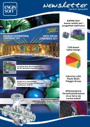
PAGE 17 PARAMETRIC<br />
FEM MODEL OPTIMIZATION FOR<br />
A PYROLITIC INDESIT OVEN<br />
PAGE 21 OPTIMIZATION<br />
OF A BUMPER<br />
SYSTEM AT VOLVO CARS<br />
PAGE 32 AERONAUTICAL<br />
ENGINES: REDUCTION<br />
OF EMISSIONS AND<br />
CONSUMPTIONS WITH<br />
A PROCESS SIMULATION<br />
STUDY<br />
Newsletter <strong>EnginSoft</strong><br />
Year 6 n°4 - Winter 2009<br />
If you want to receive a free copy of the next Enginsoft<br />
Newsletters, please contact our Marketing office at:<br />
newsletter@enginsoft.it<br />
All pictures are protected by copyright. Any reproduction<br />
of these pictures in any me<strong>di</strong>a and by any means is forbidden<br />
unless written authorization by Enginsoft.<br />
©Copyright <strong>EnginSoft</strong> Newsletter.<br />
Advertisement<br />
If you want to purchase advertising spaces within our<br />
newsletter, please contact the Marketing office at: Luisa<br />
Cunico - newsletter@enginsoft.it<br />
<strong>EnginSoft</strong> S.p.A.<br />
24124 BERGAMO Via Galimberti, 8/D<br />
Tel. +39 035 368711 • Fax +39 0461 979215<br />
50127 FIRENZE Via Panciatichi, 40<br />
Tel. +39 055 4376113 • Fax +39 055 4223544<br />
35129 PADOVA Via Giambellino, 7<br />
Tel. +39 49 7705311 • Fax 39 049 7705333<br />
72023 MESAGNE (BRINDISI) Via A. Murri, 2 - Z.I.<br />
Tel. +39 0831 730194 • Fax +39 0831 730194<br />
38123 TRENTO fraz. Mattarello - via della Stazione, 27<br />
Tel. +39 0461 915391 • Fax +39 0461 979201<br />
www.enginsoft.it - www.enginsoft.com<br />
e-mail: info@enginsoft.it<br />
COMPANY INTERESTS<br />
ESTECO <strong>EnginSoft</strong> Tecnologie per l’Ottimizzazione<br />
34016 TRIESTE Area Science Park • Padriciano 99<br />
Tel. +39 040 3755548 • Fax +39 040 3755549<br />
www.esteco.com<br />
CONSORZIO TCN<br />
38123 TRENTO Via della Stazione, 27 - fraz. Mattarello<br />
Tel. +39 0461 915391 • Fax +39 0461 979201<br />
www.consorziotcn.it<br />
<strong>EnginSoft</strong> GmbH - Germany<br />
<strong>EnginSoft</strong> UK - United Kingdom<br />
<strong>EnginSoft</strong> France - France<br />
<strong>EnginSoft</strong> Nor<strong>di</strong>c - Sweden<br />
Aperio Tecnologia en Ingenieria - Spain<br />
www.enginsoft.com<br />
ASSOCIATION INTERESTS<br />
NAFEMS International<br />
www.nafems.it<br />
www.nafems.org<br />
TechNet Alliance<br />
www.technet-alliance.com<br />
RESPONSIBLE DIRECTOR<br />
Stefano Odorizzi - newsletter@enginsoft.it<br />
ART DIRECTOR<br />
Luisa Cunico - newsletter@enginsoft.it<br />
PRINTING<br />
Grafiche Dal Piaz - Trento<br />
Newsletter <strong>EnginSoft</strong> Year 6 n°4 - 5<br />
The <strong>EnginSoft</strong> NEWSLETTER is a quarterly<br />
magazine published by <strong>EnginSoft</strong> SpA<br />
Autorizzazione del Tribunale <strong>di</strong> Trento n° 1353 RS <strong>di</strong> data 2/4/2008
6 - Newsletter <strong>EnginSoft</strong> Year 6 n°4<br />
modeFRONTIER:<br />
release 4.1.2 highlights<br />
ESTECO is proud to announce the release of v4.1 of the<br />
multi-objective optimization and design environment<br />
<strong>software</strong>, modeFRONTIER. This state of-the-art PIDO tool,<br />
written to allow easy coupling to almost any Computer-<br />
Aided-Engineering (CAE) tool, is now even more powerful<br />
and user-friendly than previous versions.<br />
DOE Algorithms<br />
New features have been added to the list of available<br />
algorithms in the DOE Sequence:<br />
Incremental Space Filler<br />
Inscribed Composite Design<br />
Uniform Reducer<br />
Dataset Reducer<br />
Schedulers and Optimizers<br />
New features have been added to the list of algorithms<br />
available in the Scheduler and Optimizers:<br />
Polynomial Chaos<br />
Evolution Strategy<br />
Lipschitz Sampling<br />
Mixed Integer Programming Sequential Quadratic<br />
Programming<br />
Response Surface Algorithms<br />
Evolutionary Design is now available, which implements a<br />
symbolic regression technique based on GP (Genetic<br />
Programming). The algorithm searches for the analytical<br />
expressions that are able to approximate the <strong>training</strong> data<br />
set. The users select the operators to be used among the<br />
basic mathematical functions (+,-,*,/,cos(),sin(),tg(),exp(),<br />
etc.) and the program evaluates the analytical expression.<br />
Data Mining<br />
New functions have been added to the Tools and Charts<br />
available in order to make life easier for users when exploring<br />
and assessing the data available in the Design Space tables:<br />
Auto-Report<br />
publishing results is just a few clicks away, thus the users can<br />
create automatic/custom report accor<strong>di</strong>ng to their needs.<br />
Principal Component Analysis and Multi-Dimensional<br />
Scaling<br />
Principal Component Analysis, designed to extract the<br />
significant latent variables out of a multi-<strong>di</strong>mension set of<br />
data and Multi-Dimensional Scaling, a powerful tool for<br />
exploring and analyzing sets of data have been added to the<br />
Multi-Variate Analysis Tool.<br />
Distribution Fitting<br />
Distribution Fitting chart has been designed for fitting<br />
univariate <strong>di</strong>stributions to sets of existing data<br />
Multi-Vector<br />
Multi-Vector chart lets the users <strong>di</strong>splay vector data in a<br />
single plot<br />
The Workflow<br />
New features have been added to the list of CAD/CAE Nodes<br />
available in the Workflow library<br />
Flowmaster V7<br />
LMS Virtual.Lab<br />
ANSA<br />
Design Target Node<br />
It is now possible to easily assign an external vector as<br />
target function, by importing from an external text file or<br />
pasting the data values from the clipboard. This feature,<br />
coupled with the Levenberg-Marquardt algorithm is ideally<br />
suited for most of the common curve-fitting design problems.<br />
For further information:<br />
Ing. Francesco Franchini - info@enginsoft.it<br />
Moldflow MPI<br />
GT-SUITE<br />
MSC Adams/View
Newsletter <strong>EnginSoft</strong> Year 6 n°4 - 7<br />
MAGMA 5: le nuove frontiere della<br />
simulazione <strong>di</strong> processo<br />
Con il mese <strong>di</strong> Novembre 2009 è iniziata la consegna della<br />
versione 5.0 <strong>di</strong> MAGMASOFT, denominata MAGMA5, che copre<br />
i principali aspetti dei processi <strong>di</strong> colata in SABBIA per<br />
leghe ferrose e non ferrose.<br />
MAGMA5 è molto più <strong>di</strong> una semplice nuova release: è un<br />
ambiente totalmente nuovo, basato sulle più recenti tecnologie<br />
<strong>software</strong>, che rivoluzionerà l'utilizzo della simulazione.<br />
Con questo nuovo strumento <strong>di</strong>venta molto più semplice<br />
creare e gestire i modelli, impostare la simulazione e visualizzare<br />
in maniera efficiente i risultati.<br />
Fig.1: Esempi delle <strong>di</strong>verse modalità <strong>di</strong> visualizzazione dell’ambiente CAD<br />
Il nuovo ambiente CAD per la modellazione solida si interfaccia<br />
con gli altri CAD commerciali, offrendo la possibilità<br />
<strong>di</strong> importare ed esportare file geometrici <strong>di</strong> vari formati: all’interfaccia<br />
STL si potrà affiancare il formato STEP per un<br />
periodo <strong>di</strong> prova <strong>di</strong> un anno senza costi aggiuntivi, mentre<br />
<strong>di</strong>ventano <strong>di</strong>sponibili come opzioni attivabili anche le interfacce<br />
CATIA V5 (solo per le piattaforme Windows) e Pro/E.<br />
La manipolazione e la visualizzazione dei modelli geometrici<br />
cambia ra<strong>di</strong>calmente: l’utente può scegliere <strong>di</strong><br />
lavorare con più quadranti attivi fino ad un massimo <strong>di</strong><br />
9; i quattro classici quadranti del preprocessore <strong>di</strong><br />
MAGMASOFT rimangono come una delle possibili soluzioni<br />
predefinite, anche se l’utilizzatore troverà molto<br />
comodo e intuitivo <strong>di</strong>segnare visualizzando il modello<br />
in un’unica finestra, dove i coman<strong>di</strong> <strong>di</strong> rotazione, traslazione,<br />
zoom e clipping sono utilizzabili in modo <strong>di</strong>namico<br />
e interattivo come nell’attuale post-processore<br />
(fig1).<br />
L’albero delle geometrie, <strong>di</strong>sponibile a sinistra dell’ambiente<br />
CAD, restituisce con imme<strong>di</strong>atezza la visualizzazione<br />
dei volumi creati o importati. Operazioni quali la<br />
mo<strong>di</strong>fica delle grandezze geometriche o dell’or<strong>di</strong>ne dei<br />
volumi, la selezione, il copia e incolla <strong>di</strong> geometrie esistenti<br />
sono rese semplici e veloci attraverso l’utilizzo del solo<br />
mouse.<br />
Il nuovo comando “copy with reference” <strong>di</strong> volumi creati all’interno<br />
<strong>di</strong> MAGMA5 lega le copie al volume originario, in<br />
modo che ogni mo<strong>di</strong>fica effettuata su quest’ultimo sia automaticamente<br />
applicata a tutte.<br />
Nuove funzioni CAD sono state implementate per offrire la<br />
possibilità <strong>di</strong> modellare più velocemente e in modo flessibile<br />
modelli complessi: geometrie estruse con sezione termi-<br />
nale <strong>di</strong> forma <strong>di</strong>fferente rispetto a quella iniziale sono facilmente<br />
ottenibili con il nuovo comando skin (fig2).<br />
Inoltre, tutti i soli<strong>di</strong> possono essere dotati <strong>di</strong> raggi <strong>di</strong> raccordo<br />
semplicemente prevedendoli nel momento in cui si <strong>di</strong>segna<br />
la sezione. Per esempio, attraverso la finestra <strong>di</strong> controllo,<br />
è possibile impostare le grandezze caratteristiche <strong>di</strong><br />
una sezione trapezoidale: altezza, <strong>di</strong>mensione della base<br />
Fig.2: Il comando skin permette <strong>di</strong> estrudere volumi con sezione finale <strong>di</strong> forma<br />
<strong>di</strong>versa da quella iniziale
8 - Newsletter <strong>EnginSoft</strong> Year 6 n°4<br />
Fig.3: Esempio <strong>di</strong> impostazione <strong>di</strong> un raggio <strong>di</strong> raccordo<br />
Fig.4: Generazione <strong>di</strong> anime attraverso l’utilizzo <strong>di</strong> operazioni booleane<br />
(maggiore e/o minore) e angolo <strong>di</strong> sformo sono completati<br />
dall’opzione del raggio <strong>di</strong> raccordo (fig.3).<br />
Operazioni booleane sono permesse tra modelli importati da<br />
CAD esterni e geometrie create all’interno <strong>di</strong> MAGMA5. Un<br />
esempio classico è costituito dalla generazione <strong>di</strong> anime <strong>di</strong><br />
forma complessa con le relative portate (fig.4).<br />
Al termine della progettazione, il modello CAD deve essere<br />
tradotto attraverso l’utilizzo della mesh in modello matematico.<br />
Dalla qualità della mesh <strong>di</strong>pende l’accuratezza dei risultati<br />
e il corrispondente tempo <strong>di</strong> calcolo. MAGMA5 offre<br />
la possibilità <strong>di</strong> caratterizzare i volumi necessari<br />
alla simulazione, attraverso la generazione<br />
del modello <strong>di</strong>scretizzato, in un numero <strong>di</strong><br />
livelli <strong>di</strong> affinazione scelto dall’utente<br />
(fig.5), con il vantaggio <strong>di</strong> non rinunciare alla<br />
qualità (visualizzandola istantaneamente<br />
al termine della generazione) e <strong>di</strong> minimizzare<br />
i tempi <strong>di</strong> calcolo.<br />
Sui domini riconosciuti dalla mesh vengono<br />
risolte le equazioni relative alla fluido<strong>di</strong>namica,<br />
alla termica e alle tensioni residue. I corrispettivi<br />
solutori <strong>di</strong> calcolo sono arricchiti <strong>di</strong><br />
ulteriori modelli computazionali, come per<br />
esempio un nuovo modello <strong>di</strong> turbolenza per<br />
la simulazione del riempimento della cavità<br />
che considera l’effetto della tensione superfi-<br />
Fig.5: Pannello <strong>di</strong> generazione della mesh<br />
ciale, mentre un nuovo modello <strong>di</strong> plasticità viene<br />
implementato per un calcolo delle tensioni residue<br />
più accurato, con la possibilità <strong>di</strong> includere<br />
l’effetto del contatto del pezzo con le pareti<br />
della forma <strong>di</strong> sabbia o anima.<br />
A completamento della previsione della qualità<br />
del getto, è possibile simulare qualsiasi trattamento<br />
termico. Per esempio, considerando il<br />
classico trattamento T6, il modello <strong>di</strong> calcolo degli<br />
stress residui valuterà il rilassamento delle<br />
tensioni dopo colata durante la fase <strong>di</strong> solubilizzazione,<br />
l’insorgere <strong>di</strong> nuove eventuali tensioni<br />
residue durante la fase <strong>di</strong> tempra e il successivo<br />
stato <strong>di</strong> tensione generato dalla fase <strong>di</strong> invecchiamento.<br />
Dal momento che le operazioni meccaniche<br />
(come per es. la smaterozzatura) mutano<br />
ulteriormente la <strong>di</strong>stribuzione delle tensioni residue<br />
presenti a seguito della colata, MAGMA5 of-<br />
fre la possibilità <strong>di</strong> includerle nell’analisi <strong>di</strong> stress. La conoscenza<br />
delle tensioni residue permette al progettista <strong>di</strong> valutare<br />
più accuratamente la resistenza in esercizio <strong>di</strong> un<br />
componente e qualora fosse <strong>di</strong> interesse, attraverso l’utilizzo<br />
<strong>di</strong> MAGMAlink, <strong>di</strong> utilizzare la loro <strong>di</strong>stribuzione come<br />
stato iniziale in una simulazione strutturale.<br />
L'impostazione del processo <strong>di</strong> simulazione può ora essere<br />
elaborato in finestre parallele agli ambiente CAD, mesh e<br />
postprocessore. Nella finestra principale coesistono, infatti,<br />
<strong>di</strong>versi menù a ten<strong>di</strong>na nei quali è possibile entrare con un<br />
semplice “clic” per poter creare la geometria (fig.6a), visua-
Fig.6: Pannello <strong>di</strong> gestione: a) ambiente CAD,b) visualizzatore della mesh,c) settaggio della simulazione.<br />
Fig.7: Previsione della qualità del getto attraverso la visualizzazione <strong>di</strong><br />
<strong>di</strong>fferenti risultati contemporaneamente.<br />
lizzare la mesh, definire i parametri <strong>di</strong> processo (fig.6b) e<br />
analizzare i risultati (fig.7.). Il veloce passaggio da una finestra<br />
all’altra comporta un notevole miglioramento nei<br />
tempi <strong>di</strong> impostazione della simulazione.<br />
L’analisi dei risultati viene agevolata dalla visualizzazione <strong>di</strong><br />
più finestre contemporaneamente, in ognuna delle quali è<br />
possibile analizzare un risultato <strong>di</strong>verso e usufruire dei classici<br />
coman<strong>di</strong> <strong>di</strong> rotazione <strong>di</strong>namica, traslazione, sezione e<br />
animazione (fig.7).<br />
L’innovativo comando “picking” permette <strong>di</strong> rilevare il valore<br />
puntuale <strong>di</strong> qualsiasi risultato con un semplice “clic” nella<br />
zona <strong>di</strong> interesse. Una finestra informativa restituisce le<br />
coor<strong>di</strong>nate del punto selezionato e<br />
il corrispondente valore. Inoltre è<br />
possibile salvare in formato grafico<br />
l’evoluzione dei valori dei risultati<br />
fluido<strong>di</strong>namici e termici dei punti<br />
selezionati per l’intero arco <strong>di</strong> tempo<br />
simulato (fig.8).<br />
I settaggi, pre<strong>di</strong>sposti dall’utente<br />
(viste, sezioni, scale e risultati), per<br />
il salvataggio delle immagini dei risultati<br />
vengono memorizzati nel file<br />
MAGMASOFT.pdb che consente <strong>di</strong> richiamare<br />
le stesse impostazioni anche<br />
per le versioni successive, agevolando<br />
l’analisi <strong>di</strong> confronto <strong>di</strong> <strong>di</strong>-<br />
Newsletter <strong>EnginSoft</strong> Year 6 n°4 - 9<br />
verse simulazioni e <strong>di</strong> salvare le<br />
immagini in background.<br />
La nuova modalità <strong>di</strong> visualizzazione<br />
e i nuovi criteri (microporosità<br />
e proprietà meccaniche) del<br />
modulo opzionale Non-ferrous<br />
permettono meto<strong>di</strong> <strong>di</strong> verifica<br />
delle prestazioni del getto più efficienti<br />
e imme<strong>di</strong>ati.<br />
Tale modulo restituisce, per le leghe<br />
<strong>di</strong> alluminio, la previsione<br />
della microstruttura e delle proprietà<br />
meccaniche allo stato “as<br />
cast”, calcolate sulla base della composizione chimica della<br />
lega, della velocità <strong>di</strong> raffreddamento del sistema e dei trattamenti<br />
della lega eseguiti prima della colata (es degasaggio).<br />
I moduli MAGMAhpdc, MAGMAlpdc e MAGMAPermanent<br />
mold, oltre MAGMAlink e MAGMA<strong>di</strong>sa, sono in fase <strong>di</strong> completamento<br />
e verranno rilasciati con la versione 5.1, mentre<br />
MAGMAfrontier con la successiva 5.2.<br />
Nel periodo <strong>di</strong> transizione, MAGMA4.4. e MAGMA5 potranno<br />
coesistere sullo stesso hardware, a con<strong>di</strong>zione che il sistema<br />
operativo sia supportato per entrambe le versioni.<br />
MAGMA5 è stato sviluppato in linguaggio JAVA per sfruttare<br />
al meglio le potenzialità <strong>di</strong> Windows 64 bit, mentre rimangono<br />
supportate le piattaforme LINUX RedHat5 e SU-<br />
SE11 a 64 bit.<br />
Per prendere visione degli hardware suggeriti e delle piattaforme<br />
supportate dal nuovo <strong>software</strong> visitate la pagina:<br />
http://www.enginsoft.it/<strong>software</strong>/magmasoft/news/<br />
magma5.html<br />
Le date dei <strong>corsi</strong> <strong>di</strong> formazione sono come <strong>di</strong> consueto pubblicate<br />
alla pagina:<br />
http://www.enginsoft.it/formazione/<strong>corsi</strong><strong>2010</strong>/<br />
processo/proc14.html<br />
Per maggiori informazioni:<br />
Ing. Nicola Gramegna - info@enginsoft.it<br />
Fig.8: Visualizzazione <strong>di</strong> valori puntuali e della corrispondente curva temperatura-tempo
10 - Newsletter <strong>EnginSoft</strong> Year 6 n°4<br />
FORGE 2009<br />
Release notes - <strong>di</strong>cembre 2009<br />
Nel mese <strong>di</strong> <strong>di</strong>cembre 2009 è stato rilasciato da Transvalor il<br />
nuovo pacchetto <strong>di</strong> simulazione Forge 2009®, lo strumento<br />
ideale per la simulazione dell’intero processo <strong>di</strong> stampaggio<br />
a caldo o a freddo dei più svariati componenti (alberi, giunti,<br />
ingranaggi, flange, raccor<strong>di</strong>, cuscinetti, bulloni, viti, fasteners,<br />
…). È possibile simulare la sequenza completa <strong>di</strong> un<br />
processo <strong>di</strong> forgiatura multista<strong>di</strong>o con una cinematica degli<br />
stampi anche molto complessa (stampi flottanti o pre-caricati),<br />
seguita da raffreddamenti, tranciatura bave e/o trattamenti<br />
termici.<br />
Forge 2009® è la logica evoluzione <strong>di</strong> Forge2008® ed è un<br />
<strong>software</strong> <strong>di</strong> simulazione FEM de<strong>di</strong>cato alla simulazione <strong>di</strong> processi<br />
assialsimmetrici (2D) e <strong>di</strong> qualsivoglia geometria (3D),<br />
che è stato sviluppato seguendo le in<strong>di</strong>cazioni degli utilizzatori.<br />
Forge 2009 – ottimizzazione dei processi <strong>di</strong> forgiatura<br />
La principale novità introdotta nella nuova release è la possibilità<br />
<strong>di</strong> effettuare una procedura automatica <strong>di</strong> ottimizzazione<br />
per un determinato progetto in una o più operazioni.<br />
Già nelle versioni precedenti era stato introdotto il concetto<br />
<strong>di</strong> “chaining”, che<br />
consentiva <strong>di</strong> impostare<br />
una intera sequenza<br />
<strong>di</strong> stampaggio<br />
e concatenare le singole<br />
operazioni in un<br />
unico calcolo, trasferendo<br />
in automatico i<br />
risultati tra le stazioni.<br />
Oggi è possibile<br />
definire delle variabili<br />
in ingresso sulla prima<br />
operazione, come<br />
ad esempio le <strong>di</strong>mensioni<br />
caratteristiche<br />
della billetta o altri<br />
parametri quali per esempio la corsa della pressa, chiedendo<br />
al <strong>software</strong> <strong>di</strong> ricavare i migliori risultati per degli obiettivi<br />
definiti dall’utente, come per esempio il migliore riempimento<br />
delle impronte nell’ultima operazione o la richiesta<br />
<strong>di</strong> un pezzo privo <strong>di</strong> ripieghe o ancora la<br />
minimizzazione del carico pressa. Il modulo <strong>di</strong> ottimizzazione<br />
effettua una serie <strong>di</strong> “run”, valutandone<br />
i risultati e mo<strong>di</strong>ficando le variabili in ingresso,<br />
in modo da ottenere i migliori risultati<br />
possibili. Le varie configurazioni sono classificate<br />
in funzione della combinazione <strong>di</strong> obiettivi raggiunti,<br />
consentendo <strong>di</strong> in<strong>di</strong>viduare le configurazioni<br />
migliori.<br />
Interfaccia <strong>di</strong> ottimizzazione<br />
Il progettista, che in precedenza testava con Forge solo un<br />
numero limitato <strong>di</strong> ipotesi, può limitarsi ora a definire, me<strong>di</strong>ante<br />
una interfaccia user-friendly, le variabili, i vincoli del<br />
processo e gli obiettivi da raggiungere, lasciando a Forge il<br />
compito <strong>di</strong> esplorare un numero decisamente maggiore <strong>di</strong><br />
configurazioni: le migliori possono essere magari ipotesi che<br />
il progettista non avrebbe considerato. Grazie all’esperienza<br />
maturata utilizzando questo strumento, Transvalor, l’azienda<br />
che sviluppa il <strong>software</strong>,<br />
intende aggiungere<br />
altre variabili ed obiettivi<br />
che possono essere<br />
gestiti dall’utente nelle versioni successive.<br />
In caso fosse necessario utilizzare uno strumento più flessibile<br />
ed in grado <strong>di</strong> consentire un’analisi più accurata dei risultati,<br />
è possibile interfacciare il <strong>software</strong> con il <strong>software</strong><br />
modeFRONTIER prodotto da ESTECO e <strong>di</strong>stribuito da<br />
<strong>EnginSoft</strong>; è possibile in questo caso sfruttare i no<strong>di</strong> <strong>di</strong>retti<br />
verso i principali CAD e mo<strong>di</strong>ficare le geometrie <strong>di</strong> pezzo o<br />
stampi, importandole quin<strong>di</strong> in Forge, per lanciare poi il calcolo<br />
ed utilizzare gli strumenti avanzati del programma per<br />
l’analisi degli obiettivi.<br />
Il processo <strong>di</strong> laminazione circolare – ring rolling<br />
L’esperienza accumulata grazie ai <strong>di</strong>versi utilizzatori del <strong>software</strong><br />
per il processo <strong>di</strong> ring-rolling ha consentito a Transvalor<br />
<strong>di</strong> introdurre una serie <strong>di</strong> migliorie al modello utilizzato, che<br />
hanno portato ad un deciso miglioramento della qualità dei<br />
risultati, con una riduzione dei tempi <strong>di</strong> calcolo nell’or<strong>di</strong>ne<br />
del 30% rispetto alla versione precedente. Tra le novità più<br />
significative, la possibilità <strong>di</strong> inserire la curva <strong>di</strong> laminazione<br />
che normalmente viene impostata dall’operatore del laminatoio,<br />
ed ottenere in automatico le curve <strong>di</strong> movimento <strong>di</strong> coni<br />
e mandrino per Forge. Per il mandrino, la velocità può anche<br />
essere modulata in funzione della crescita del <strong>di</strong>ametro<br />
esterno dell’anello. Il nuovo modello consente ora anche <strong>di</strong><br />
rilevare la velocità <strong>di</strong> rotazione del mandrino folle per effetto<br />
del contatto con il pezzo.<br />
Molto lavoro è stato de<strong>di</strong>cato al miglioramento delle routine<br />
<strong>di</strong> calcolo: i nuovi algoritmi PETSC consentono <strong>di</strong> risolvere<br />
profili anche molto complessi in tempi<br />
molto inferiori ai precedenti, con una<br />
precisione <strong>di</strong> risultati decisamente<br />
maggiore grazie all’introduzione <strong>di</strong> nuove<br />
funzioni <strong>di</strong> contatto.<br />
Simulazione processo <strong>di</strong> Ring-rolling<br />
Il processo <strong>di</strong> fucinatura –<br />
nuovi strumenti <strong>di</strong>sponibili<br />
Il processo <strong>di</strong> forgiatura/fucinatura è<br />
caratterizzato da un numero molto ele-
vato <strong>di</strong> passate, ognuna con <strong>di</strong>versi colpi ed una movimentazione<br />
del pezzo anche complessa con dei tempi <strong>di</strong> attesa tra<br />
ogni colpo/passata. Il modello precedente, presente in<br />
Forge2008, è stato ulteriormente arricchito <strong>di</strong> funzioni, tra le<br />
quali i tempi morti tra due colpi consecutivi, nel quali viene<br />
calcolato il raffreddamento del pezzo, l’arresto del calcolo<br />
una volta che il pezzo è uscito dagli stampi, una migliore gestione<br />
degli scorrimenti del pezzo rispetto agli stampi grazie<br />
all’uso <strong>di</strong> manipolatori. Dal punto <strong>di</strong> vista operativo, la miglioria<br />
principale è una mo<strong>di</strong>fica e semplificazione delle modalità<br />
<strong>di</strong> definizione delle passate, attraverso un nuovo formato<br />
<strong>di</strong> file generato in automatico dal programma.<br />
Le lavorazioni <strong>di</strong> fucinatura hanno l’obiettivo <strong>di</strong> chiudere le<br />
porosità, che sono causate dal processo <strong>di</strong> colata del lingotto<br />
e che hanno una notevole influenza sulla qualità del pezzo<br />
finito. Transvalor ha de<strong>di</strong>cato molte energie per implementare<br />
questo aspetto in Forge: è stata aggiunta la possibilità<br />
<strong>di</strong> definire sul lingotto una <strong>di</strong>stribuzione iniziale <strong>di</strong> porosità<br />
e tra i risultati la possibilità <strong>di</strong> visualizzare la chiusura<br />
<strong>di</strong> tali porosità. La <strong>di</strong>stribuzione iniziale <strong>di</strong> porosità può<br />
essere ottenuta anche me<strong>di</strong>ante l’uso <strong>di</strong> un altro <strong>software</strong> <strong>di</strong><br />
Transvalor, Thercast, de<strong>di</strong>cato alla simulazione del processo<br />
<strong>di</strong> colata e raffreddamento in lingottiera ed in grado <strong>di</strong> calcolare<br />
la formazione <strong>di</strong> porosità con il criterio <strong>di</strong> Yamanaka.<br />
I risultati calcolati da Thercast possono essere trasferiti <strong>di</strong>rettamente<br />
in Forge, per ottenere una <strong>di</strong>stribuzione molto<br />
realistica delle porosità nel lingotto iniziale.<br />
Calcolo delle porosità in Thercast e trasferimento in Forge<br />
Altro aspetto fondamentale in questo tipo <strong>di</strong> processi è l’evoluzione<br />
del grano cristallino funzione della ricristallizzazione.<br />
Forge da questa versione è in grado <strong>di</strong> seguire l’evoluzione<br />
del grano cristallino per effetto della ricristallizzazione statica<br />
e <strong>di</strong>namica, basandosi sulle definizioni dei materiali provenienti<br />
da prove sperimentali e dal <strong>software</strong> JmatPro: sono<br />
<strong>di</strong>sponibili i dati <strong>di</strong> alcune leghe molto particolari e critiche<br />
per questi aspetti, quali: acciaio AISI316L, Inconel 718,<br />
Waspalloy ed alcuni acciai al manganese.<br />
Stampaggio lamiere - anisotropia<br />
Nel campo dello stampaggio ed imbutitura delle lamiere gli<br />
effetti legati all’anisotropia del materiale sono rilevanti.<br />
Newsletter <strong>EnginSoft</strong> Year 6 n°4 - 11<br />
Nella nuova versione <strong>di</strong> Forge è stato introdotto un nuovo<br />
modello <strong>di</strong> materiale nel quale è possibile specificare i parametri<br />
<strong>di</strong> anisotropia secondo il modello <strong>di</strong> Hill. Il solutore è<br />
stato quin<strong>di</strong> adeguato per tener conto <strong>di</strong> questa nuova definizione<br />
e nel post-processore sono stati aggiunti dei risultati<br />
in grado <strong>di</strong> consentire una migliore comprensione <strong>di</strong> questi<br />
effetti<br />
Contatto materiale-materiale e ripieghe<br />
Grazie alle esperienze provenienti dagli utilizzatori, soprattutto<br />
nel campo dello stampaggio dei materiali non ferrosi<br />
(ottone ed alluminio), si è evidenziata la necessità <strong>di</strong> ripensare<br />
il modo nel quale il <strong>software</strong> evidenzia la formazione e<br />
l’evoluzione delle ripieghe. Sono state quin<strong>di</strong> messe a punto<br />
delle nuove funzioni <strong>di</strong> contatto in grado <strong>di</strong> gestire in maniera<br />
più efficiente le situazioni, ove il materiale ripiega su se<br />
stesso. Contemporaneamente è stato sviluppato un nuovo<br />
approccio per la visualizzazione dei <strong>di</strong>fetti nel post-processore:<br />
quando due lembi <strong>di</strong> materiale vengono in contatto tra loro,<br />
si genera un tracciante, il cui movimento nel resto della<br />
corsa <strong>di</strong> stampaggio consente <strong>di</strong> valutare con una notevole<br />
precisione forma e <strong>di</strong>mensioni delle ripieghe. Oltre alla localizzazione<br />
delle ripieghe, che era già presente nella precedente<br />
versione, il progettista è in grado <strong>di</strong> comprendere se, effettivamente,<br />
il <strong>di</strong>fetto interessa<br />
il pezzo e per che spessore<br />
o se esce verso le bave e<br />
quin<strong>di</strong> non è critico per la qualità<br />
del pezzo. Effetti indotti<br />
<strong>di</strong> questi miglioramenti al motore<br />
<strong>di</strong> calcolo sono stati una<br />
riduzione dei tempi <strong>di</strong> calcolo<br />
stimabile me<strong>di</strong>amente dal 20%<br />
al 30% a seconda del numero<br />
<strong>di</strong> no<strong>di</strong> utilizzato e del tipo <strong>di</strong><br />
calcolo impostati, miglioramento<br />
riscontrato sia sulle configurazioni singolo processore,<br />
che sulle più potenti piattaforme cluster.<br />
Tracciatura delle ripieghe<br />
Un nuovo “wizard” per lo stampaggio a freddo<br />
Nella versione 2008 è stato introdotto il concetto <strong>di</strong> “wizard”,<br />
uno strumento in grado <strong>di</strong> guidare passo-passo l’utente<br />
nella creazione della singola operazione, utile soprattutto<br />
per i neofiti, che possono creare con pochi parametri un progetto<br />
pronto per essere risolto. Nella versione 2009 è stato<br />
aggiunto un wizard per lo stampaggio a freddo.<br />
Molte le migliorie introdotte nel pre- e nel<br />
post-processing<br />
Per Transvalor le linee <strong>di</strong> sviluppo del <strong>software</strong> sono sempre<br />
guidate dai suggerimenti degli utenti. Nella nuova versione<br />
<strong>di</strong>verse sono le migliorie apportate, che riassumiamo <strong>di</strong> seguito.<br />
1. Pre-processore e template <strong>di</strong> processo<br />
Diverse migliorie minori molto utili sono state introdotte nelle<br />
finestre <strong>di</strong> impostazione dei progetti. Nel pre-processore
12 - Newsletter <strong>EnginSoft</strong> Year 6 n°4<br />
l’attenzione si è concentrata, in particolar modo, sul miglioramento<br />
<strong>di</strong> alcuni template <strong>di</strong> processo, i modelli che servono<br />
da base per l’impostazione <strong>di</strong> tipologie particolari <strong>di</strong> calcolo.<br />
Per quanto riguarda il modello delle presse ad energia, pressa<br />
a vite e maglio, è stato riformulato invece il modello in<br />
grado <strong>di</strong> tener conto dell’efficienza della macchina al procedere<br />
dei numero <strong>di</strong> colpi ed è stata aggiunta la possibilità <strong>di</strong><br />
inserire un tempo <strong>di</strong> pausa prima dell’inizio dello stampaggio,<br />
con il risultato che ora le temperature del pezzo all’inizio<br />
del processo sono molto più precise.<br />
Per quanto riguarda lo stampaggio <strong>di</strong> ottone, nelle configurazioni<br />
<strong>di</strong> stampaggio a forare, ora è possibile introdurre carrelli<br />
inclinati, seguire lo stampaggio <strong>di</strong> più particolari (multi<br />
impronta), valutare con precisione i carichi su ogni punzone<br />
in funzione della resistenza del cuscino. Sono in corso mo<strong>di</strong>fiche<br />
ancora più rilevanti per questo modello, con la possibilità<br />
<strong>di</strong> gestire configurazioni a forare più complesse o a cam-<br />
Stampaggio ottone con carrelli inclinati Bigorniatura anello in acciaio<br />
pana. Sempre in tema <strong>di</strong> cinematiche molto complesse, sono<br />
stati messi a punto nuovi modelli <strong>di</strong> stampi flottanti in traslazione<br />
e rotazione, ma anche <strong>di</strong> stampi “slave” sia in traslazione,<br />
che in rotazione, collegabili al movimento <strong>di</strong> altri<br />
stampi “master”.<br />
Per quanto riguarda la laminazione, sono stati sviluppati nuovi<br />
strumenti in grado <strong>di</strong> creare, per rivoluzione, il profilo dei<br />
rulli a partire da un profilo 2D, la cui forma può essere mo<strong>di</strong>ficata<br />
<strong>di</strong>rettamente nel pre-processor, muovendo o trascinando<br />
in no<strong>di</strong> del profilo.<br />
Parlando poi delle funzioni comuni a tutti i progetti, è proseguito<br />
il miglioramento delle funzioni <strong>di</strong> meshatura da geometrie<br />
STL, con una qualità decisamente superiore rispetto<br />
alle versioni precedenti.<br />
2. Solutore<br />
L’evoluzione della parte del <strong>software</strong> relativa al calcolo ha seguito<br />
due filoni principali. Le routine <strong>di</strong> calcolo sono state<br />
sensibilmente migliorate, ottenendo una migliore qualità della<br />
mesh, in grado <strong>di</strong> rispettare meglio la forma degli stampi,<br />
una maggiore stabilità del solutore soprattutto per configurazioni<br />
multi-processore e/o multi-core e, <strong>di</strong> conseguenza,<br />
tempi <strong>di</strong> calcolo significativamente minori (-20-30% a seconda<br />
dei casi) rispetto alla versione precedente. Il solutore è<br />
stato inoltre mo<strong>di</strong>ficato per tener conto degli effetti <strong>di</strong> ani-<br />
sotropia del materiale e tutta una serie <strong>di</strong> nuove opzioni impostabili<br />
nei modelli de<strong>di</strong>cati ai singoli campi <strong>di</strong> applicazione:<br />
per esempio i raffreddamenti prima dello stampaggio nel<br />
modello della pressa a vite, nuove funzioni PETSC per la laminazione<br />
circolare, nuove funzioni per il tracciamento delle<br />
ripieghe. Per quanto riguarda il secondo aspetto, l’interfaccia<br />
per il lancio dei calcoli è stata ulteriormente evoluta e si presenta<br />
ora con delle nuove funzioni e scorciatoie per le operazioni<br />
più comuni.<br />
3. Post-processore<br />
Lo sviluppo del post-processore, funzione delle richieste degli<br />
utilizzatori, ha riguardato <strong>di</strong>versi aspetti. Tra i più utili in<br />
evidenza la creazione <strong>di</strong> un cubo <strong>di</strong> navigazione, che rende<br />
imme<strong>di</strong>ata la rotazione del modello nelle viste ortogonali agli<br />
assi principali. Sempre nella <strong>di</strong>rezione <strong>di</strong> una migliore gestione<br />
del punto <strong>di</strong> vista scelto, è stata implementata la possibilità<br />
<strong>di</strong> salvare il “workspace”: l’utente carica i risultati <strong>di</strong><br />
interesse (scalari, vettoriali, plot) anche<br />
per più progetti da confrontare,<br />
sceglie il punto <strong>di</strong> vista e le opzioni<br />
grafiche, carica eventuali animazioni e<br />
salva il “workspace”. Caricando questo<br />
file, vengono quin<strong>di</strong> ripristinate tutte<br />
le scelte dell’utente, opzione che consente<br />
un notevole risparmio <strong>di</strong> tempo<br />
nella fase <strong>di</strong> analisi dei risultati.<br />
La vista dei soli risultati in superficie<br />
non consente una valutazione <strong>di</strong> quanto<br />
realmente succede all’interno del<br />
pezzo: per questo scopo si utilizzano<br />
dei piani <strong>di</strong> sezione. Tra le nuove funzionalità<br />
introdotte per questo strumento, le più significative<br />
sono la possibilità <strong>di</strong> muovere il piano attorno ad un asse,<br />
la possibilità <strong>di</strong> selezionare dei punti sul piano, rilevandone<br />
i valori calcolati, e la possibilità <strong>di</strong> ottenere un grafico<br />
dell’area del piano in funzione della corsa impostata. Sempre<br />
per questo strumento risulta utile la possibilità <strong>di</strong> esportare<br />
il profilo del piano in formato dxf ed in coor<strong>di</strong>nate XY, che<br />
può quin<strong>di</strong> essere utilizzato in qualsiasi CAD, ma anche la<br />
possibilità <strong>di</strong> salvare, in un determinato istante della corsa,<br />
una animazione che mostri il piano <strong>di</strong> taglio che scorre attraverso<br />
il pezzo in una determinata <strong>di</strong>rezione, o secondo una<br />
rotazione attorno ad un asse. È così possibile valutare in una<br />
unica animazione cosa accade nelle varie sezioni del pezzo.<br />
Sempre in termini <strong>di</strong> strumenti <strong>di</strong> interfaccia con strumenti<br />
CAD o FEM, da ricordare<br />
la possibilità<br />
<strong>di</strong> esportare in<br />
formato .STL, scegliendo<br />
quali oggetti<br />
esportare e la<br />
possibilità <strong>di</strong> generare<br />
un file .UNV (Ideas<br />
universal file),<br />
che contiene sia la<br />
forma, ma anche<br />
Albero - Calcolo accoppiato tensione sugli stampi
tutti i risultati calcolati: è possibile quin<strong>di</strong> trasferire ad un<br />
altro strumento FEM quanto calcolato in Forge, per effettuare<br />
altri tipi <strong>di</strong> analisi, ad esempio del pezzo nelle con<strong>di</strong>zioni<br />
<strong>di</strong> carico corrispondenti alla sua messa in opera.<br />
Degno <strong>di</strong> nota è inoltre il miglioramento dell’interfaccia <strong>di</strong><br />
esportazione .vtf, che consente <strong>di</strong> esportare l’animazione <strong>di</strong><br />
un risultato in una forma ove l’utente ha la possibilità <strong>di</strong><br />
cambiare il punto <strong>di</strong> vista e/o lo zoom. Con il nuovo visualizzatore<br />
GlView Express, scaricabile gratuitamente, è ora<br />
possibile visualizzare nello stesso file più risultati, rendendo<br />
decisamente più agevole la comunicazione delle informazioni<br />
tra colleghi o verso l’esterno.<br />
Miglioramento continuo del database dei materiali<br />
Il database dei materiali è sempre stato uno dei punti car<strong>di</strong>ne<br />
<strong>di</strong> Forge, con le curve <strong>di</strong> deformazione a caldo ed a freddo,<br />
le caratteristiche elastiche e le proprietà termiche <strong>di</strong> oltre<br />
800 leghe ferrose e non ferrose. In questa versione sono<br />
stati aggiunti una serie<br />
<strong>di</strong> materiali provenienti<br />
dal programma<br />
JmatPro, quali acciai<br />
al Boro, micro legati,<br />
acciai inox, superleghe<br />
(inconel718, nimonic,<br />
waspalloy),<br />
leghe <strong>di</strong> Titanio, per i<br />
quali sono state calcolate<br />
le curve reologiche<br />
e le caratteristiche<br />
fisiche da temperatura<br />
ambiente alle<br />
temperature <strong>di</strong><br />
stampaggio a caldo.<br />
Da evidenziare come<br />
siano stati introdotti<br />
anche dei materiali<br />
che tengono conto<br />
dell’evoluzione del grano cristallino causato dalla ricristallizzazione<br />
e del kinematic hardening.<br />
Simulazione stampaggio a caldo fuso a snodo<br />
Simulazione laminazione <strong>di</strong> prodotti lunghi<br />
Installazione – versioni <strong>di</strong>sponibili<br />
Già nella versione precedente era possibile impostare una architettura<br />
client-server, concentrando le operazioni <strong>di</strong> calcolo<br />
sulla macchina più potente e demandando alle macchine<br />
client la preparazione dei calcoli e l’analisi dei risultati. Il sistema<br />
è stato ulteriormente evoluto, aggiungendo la possibilità<br />
<strong>di</strong> una licenza “floating”, che può essere attivata a turno<br />
su <strong>di</strong>verse macchine, aumentando la flessibilità <strong>di</strong> utilizzo<br />
in ambiente multiutente.La gamma <strong>di</strong> possibili installazioni<br />
<strong>di</strong> Forge è stata ampliata rispetto alla versione precedente.<br />
Oggi è possibile installare il <strong>software</strong> sia in sistema operativo<br />
a 32 o 64 bit Windows XP, Server® 2003, Server® 2008,<br />
VISTA business, Linux Red Hat Enterprise o SLES 10 64bits. In<br />
termini <strong>di</strong> piattaforme hardware, Forge sfrutta appieno la parallelizzazione<br />
del calcolo, quin<strong>di</strong> è possibile utilizzare una<br />
macchina con singolo processore 1-4core, con più processori<br />
Newsletter <strong>EnginSoft</strong> Year 6 n°4 - 13<br />
o sistemi cluster fino a 32 core, le cui code possono essere<br />
gestite anche me<strong>di</strong>ante i <strong>software</strong> pbs v5, pbs v9, lsf e sge.<br />
Gli ultimi benchmark effettuati su piattaforme equipaggiate<br />
con i nuovi processori Nehalem i7 (serie XEON 55**), con due<br />
processori 4core, hanno mostrato una notevole efficienza,<br />
con tempi <strong>di</strong> calcolo paragonabili a quelli prima ottenibili solo<br />
con un cluster, con una semplicità <strong>di</strong> gestione decisamente<br />
maggiore. Questo rende ora possibile lanciare anche su<br />
queste piattaforme analisi molto pesanti quali la laminazione<br />
<strong>di</strong> anelli, mesh molto fini o analisi con molti incrementi.<br />
Conclusioni<br />
Si può quin<strong>di</strong> affermare che Forge 2009® è un programma<br />
sempre in costante miglioramento, che ha raggiunto una notevole<br />
semplicità d’uso grazie all’esperienza<br />
accumulata con le versioni<br />
precedenti e i suggerimenti<br />
provenienti dagli utenti. Molte delle<br />
novità introdotte portano la versio-<br />
Stampaggio a freddo<br />
ne 2009 ad un livello <strong>di</strong><br />
precisione ed accuratezza<br />
decisamente superiore alla<br />
versione precedente.<br />
Dall’altra parte, la maturità<br />
raggiunta dal prodotto<br />
consente sempre un<br />
facile e rapido inserimento in qualsiasi ambiente tecnico, per<br />
la progettazione <strong>di</strong> prodotti ottenuti per stampaggio e l’ottimizzazione<br />
dei relativi processi produttivi. Con Forge 2009 è<br />
quin<strong>di</strong> possibile migliorare rapidamente la qualità dei pezzi,<br />
ridurre gli sprechi <strong>di</strong> materiale e aumentare la durata degli<br />
stampi e delle macchine <strong>di</strong> stampaggio. È possibile inoltre<br />
valutare in modo anticipato senza sorprese la stampabilità <strong>di</strong><br />
nuove forme o <strong>di</strong> materiali poco conosciuti.<br />
<strong>EnginSoft</strong>, <strong>di</strong>stributore in Italia del <strong>software</strong> Forge, grazie a<br />
tecnici specializzati con oltre 10 anni <strong>di</strong> esperienza, offre alle<br />
aziende del settore, formazione del personale ed avviamento<br />
all’uso oltre al supporto nell’installazione, nonché attività<br />
<strong>di</strong> simulazione su commessa, con impostazione del caso, analisi<br />
dei risultati e consulenza sull’ottimizzazione del processo.<br />
Rollatura del filetto<br />
Calcolo accoppiato vite,<br />
bullone e lamiera<br />
Per maggiori informazioni:<br />
Ing. Marcello Gabrielli - Responsabile <strong>di</strong> prodotto FORGE<br />
info@enginsoft.it
14 - Newsletter <strong>EnginSoft</strong> Year 6 n°4<br />
Elysium’s CADdoctor accelerating<br />
Reverse Engineering<br />
1. 3D data utilization in Reverse Engineering<br />
As the noncontact 3D measuring machine has become so<br />
popular, the <strong>di</strong>gitalization of physical models is needed more<br />
than ever. Tra<strong>di</strong>tionally, the main purpose of measuring physical<br />
models was ”Inspection” to determine if the products were<br />
manufactured following the original design by comparing CAD<br />
data and point cloud data measured by the contact measuring<br />
machine. However applications in “Reverse Engineering” have<br />
recently attracted a lot of attention. Typically, what we mean<br />
here is the way how to use CAD data produced from the huge<br />
Figure1: Deformation to the nearest point (solid arrow) and the ideal deformation orientation<br />
considering feature line (dashed arrow)<br />
number of point cloud and polygon data measured by the<br />
noncontact measuring machine. The objective of creating a CAD<br />
model from the point cloud and polygon data is either related to<br />
design purposes or to simulation purposes.<br />
Design purposes<br />
Design: Creating CAD models from clay models and using<br />
them for the design<br />
Digitalization of CAD models from own products: Creating<br />
CAD models only from physical models and using<br />
them for the design<br />
Mold buil<strong>di</strong>ng: Measuring existing <strong>di</strong>e to produce<br />
the second <strong>di</strong>e<br />
Simulation purposes<br />
Benchmark: Simulation of own products and<br />
products developed by other companies<br />
Simulation: e.g. Creating a CAD model of a golf<br />
bag for the design of the luggage space<br />
The key factor for effective Reverse Engineering is<br />
the creation of a CAD model from measured point cloud and<br />
polygon data. Generally, when a CAD model has been created for<br />
reverse engineering, the measured polygon data has been<br />
<strong>di</strong>vided into areas and a Brep surface was created for each area.<br />
In this process, it is important to translate the right CAD model<br />
for the purposes as the required CAD quality depends on the<br />
application of the translated CAD model. For example, if the<br />
purpose is design, high quality CAD data of class A representing<br />
exact feature lines and curved surfaces are required as they will<br />
be used for design and manufacturing later. However if the<br />
purpose is simulation, the required quality is <strong>di</strong>fferent. Indeed,<br />
very often, it is not necessary to have the same quality as for<br />
design. The created CAD model is meshed by using CAE and in<br />
many cases, moderate quality is sufficient. (*)<br />
(*) When we consider CAE simulation, there is a tendency to<br />
think that measured polygon data can be <strong>di</strong>rectly used for<br />
meshing and there is no need to create a CAD model. However,<br />
such polygon data is not sufficient for meshing and often leads<br />
to low accuracy simulation results because of the noise involved.<br />
It is also a problem to increase the number of mesh elements.<br />
Hence the translated CAD model is usually used for<br />
meshing before CAE simulation instead of using the<br />
measured polygon data <strong>di</strong>rectly.<br />
Reverse Engineering performances have improved<br />
through the years, but the huge amount of manhours<br />
to create CAD models is still a relevant matter,<br />
in both areas of design and simulation. In fact, there<br />
is no solution to create high quality CAD data<br />
automatically and efficiently enough for design<br />
purposes. In recent years, another approach has<br />
evolved, which consists in using original CAD data and<br />
transforming it to fit with the polygon data, in order to produce<br />
the final CAD data of measured polygon data. However, this is<br />
certainly not the best solution. When considering this approach,<br />
it would be better to transform the model by fitting the feature<br />
lines of the original CAD data to feature the lines of the polygon<br />
data. However, the current process is to use commercial <strong>software</strong><br />
which only transforms by fitting the original shape to the<br />
nearest polygon. (See Figure 1).<br />
Figure 2: Measured polygon data (left) and CAD data from polygon (right)<br />
The complicated surface inclu<strong>di</strong>ng the internal opening section can be created automatically.<br />
For simulation purposes, usually the required CAD quality is not<br />
as high as for design purposes. Though, it would be much<br />
appreciated to represent the position of the feature line to<br />
define the right boundary con<strong>di</strong>tion. The reduction of the<br />
number of surfaces of the CAD model is also important for the<br />
effective mesh generation, although it is not easy because the<br />
CAD model has lots of square surfaces created from polygon<br />
data. Besides, it is also important that the translated CAD model<br />
can be used in CAE. To solve these problems, the latest version<br />
of CADdoctor has the fully-automated capability to create CAD
model data from polygon data by reproducing the feature line<br />
position, which had to be done manually before and it was very<br />
time-consuming. Using this capability, CADdoctor represents an<br />
extremely complex surface inclu<strong>di</strong>ng an internal opening section<br />
as a face. Hence it also has the ability to produce the best model<br />
for the simulation. (See Figure 2)<br />
2. Reverse Engineering capability in CADdoctor<br />
2-1 Automatic CAD data generation from point cloud and<br />
polygon mesh<br />
Point cloud data and polygon data measured by a 3D measuring<br />
machine representing physical products (prototype or<br />
commercial product) can be translated into 3D CAD data<br />
generating NURBS surfaces automatically. Prior to creating CAD<br />
data from polygon data, the surface is segmented. For the<br />
segmentation, the geometry of the polygon data is captured,<br />
Figure 3: The original CAD data is copied to polygon (left); copied parting line (right)<br />
fillets are automatically detected, and the range of each<br />
segment is determined automatically to approximate the surface<br />
composed in the CAD model. Planar, cylindrical, and conic<br />
surfaces for analysis representation are recognized automatically<br />
allowing a segmentation based on the surface type. If<br />
prototyping in-house design and original CAD data are at hand,<br />
the edge from the original CAD data can be copied to polygon<br />
and used as parting line for segmentation. (See Figure 3)<br />
Segmentation is automatic, but there are cases where the<br />
segmentation may not be adequate due to unevenness occurring<br />
from noise. Such areas can be e<strong>di</strong>ted to adequate segmentation<br />
by using the e<strong>di</strong>ting commands, such as part, merge and extend.<br />
Once the segmentation is complete, by clicking a button, NURBS<br />
surfacing will complete on each segment and complete CAD data<br />
is automatically created. With CADdoctor, surfacing is also<br />
possible on a trim surface surrounded with complex edges,<br />
allowing creation of effective CAD data with a simple surface<br />
based on segmentation. Moreover, after the batch surface<br />
generation, minor amendments, if required, can be<br />
made without re-executing the process, since partial<br />
segments can be repaired or surface types can be<br />
switched. Time spent on repair is reduced.<br />
The advantage of the CADdoctor Reverse Engineering<br />
capability is that manual operation and data healing<br />
are at minimum and creating 3D data can be done<br />
nearly fully automatically. From Elysium’s<br />
independent study, CADdoctor creates 3D CAD data<br />
from polygon data in 1/10 to 1/30 of the time<br />
needed for using other translation products.<br />
Newsletter <strong>EnginSoft</strong> Year 6 n°4 - 15<br />
2-2 Fitting original CAD data to polygon data<br />
The product design in 3D CAD data can be transformed to be<br />
consistent with the polygon data taken from an actual product<br />
using a 3D measuring machine. This is the powerful advantage<br />
of CADdoctor. This capability can be applied not only to the<br />
polygon data, but also to the polygon from CAE. (See Figure 4)<br />
When deforming actual CAD data, the <strong>di</strong>stance between the CAD<br />
data and the polygon data is recognized, however, polygon data<br />
from a measuring machine has a subtle <strong>di</strong>fference from the<br />
actual geometry due to noises. By setting tolerances for the<br />
<strong>di</strong>fferences to avoid this impact, the target for deformation will<br />
be faced larger than the tolerance, and faces smaller than the<br />
tolerance will be excluded from target.<br />
The target face for deformation is consistently deformed with<br />
the polygon. However, if the face is deformed simply to the<br />
nearest point of the polygon data, the area of the<br />
feature may be out of alignment, creating <strong>di</strong>stortion<br />
on the surface after deformation and the fillet's<br />
boundary line may be <strong>di</strong>srupted, affecting the<br />
adjacent planar surface. The Fit feature in CADdoctor<br />
determines the transformation orientation with<br />
respect to curvature change of both the CAD and<br />
polygon data and maintains the correct position of<br />
the boundary line between the fillet and adjacent<br />
surface, thus ensuring continuity between faces that<br />
are maintained when deforming.<br />
For the specific area where the fitting is very<br />
<strong>di</strong>fficult due to the large <strong>di</strong>fference, the Reverse Engineering<br />
capability can only be used to create CAD data from polygon<br />
data. In summary, the fitting is completed for the polygon data<br />
and CAD data inclu<strong>di</strong>ng the large <strong>di</strong>fference area, by combining<br />
these methods.<br />
For more information, please visit the ELYSIUM website:<br />
http://www.elysiuminc.com<br />
For further information on CADdoctor in Italy, please contact:<br />
info@enginsoft.it<br />
This article was written in collaboration with ELYSIUM Co,Ltd.<br />
Akiko Kondoh<br />
Consultant for <strong>EnginSoft</strong> in Japan<br />
<strong>EnginSoft</strong> partners with ELYSIUM Co.Ltd. Japan<br />
to promote CADdoctor in Italy<br />
Figure 4: Distance between the original CAD data and the measured polygon data (left);<br />
<strong>di</strong>stance after fitting (right)
������������ ������ ��� ��������<br />
�� �������� ����������� �� ������� ���� ���<br />
������� �������� �� ���������� ����������������� ��<br />
��������� �������� �� ������� �� ���� �����������<br />
������ ��������� �� �� �� ���� �� ��������� ����� ��<br />
��������� ����������� ��������� ������� �������� ����<br />
���� �� ������� ������� ������� �� ����� �� ������<br />
����������� ����� ���������� �� ���� ���� �������� ���<br />
������� � ������� ������� �������� ��������� ���<br />
������� ��������� ��������� �� ���������� ��� �����<br />
���������� �� ������� ����� ������������<br />
��������������<br />
���������� ������������<br />
������ ��� �������<br />
�� �������� ����������� ������ �� �����������<br />
��������� ��� ��� ���� ����������� ���������<br />
������ ���� ����� �������� � ����� ��������� ��<br />
��������� ���� �������� �������� ������������� ��<br />
������� �������� ���� �� �� �������� ������ �����<br />
������� �������� ���� ��� �� ���� ��������<br />
��������� ��� �������� ������������ ��� ������<br />
��������� �� ������ ����������� �� ����� �� �������<br />
�������� ��������� ����� ��� �������� ���� �� ����<br />
���� �� ��� ��������� � ���������� ������ ��<br />
�������� ������������<br />
�� �������� ����������� ������ � ��� ������� ����� �������� �� � ����� ��������� � ������ ������ � ������<br />
���� ��� ��� �� �� �� � ��� ��� ��� �� �� �� � ����������������� � ������� ������������������
Newsletter <strong>EnginSoft</strong> Year 6 n°4 - 17<br />
Parametric FEM model optimization for<br />
a pyrolitic Indesit oven<br />
2009 Ecohitech Award:<br />
Recently, Indesit Company<br />
has won the prestigious<br />
Ecohitech Award and thus<br />
earned itself an “eco-virtuous<br />
enterprise" status.<br />
By examining only the internal<br />
glass of the pyrolitic oven<br />
which consists of visco-elastic<br />
material, the optimization<br />
process obtained the minimum<br />
stress <strong>di</strong>stribution and stress<br />
gra<strong>di</strong>ent.<br />
To successfully finalize the work<br />
and to deliver the best possible<br />
technical results insuring<br />
highest quality standards are<br />
met, the following analyses<br />
have been performed by Indesit<br />
and <strong>EnginSoft</strong>:<br />
1) Parametric FEM model creation with ANSYS<br />
2) Creation of workflow in modeFRONTIER and ANSYS<br />
integration into Frontier’s loop<br />
3) Optimization of the clamping system by<br />
an automated routine defined within<br />
modeFRONTIER<br />
4) Results analysis and optimum design<br />
extraction accor<strong>di</strong>ng to the given<br />
objectives<br />
The present device belongs to a new type<br />
of the Indesit domestic oven range, called<br />
Pyrolitics.<br />
Indesit’s new technology allows a fast<br />
cleaning of oven cavity, by means of a<br />
pyrolysis process that burns encrustation<br />
Picture 2.2.1 – Temperature measuring<br />
point on internal glass<br />
caused by cooking. The Pyrolysis process starts at<br />
temperatures close to 500°C which are extremely high for a<br />
tra<strong>di</strong>tional device considering an external temperature of<br />
20°C. This environment produces an high thermal gra<strong>di</strong>ent<br />
which considerably deforms the glass.<br />
The door structure of the oven is made of a triple-glass<br />
system, whereas each is separated by an air wall to guarantee<br />
rapid heat <strong>di</strong>ssipation and to respect the safety regulations<br />
which limit the allowed external glass temperature to 60°C.<br />
Glass stresses are derived from the thermal gra<strong>di</strong>ent,<br />
established between its surfaces, and produce a consequent<br />
deformation; an inappropriate glass clamping system would<br />
probably increase internal stresses and cause rupture.<br />
From experimental tests, we have learned that the internal<br />
glass is exposed to the highest stresses; in fact, this is the<br />
component with higher thermal gra<strong>di</strong>ents between its faces.<br />
The aim of this work was to develop a methodology that allows<br />
to simulate the real working con<strong>di</strong>tions of the glass and to<br />
find an optimal glass clamping solution that minimizes the<br />
stresses.<br />
2 Structure of the model<br />
2.1 Solid model<br />
The model provided by Indesit has been made of a 3D door<br />
model of the oven with the actual glass clamping system. The<br />
door is composed of a 3 glass system, mounted on a specific<br />
structure that keeps them parallel and separated in order to<br />
allow the passage of the air cooling flow. This model has been<br />
simplified in order to obtain a complete glass clamp system to<br />
reproduce the real door-clamping solution.<br />
The provided material included some<br />
elements, such as, chamfer and a nonfunctional<br />
fillet that have been deleted in<br />
order to create a simplified model far<br />
easier to analyze. Constraints<br />
characteristics and glass geometry have<br />
been maintained in order to produce a<br />
suitable approximated model.<br />
2.2 Experimental measures<br />
After some experimental measures, a series<br />
of grid-organized values of temperatures<br />
on the internal glass of the oven, was provided by the user.<br />
These glass temperatures were obtained by some<br />
thermocouple probes on the point highlighted in picture<br />
2.2.1.<br />
Many repeated tests were performed in order to minimize the<br />
error of measure, and an average value of each measuring<br />
point was taken into account.<br />
In this verification, we have considered the maximum<br />
measured values to reproduce the worst working con<strong>di</strong>tion.<br />
3 Glass modeling<br />
3.1 Thermal modeling of the glass<br />
In order to perform a FEM analysis, it was necessary to assign<br />
to each node its temperature, but we had only eight measured<br />
points, that is why, the available value was modeled by using<br />
a RSM application. In fact, we used the eight measuring points<br />
to build an opportune RSM that reproduces the glasstemperature<br />
<strong>di</strong>stribution with a good approximation.
18 - Newsletter <strong>EnginSoft</strong> Year 6 n°4<br />
Picture 3.1.1 – Approximating function and error graph (relative and absolute errors respectively)<br />
A Response Surface, also called meta-model, is a postprocessing<br />
tool of modeFRONTIER; in this application an<br />
approximate RSM was chosen, because all measuring points<br />
may be affected by a measuring error, due to uncontrollable<br />
thermal effects (e.g.: ra<strong>di</strong>ation and convection).<br />
In picture 3.1.1, an approximate function and relative<br />
approximation error graph are shown.<br />
Apart from obtaining a continuous tool able to estimate<br />
temperatures of all values inclu<strong>di</strong>ng a variable space<br />
definition, using modeFRONTIER allows to obtain an analytical<br />
form of this surface.This expression will be used in the FEM<br />
modeler (ANSYS) to assign temp value on each node.<br />
Picture 3.1.2 – Constraint system of the glass<br />
The next step is the application of the analytical expression to<br />
the FEM model. In picture 3.1.2 we observe the glass with the<br />
applied temperature.<br />
3.2 FEM Model<br />
During the FEM modeling process, free glass deformation was<br />
evaluated firstly, or the maximum deformation reached<br />
without any constraint.<br />
During the next step, a series of constraints was applied on<br />
the glass, in order to compare the real glass deformation with<br />
the simulation and to estimate the model reliability.<br />
3.2.1 Free glass deformation<br />
By using ANSYS Multiphysics as finite element solver, only a<br />
corner was bonded and thermal field was applied in order to<br />
allow any deformation due to the thermal gra<strong>di</strong>ent.<br />
The thermal gra<strong>di</strong>ent originates from a <strong>di</strong>fference in<br />
temperatures between contiguous areas; to perform the<br />
analysis we should know the values on<br />
both glass sides.<br />
The door of the oven is composed of<br />
three glass sheets spaced by few<br />
millimeters to allow an air cooling<br />
passage, this eliminates the installation<br />
of probes on the internal sides of the<br />
glass.<br />
To obtain all necessary temperature<br />
values and to perform our analysis, we<br />
had to model the whole multiple glass<br />
system, considering convecting effects;<br />
the known temperatures were from the<br />
measured set on the first internal glass<br />
face and a reference temperature of 60°C<br />
was established.<br />
Once the estimated necessary temperature values were<br />
defined, we have modeled a single bond on an edge of the<br />
glass. We knew that this was an unfeasible solution but it was<br />
necessary to understand the entity of the maximum glass<br />
deformation with this temperature field.<br />
By applying the calculated temperature function on the first<br />
glass, simulating heat transfer from the oven cavity to the<br />
room and calculating the thermal gra<strong>di</strong>ent on the component,<br />
we were able to obtain the maximum deformation of the glass<br />
in free con<strong>di</strong>tions.<br />
The results show that the maximum deformation is<br />
concentrated in the center of the glass, as expected. The value<br />
of this deformation is aligned to the experimental results.<br />
3.2.2 Constrained glass deformation<br />
The initial complete model has been simplified in order to<br />
speed up the simulation, as detailed in par. 2.1.<br />
The constraints applied to the internal glass for the simulation<br />
of the real con<strong>di</strong>tion are:<br />
Picture 3.1.2 – Glass surface with the applied node-temperature<br />
Upper support<br />
Side support<br />
Back support<br />
Lower support<br />
Picture 3.1.2 illustrates the constraint system with and<br />
without glass. The upper support block YZ glass <strong>di</strong>splacement,<br />
the side support block XZ <strong>di</strong>splacement and the lower support
Pict. 4.1.1 – modeFRONTIER’s workflow<br />
Picture 4.2.1 – History chart SX<br />
block XY <strong>di</strong>splacement. The constraint con<strong>di</strong>tions have to be<br />
understood with a little tolerance in <strong>di</strong>splacement. In fact,<br />
every constraint allows a clearance to avoid stress<br />
concentration due to an over- constrained con<strong>di</strong>tion.<br />
Applying the temperature field to the modeled system as<br />
described before, we continue with the structural simulation<br />
to calculate the stress on and the deformation of the examined<br />
component.<br />
In order to avoid value <strong>di</strong>stortion, due to mesh problems,<br />
instead of considering maximum and minimum values, we<br />
have taken into account a mean value of this quantity close<br />
to the glass constraints.<br />
4 Optimization of the glass support<br />
The initial model described previously has been parametrized<br />
to allow the management by modeFRONTIER; the described<br />
parameters refer to the <strong>di</strong>mensions of the upper and lower<br />
glass constraints. While we focused on these constraints, the<br />
<strong>di</strong>stances from the left and right glass edges and their width<br />
were parametrized.<br />
The aim of this step was to define an optimum set-up of the<br />
constraint system that minimizes the glass deformations in<br />
pyrolysis con<strong>di</strong>tions.<br />
Newsletter <strong>EnginSoft</strong> Year 6 n°4 - 19<br />
4.1 Project set-up in modeFRONTIER<br />
Variables used in this first optimization sub-step are therefore<br />
four and each couple refers to the <strong>di</strong>mension of a constraint.<br />
The constraints on the glass are four, symmetrical, and hence<br />
it is sufficient to mo<strong>di</strong>fy the <strong>di</strong>mensions of only one to mo<strong>di</strong>fy<br />
the couple: these will be the variables of the optimization.<br />
Lower and upper bounds of all the variables were set accor<strong>di</strong>ng<br />
to the customer’s requirements.<br />
By using modeFRONTIER, we want to manage the entire FEM<br />
(ANSYS) process automatically, to obtain the desired results.<br />
To interface the FEM model with the optimizer, some macros<br />
were built, or rather a series of pre- and post-processing<br />
instructions to mo<strong>di</strong>fy the geometry of the model during each<br />
simulation.<br />
During the set-up of the optimization, some factors, such as<br />
time for each calculation or maximum available time have to<br />
be taken into account in order to define the best strategy.<br />
In this project, the time for each calculation was about 75<br />
minutes, not negligible; this made us choose a genetic<br />
algorithm that has a good robustness to find the optimum.<br />
The objectives were:<br />
Minimization SXZ shear stress;<br />
Minimization SX normal stress;<br />
Minimization SZ normal.<br />
The chosen algorithm was the MOGA (Multi Objective Genetic<br />
Algorithm), starting from an initial random population (DOE)<br />
of the input variables domain.<br />
Simulation parameters:<br />
MOGA iterations: 10<br />
DOE <strong>di</strong>mensions: 12 - variables number multiplied for<br />
objectives<br />
With these settings we have to do 120 runs for a total run<br />
time of 150 hours<br />
4.2 Optimization results<br />
After the optimization process, a good convergence of results<br />
was achieved: values of shear and stresses decreased up to<br />
40% with respect to the original configuration.<br />
Picture 4.2.1 shows an example of the history charts of<br />
stresses SX.<br />
As this is a multi-objective optimization, optimum results are<br />
more than one: in fact, we could have some designs which<br />
achieve the first objective, but are very far from the other<br />
objectives. Hence we are looking for the best tradeoff!<br />
In this job, all three objective are very correlated, so the<br />
convergence is parallel, which allows us to choose two<br />
optimal designs.<br />
From the obtained results we can extract some important<br />
information about the component behavior in real working<br />
con<strong>di</strong>tions, especially with regard to the glass constraints<br />
<strong>di</strong>mension and their <strong>di</strong>spersion across the oven door:<br />
Distance of the lower constraint from the edge of the<br />
glass seems to have no influence on stresses;<br />
Width of lower constraint should be bigger than original;<br />
Distance of the upper constraint from the edge of the<br />
glass seems to have no influence on stresses;<br />
Width of upper constraint should be smaller than original;
20 - Newsletter <strong>EnginSoft</strong> Year 6 n°4<br />
In summary, for an optimal solution, the constraints layout<br />
should encompass the upper constraint going more close<br />
with the opposite behavior for the lower constraints. In the<br />
following picture the optimal solution is graphically<br />
represented.<br />
For the stresses, without having sufficient information about<br />
the glass characteristics, it is more opportune to present the<br />
deformation chart of the glass, during the pyrolysis phase.<br />
5 Conclusions<br />
The provided model is composed of an assembled system of<br />
three glasses, mounted on a chassis that keeps them<br />
separated to allow an air passage between them, in<br />
accordance with the regulations for this appliance.<br />
Experimental tests performed by Indesit are focused on<br />
temperature measurement of pre-determined points located<br />
on the internal side of the first glass, in pyrolysis con<strong>di</strong>tions,<br />
when the internal temperature of the oven rises to 500°C.<br />
Punctual values of temperature, were computed with<br />
response surface modeling in modeFRONTIER in order to<br />
obtain a function that describes the temperature <strong>di</strong>stribution<br />
on the entire glass, and assigns a relative value on each FEM<br />
model node.<br />
The built map is related to the hot side of the considered<br />
glass. To calculate temperature <strong>di</strong>stribution on the cold side,<br />
Picture 4.2.2 – Displacement sum<br />
Picture 4.2.3 – Elongation due to the shear SXZ<br />
the entire glass system was modeled by thermal analysis.<br />
Knowing the internal cavity temperature <strong>di</strong>stribution, the<br />
safety temperature on the external side of the outdoor glass<br />
and convex thermal coefficients, we were able to obtain the<br />
temperature <strong>di</strong>stribution on the coldest side of the most<br />
stressed glass and hence also the thermal gra<strong>di</strong>ent applied to<br />
this component.<br />
The focus of the first simulation was on examining the free<br />
constraint con<strong>di</strong>tion of the glass, or to verify the maximum<br />
deformation of the glass, without constraint.<br />
In the subsequent simulations, the initial configuration, as<br />
described in the initial 3D model, was modeled with the dual<br />
purpose to validate the FEM model with experimental results,<br />
and to determine stress and deformation values of the initial<br />
configuration.<br />
The aim of the optimization process was to find an optimal<br />
layout of the constraint system that minimizes stresses on<br />
the internal glass. To achieve this result, the FEM model was<br />
parametrized by means of a series of instructions named<br />
“macros”, to allow modeFRONTIER to manage the geometry of<br />
the model.<br />
The task of modeFRONTIER is to mo<strong>di</strong>fy the model geometry<br />
on each run and to drive the input variables to the best set.<br />
The mo<strong>di</strong>fied parameters are referred to as the upper and<br />
lower glass constraints <strong>di</strong>mension, and in particular, the<br />
reciprocal <strong>di</strong>stance and the width of each constraints are<br />
verified.<br />
The results were the values of stress and deformation on the<br />
model, due to the thermal gra<strong>di</strong>ent applied. Due to<br />
imperfections in the mesh, the mean value of stresses close<br />
to constraints, was taken into account.<br />
Obviously, the selected area for the calculation of this mean,<br />
was related to the area affected by higher stress values, to<br />
be precautionary.<br />
The obtained results meet our expectations: a sensible<br />
decrease of stresses was registered nearby 30-40% with<br />
respect to the customer configuration, and a good<br />
conversion of results was achieved, highlighting the good<br />
quality of the work performed by modeFRONTIER.<br />
The deformations of the optimized configuration are bigger<br />
than the original ones, which is an in<strong>di</strong>cation that the<br />
obtained design provides room for a better movement for the<br />
glass.<br />
Finally, we are certain that the obtained results are sufficient<br />
and correct, and that this work has delivered further<br />
information and details about the system behavior to the<br />
modeFRONTIER users at Indesit Company.<br />
For more information:<br />
Ing. Nicola Baldecchi<br />
info@enginsoft.it
Newsletter <strong>EnginSoft</strong> Year 6 n°4 - 21<br />
Robust Design Optimization of a<br />
Bumper System at Volvo Cars using<br />
modeFRONTIER<br />
70% are low speed crashes<br />
Accor<strong>di</strong>ng to a recent survey by Volvo<br />
Cars Brand Experience Centre, low<br />
speed crashes represent over 70% of<br />
the crashes today. Typically crashes<br />
up to approximately 15 km/h are<br />
categorized as low speed crashes and<br />
are often caused by accidents during<br />
parking, queuing and braking<br />
situations.<br />
The components of the rear part of<br />
the car are highly integrated, making<br />
repairs very expensive. Therefore,<br />
both customers and insurance<br />
companies require that the damage of<br />
a low speed crash should be limited<br />
to a few components which are easy<br />
to replace. In order to minimize the<br />
damage to the car body, the rear bumper beam must be<br />
designed to absorb all the energy from a crash. Due to the<br />
complexity and cost of repairs, the optimization of the<br />
bumper system becomes a very important and challenging<br />
topic.<br />
Ever since its establishment, Volvo Car Corporation has put<br />
safety among its top priorities and recently a thesis work [1]<br />
on best practices for robust design optimization of a rear<br />
bumper beam was carried out.<br />
Figure 3: modeFRONTIER was used to automate the robustness study using LS-DYNA and<br />
METApost. In order to save computational cost, a submodel instead of a full vehiclemodel<br />
was used for the robustness and metamodel evaluations.<br />
Figure 1: Low speed crashes represent more than 70% of the crashes and combined with very high costs for<br />
repairs make robust design optimization extremely important. The study focuses on the bumper beam shown<br />
to the right.<br />
Figure 2: Driving backwards into a fixed barrier at 15 km/h, i.e. the Allianz test, without damaging the car<br />
body is one of the toughest requirements. The figure shows the CAE model built in ANSA. This model of a<br />
full vehicle was used for verification.<br />
Performance varies due to tolerances in production<br />
Using modern crash simulation <strong>software</strong> such as LS-DYNA, it<br />
is now possible to pre<strong>di</strong>ct the behavior in a crash with good<br />
accuracy. However, everything that is manufactured has its<br />
tolerances on geometry, material properties etc which means<br />
that in practice a certain range of variation on the<br />
performance parameters always exists. Any small deviation,<br />
even a random noise, could influence the real crash, but may<br />
not be visible in the CAE analysis when nominal values are<br />
used for simulation.<br />
A robustness study looks into groups of<br />
simulations with <strong>di</strong>fferent combinations of input<br />
parameters, to see if they give similar responses or<br />
not. Just as with the input parameters, it is<br />
important to identify the relevant and interesting<br />
output parameters which are then traced in the<br />
robustness study. The analysis will show how the<br />
performance varies due to scatter in the input<br />
parameters.<br />
Evaluation of robustness<br />
Performing a robustness study is both complex and<br />
expensive. Complex, since the crashworthiness is<br />
determined by variations in a large number of<br />
parameters, such as material properties of <strong>di</strong>fferent<br />
parts, friction, impact angle and speed. Complexity<br />
includes both choosing the most influential<br />
parameters and implementing them for automatic<br />
evaluation. Expensive, since a single simulation
22 - Newsletter <strong>EnginSoft</strong> Year 6 n°4<br />
Figure 4: Linear correlations between the 10 input variables for the Latin Hypercube<br />
sampling.<br />
Figure 5: Correlation between input variables approach the ideal value of zero as the<br />
number of designs grows. A maximum correlation of 0.1 between two inputs is regarded<br />
as acceptable which corresponds to a requirement of approximately 75 to 100 samples.<br />
takes about 2 hours using parallel execution on 24 CPUs and<br />
a robustness study may need more than 100 evaluations.<br />
The selected input parameters in this study are:<br />
Material properties of the bumper beam<br />
Thickness of the bumper beam<br />
Material properties of the parts behind the bumper beam<br />
Barrier impact and tilt angle<br />
Friction<br />
The selected output parameters are:<br />
Maximum plastic strain in all parts except bumper and<br />
barrier<br />
Mean plastic strain in all parts except bumper and barrier<br />
Number of high plastic strain nodes in all parts except<br />
bumper and barrier<br />
Maximum deformation of the bumper beam<br />
Kinetic and internal energy of the model<br />
Maximum bumper beam internal energy<br />
Section forces of the side member<br />
Latch <strong>di</strong>splacements<br />
The preferred sampling method for this type of robustness<br />
study is Latin Hypercube. A central question is how many<br />
samples are needed for the chosen 10 variables in the study.<br />
A possible answer is to study the correlations between the<br />
input variables as shown in figure 4. Figure 5 shows the<br />
absolute max and arithmetic mean of the correlation versus<br />
the number of designs. It can be seen that both values<br />
approach the ideal correlation of 0 as the number of designs<br />
grow. A correlation of 0.1 is regarded as acceptable<br />
which corresponds to about 75 to 100 samples. In<br />
the crashworthiness study, the complexity of the<br />
evaluated results as well as the number and<br />
complexity of significant interactions among the<br />
input variables may require even more samples to be<br />
evaluated in order to reach converged stochastic<br />
results.<br />
In this study, convergence of the stochastic results of<br />
the initial sampling of 200 design points is verified<br />
by an ad<strong>di</strong>tional 100 design points. The ad<strong>di</strong>tional<br />
100 designs are also generated from Latin Hypercube,<br />
but from a <strong>di</strong>fferent random seed. This means that<br />
the ad<strong>di</strong>tional 100 designs <strong>di</strong>ffer from the original<br />
200 designs and the 300 designs as a whole still<br />
follow the Latin Hypercube space filler <strong>di</strong>stribution.<br />
It is observed that there was not a big <strong>di</strong>fference<br />
between the output correlations or the output<br />
<strong>di</strong>stributions gained from the 200 and 300 design<br />
sets.<br />
Results of the robustness study<br />
One result of the robustness study is a list of the<br />
main effects for each results quantity. Figure 6 shows<br />
the effect of input parameters on the maximum<br />
internal energy of the bumper beam, ranked from<br />
most to least influential. It can be seen that the<br />
maximum internal energy of the bumper beam is critically<br />
influenced by changes to the tilt and impact angle of the<br />
barrier. In ad<strong>di</strong>tion, an increase in the friction and a decrease<br />
in the bumper beam material strength could give higher<br />
energy absorption.<br />
Besides, the effect of each in<strong>di</strong>vidual input parameter<br />
interactions of several inputs can be significant. As it can be<br />
seen in table 1, the combination of material properties of the<br />
rear side members and the impact angle have more effect on<br />
the results than the single factors friction or material<br />
properties of the bumper beam.<br />
Table 1: Comparison of main and interaction effects of the inputs on<br />
maximum level of the bumper beam internal energy.<br />
The robustness study also uncovered a set of designs giving<br />
extreme results. A separate study on these outliers revealed<br />
that they all had low values of friction. The root cause of the<br />
outliers is related to the way LS-DYNA deals with friction. As<br />
a result, 200 new FE simulations were performed with the<br />
friction fixed at the nominal value. The ranking of main and<br />
interaction effects was not affected while the output values<br />
and their <strong>di</strong>stributions had to be updated. Table 2 shows how
the most important stochastic data changes when<br />
friction is removed as a stochastic input variable.<br />
The table also shows that the standard deviation<br />
of the internal energy is in the order of 5-10% of<br />
the nominal value. By comparison, the number of<br />
deformed elements, i.e. elements excee<strong>di</strong>ng a<br />
specified plastic strain, has a standard deviation<br />
excee<strong>di</strong>ng 50% of the nominal value.<br />
The correlation chart is a versatile tool and figure<br />
7 shows the original 10 input variables versus 4<br />
outputs. Marked boxes are regarded to have high<br />
values of correlation. Since the variables Tilt,<br />
Thickness, Impact Angle and Friction have many<br />
marked boxes but only one box is marked for the<br />
material properties, it is concluded that variations<br />
in material properties are of less importance than<br />
variations in the loa<strong>di</strong>ng case.<br />
Another important result is the correlation<br />
between the outputs. Figure 8 shows that an increase in the<br />
maximum internal energy of the bumper beam leads to a<br />
decrease in the number of deformed elements on the ring<br />
frame.<br />
Table 2: Variation of friction has a significant effect on some of the<br />
stochastic results. It is also clear that the robustness properties can hardly<br />
be ignored when the maximum value in the study exceed the nominal value<br />
by more than 5 times.<br />
The necessity of metamodels<br />
As seen in the robustness study, the scatter of<br />
the results cannot be neglected in an<br />
optimization. Furthermore, the computational<br />
expense makes it most desirable to find a fast<br />
replacement for the FE simulation during the<br />
optimization. In modeFRONTIER there are 7<br />
types of metamodels which aim to replace the<br />
underlying simulation model with a very fast<br />
but approximate function. The evaluation time<br />
is in the order of 0.05 seconds, making it<br />
possible to evaluate thousands of design<br />
can<strong>di</strong>dates in order to solve the robust design<br />
optimization task.<br />
The process of using metamodels is <strong>di</strong>vided into<br />
3 steps:<br />
Training the metamodel<br />
Evaluating the quality of the fit<br />
Using of the metamodel<br />
It was not obvious which metamodel would<br />
deliver the best fit so Kriging, Ra<strong>di</strong>al Basis<br />
Newsletter <strong>EnginSoft</strong> Year 6 n°4 - 23<br />
Figure 6: The main effects plot shows that the most influential parameter on the internal<br />
energy of the bumper beam is the tilt of the barrier followed by the impact angle and friction.<br />
Function and Neural Networks were included and evaluated.<br />
Besides the previously mentioned robustness parameters, 3<br />
new geometry parameters, implemented through mesh<br />
morphing in ANSA, were introduced.<br />
The <strong>training</strong> set consisted of 1000 FE simulations and<br />
another 170 FE simulations were used to check the quality of<br />
the metamodels. Figure 9 shows the <strong>di</strong>fference between the<br />
Ra<strong>di</strong>al Basis Function and the evaluation set for one of the<br />
results. The mean residual values between the three methods<br />
were close and the response looked similar to the same<br />
design IDs. As such, all three methods in this study are<br />
considered to give equally good results. In the end, the<br />
parameters given by the Neural Networks were chosen for<br />
final verification.<br />
Figure 7: Correlation between input and output variables. The variation in crashworthiness due to<br />
scatter in material properties is small if compared to the scatter in the load case variables.
24 - Newsletter <strong>EnginSoft</strong> Year 6 n°4<br />
Figure 8: Correlation between output and output variables. An increase in the internal energy<br />
is strongly correlated to fewer nodes with high strain in the ring frame.<br />
Figure 9: The residual chart shows the <strong>di</strong>fference between the forecasted value by the Ra<strong>di</strong>al<br />
Basis Function and the FE simulations for the evaluation set.<br />
Table 3: The optimized bumper has been improved in all stu<strong>di</strong>ed outputs.<br />
Robust Design Optimization<br />
The metamodels were used to<br />
run a multi-objective robust<br />
design optimization. A design<br />
found through optimization on<br />
the metamodels was then<br />
selected and verified using real<br />
FE simulations. Table 3 shows<br />
results for highly strained<br />
elements and it is clear that the<br />
optimized bumper beam is a big<br />
improvement over the original.<br />
Both the mean value and<br />
standard deviation have<br />
decreased. The comparison is<br />
also done for the full car model,<br />
to confirm that results<br />
calculated from the submodel can be applied to<br />
the full car, cf. figures 10 and 11.<br />
The bumper which was optimized accor<strong>di</strong>ng to<br />
the Allianz load case was also tested in other low<br />
and high speed crashes. The results highlighted<br />
the necessity to consider multiple load cases at<br />
the same time during the optimization.<br />
Summary<br />
Overall the results were very promising, proving<br />
the potential of running robust design<br />
optimization on metamodels for crash<br />
simulations. The initial robustness study also<br />
provided great value and insight into the<br />
dominant parameters and considerations<br />
regar<strong>di</strong>ng the FE simulations. The arithmetic<br />
mean and standard deviation for the stochastics<br />
simulations were improved for all stu<strong>di</strong>ed<br />
outputs, e.g. for the ringframe the results were<br />
improved by about 50% and 20% respectively.<br />
Reference<br />
[1] Xin Li and Tolga Olpak, "Robustness and<br />
Optimization Study of a Rear Bumper Beam<br />
During a Low Speed Impact", M.Sc. Thesis at<br />
Volvo Car Corporation, Göteborg, Sweden,<br />
Department of Solid Mechanics at the Royal<br />
Institute of Technology (KTH), Stockholm, 2009<br />
Authors<br />
Dr. Anneli Högberg, CAE Crash Engineer, Volvo Car Corporation,<br />
ahogberg@volvocars.com<br />
Ass. Professor Martin Kroon, Department of Solid Mechanics,<br />
Royal Institute of Technology (KTH), martin@hallf.kth.se<br />
Xin Li, CAE Engineer, FS Dynamics AB, xin.li@fsdynamics.se<br />
Tolga Olpak, CAE Engineer, X<strong>di</strong>n Systems AB,<br />
tolga.olpak@x<strong>di</strong>n.com<br />
Håkan Strandberg, Sales Manager, <strong>EnginSoft</strong> Nor<strong>di</strong>c AB,<br />
info@enginsoft.se<br />
Figure 10: a) shows the plastic strain on the ring frame (i.e. a rear part of car body) in the submodel with original<br />
bumper beam. b) shows the plastic strain on the ring frame in the submodel with optimized bumper beam.<br />
Figure 11: a) shows the plastic strain on the ring frame in the full car model with original bumper beam. b) shows<br />
the plastic strain on the ring frame in the full car model with optimized bumper beam.
Newsletter <strong>EnginSoft</strong> Year 6 n°4 - 25<br />
Optimization in product development -<br />
An efficient approach to integrate single<br />
CAE Technologies up to the entire<br />
design chain<br />
Overview<br />
In today’s industrial production plants, state-of-the-art<br />
<strong>software</strong> systems are used to analyze <strong>di</strong>fferent loa<strong>di</strong>ng<br />
con<strong>di</strong>tions in order to determine the performance and<br />
durability of a product. Similarly, production companies<br />
use simulation for manufacturing processes, such as<br />
casting and wel<strong>di</strong>ng. Optimization techniques are widely<br />
regarded and applied as the next logical step to perfect<br />
competencies in simulation for modern product<br />
development. Possible applications of optimization<br />
techniques range from local problems with single<br />
applications up to the mapping and optimization of a<br />
large range of parameters of an entire product<br />
development process. Hence optimization can provide<br />
significant time and resources savings, opportunities that<br />
are illustrated in this article.<br />
Introduction<br />
Since the introduction of the computer, nearly all areas of<br />
life have changed rapidly. This applies also, and in<br />
particular, to the working environment and all professional<br />
activities of engineers.<br />
For example, engineering<br />
drawings are no longer<br />
made on a drawing board<br />
using 2D techniques; 3D<br />
models are created<br />
instead on the screen.<br />
Thus necessary<br />
adjustments to the<br />
product are realized<br />
quickly, for example the<br />
weight or the moment of<br />
inertia of complex<br />
Figure 1: Stress analysis of a crank shaft<br />
Figure 3 (a) Soli<strong>di</strong>fication stage of a casting simulation and (b) forging simulation of a crank shaft<br />
Picture 2: CFD simulations for a turbine blade<br />
geometries can be determined – all in an automated way.<br />
Advances in computational mechanics, such as the FEA<br />
Finite-Element Method, have also made their way into<br />
modern production facilities a long time ago. Again, clear<br />
advantages of simulation are shortened product<br />
development cycles, improved assessments of product<br />
quality and, importantly, savings in experimental time and<br />
equipment.<br />
Today’s status of simulation in product development<br />
covers a number of standard analyses, inclu<strong>di</strong>ng:<br />
Strength and durability/fatigue analyses of mechanical<br />
and/or thermally stressed devices in most <strong>di</strong>verse<br />
loa<strong>di</strong>ng con<strong>di</strong>tions (Figure 1),<br />
Computation of characteristic measures in CFD<br />
problems as shown in Figure 2,<br />
Crash Simulations in the area of Safety Engineering and
26 - Newsletter <strong>EnginSoft</strong> Year 6 n°4<br />
Vibration and dynamic analyses of<br />
complex multi-body models.<br />
Considering its industrial infrastructure, the<br />
area of manufacturing process simulation<br />
could be regarded as a separate domain of<br />
computation. The attention here is not<br />
purely focused on the product, as also the<br />
required tools for the processes have to be<br />
taken into account. Those simulation<br />
methods comprise among others:<br />
Simulation of casting processes<br />
inclu<strong>di</strong>ng filling and soli<strong>di</strong>fication<br />
processes, the resulting impacts on the<br />
material microstructure and the<br />
correspon<strong>di</strong>ng local mechanical<br />
properties as well as the residual<br />
stresses (Figure 3a),<br />
Simulation of forging processes with<br />
forming simulations performed continuously or in<br />
several steps, inclu<strong>di</strong>ng material and stress-strain<br />
analyses of the device and the forging <strong>di</strong>es (Figure 3b),<br />
Injection-Mol<strong>di</strong>ng Simulation of plastic-based devices<br />
inclu<strong>di</strong>ng filling and soli<strong>di</strong>fication processes as well as<br />
joint formation,<br />
Simulation of machining processes inclu<strong>di</strong>ng chipforming<br />
analysis, thermo-mechanical analysis of the<br />
material removal rate of the workpiece and the tools as<br />
well as of surface properties.<br />
If we consider the structural trends in manufacturing and<br />
R&D industries as an example - the ever-growing global<br />
competition, shorter development cycles and increasing<br />
demands on product quality to name a few - it is evident<br />
that further efforts are necessary to reduce costs and<br />
improve product quality. This is particularly important for<br />
companies whose operations are based in technologically<br />
Figure 4: Parameter Optimization of a bicycle frame<br />
advanced countries, such as Germany. Here, the CAE<br />
application “Optimization” is a well-known common<br />
practice and among the primary goals of technical<br />
developments.<br />
Optimization<br />
Optimization is defined as the mathematical process for<br />
fin<strong>di</strong>ng optimal parameters of mostly complex systems<br />
with regard to a single or multi-objective functions. It is<br />
important to understand the advantages of optimization<br />
which are explained hereafter with the help of some<br />
examples:<br />
Target functions depend on in<strong>di</strong>vidual problems and, in<br />
reality, often conflict with each other. Therefore, the<br />
ultimate objective of optimization is to find a solution<br />
which represents the best compromise among the<br />
<strong>di</strong>fferent objective functions.<br />
Due to its mathematical background and its<br />
Picture 5: (a) The modeFRONTIER Workflow which integrates a FEA application for a strength calculation of a bicycle frame. (b) The results of the optimization<br />
run presented in a Bubble Chart with the highlighted Pareto Frontier.
independency from respective applications,<br />
optimization is often regarded as a complex and<br />
independent field of action. Thereby, commercial tools,<br />
such as modeFRONTIER, are rea<strong>di</strong>ly available for use<br />
since a long time. Such tools allow to setup, perform<br />
and automate optimization analyses in an easy way.<br />
The optimization level (and, hence, potential savings)<br />
depends to some degree on the development status of<br />
a company. On the one hand, it is possible to perform<br />
optimization on a relatively low level for the<br />
Figure 6: Optimization of a support roller of a paper machine<br />
parameters of a single product. On the other hand,<br />
optimization can be considered as a tool of process<br />
integration and automation, hence, to enable the<br />
mapping and simulation of the complete process and<br />
design chain.<br />
Optimization of a bicycle frame<br />
Figure 4 illustrates an optimization of a bicycle frame with<br />
relatively tra<strong>di</strong>tional optimization objectives in structural<br />
mechanics: The goal here is to minimize the stresses<br />
caused by <strong>di</strong>fferent loa<strong>di</strong>ng con<strong>di</strong>tions; at the same time,<br />
the weight of the frame should be minimized. Moreover,<br />
requirements regar<strong>di</strong>ng limits for maximum stresses<br />
(tensile strength and fatigue resistance) have to be<br />
observed.<br />
In this example, the available geometric optimization<br />
variables are some lengths, the thicknesses of the tubes<br />
and their ra<strong>di</strong>al <strong>di</strong>mensions. In fact, with modeFRONTIER<br />
the present problem can be described in a single run and<br />
by integrating a single FEA application, as shown in Figure<br />
5. Here, after an automatic analysis of the problem<br />
structure, modeFRONTIER recommends to run the<br />
optimization with a certain algorithm - in the present<br />
case a Multi-Objective Genetic Algorithm MOGA-II, with<br />
an appropriately generated DOE.<br />
The optimization run takes place automatically and allows<br />
a systematic Illustration of the results as, for example, by<br />
using a Bubble Chart as shown in Figure 5 (b). Here, the<br />
optimal solutions on the Pareto Frontier are clearly visible.<br />
In this example, the automation enabled the engineer to<br />
Newsletter <strong>EnginSoft</strong> Year 6 n°4 - 27<br />
compute 300 designs within a few minutes time. Hence,<br />
the design time was shortened, instead of wasting time<br />
for multiple manual variations. Ad<strong>di</strong>tionally, the<br />
performance of the bicycle frame with respect to stresses<br />
could be improved, while achieving significantly lower<br />
weight con<strong>di</strong>tions, which also led to lower material costs.<br />
Design Chain Optimization<br />
The relatively simple optimization approach applied to the<br />
design of the bicycle frame already delivered significant<br />
savings. This approach however is based on the (mostly<br />
feasible) assumption that existing residual stresses, σ0,<br />
inside the device can be neglected. These stresses derive<br />
from upstream manufacturing processes. With regard to<br />
the bicycle frame, we could consider such stresses being<br />
related to wel<strong>di</strong>ng, heat treatment, and quasi-static<br />
ben<strong>di</strong>ng (straightening) processes of the frame. If<br />
available, this data could be used in a subsequent stress<br />
analysis to take into account real initial stress con<strong>di</strong>tions<br />
and thus provide a far more accurate optimization. This<br />
way, we would obtain a process chain with four <strong>di</strong>fferent<br />
applications which also can be mapped and optimized in<br />
modeFRONTIER.<br />
As another similar example, we can take a closer look at a<br />
roller support of a paper machine, as illustrated in Figure<br />
6. The roller support is manufactured by a casting process,<br />
the weight of the first design was 476 kg. The<br />
optimization goal here was to minimize the weight and<br />
deformation at the same time. In ad<strong>di</strong>tion, the castability<br />
of the final form had to be guaranteed.<br />
In this example, the sole and initially performed<br />
optimization of the geometry (variation of 13 parameters)<br />
with respect to the most extreme load-case delivered a<br />
weight reduction from 476 kg to 360 kg, while the<br />
deformation was reduced slightly. The verification of the<br />
castability was performed using the <strong>software</strong> tool<br />
MAGMASOFT (sand casting) in a second step after<br />
optimization.<br />
Analyzing the casting simulation, the results ad<strong>di</strong>tionally<br />
revealed zones with non-homogeneous microstructure and
28 - Newsletter <strong>EnginSoft</strong> Year 6 n°4<br />
Figure 7: Standard Optimization (left) in comparison with an Optimization which encompasses the entire process chain: at the critical points, the analysis<br />
that considers casting simulation shows increased van Mises stress values.<br />
hardness due to <strong>di</strong>fferent thicknesses and local cooling<br />
rates. Also, local zones with high residual peak stresses<br />
were found, which have a decreasing effect on the fatigue<br />
life of the roller support.<br />
These results gave reason to consider performing a largely<br />
extended optimization analysis that includes both the<br />
casting simulation and load-case analyses. In a tool such<br />
as modeFRONTIER, the complete process chain could be<br />
setup, in which results of the casting simulation are<br />
transferred as initial con<strong>di</strong>tions to the subsequent FEMbased<br />
load-case simulation. Hence, all following steps are<br />
included in this kind of optimization problem:<br />
Casting simulation with MAGMASOFT to ensure the<br />
quality of the materials, to avoid casting defects,<br />
determination of local material properties (for example<br />
Young’s module, fatigue and yield stress limits), as well<br />
as residual stresses on the <strong>di</strong>fferent roller support<br />
zones.<br />
Transfer of the results via MAGMAlink (residual stresses<br />
and material properties) as initial con<strong>di</strong>tions to be<br />
used in ANSYS.<br />
Load case (stress-) analysis with ANSYS.<br />
This procedure enables also the systematic optimization of<br />
the support roller geometry with respect to the load in<br />
operating con<strong>di</strong>tions, but inclu<strong>di</strong>ng the consideration of<br />
residual stresses and the locally changed material<br />
properties from the casting manufacturing process. The<br />
castability could, therefore, be guaranteed reliably.<br />
Ad<strong>di</strong>tionally, statements with respect to the fatigue life of<br />
the product could be obtained and coupled to the<br />
optimization procedure as constraints.<br />
Figure 7 shows the original (tra<strong>di</strong>tional) load case analysis<br />
(left) and an excerpt of such a novel design chain<br />
approach that considers the results from the casting<br />
simulation (right). It is clearly seen that the stresses in<br />
the roller support are in no way homogeneously<br />
<strong>di</strong>stributed due to <strong>di</strong>fferent pre-stress con<strong>di</strong>tions and non-<br />
homogeneous mechanical material properties. Similarly,<br />
peak stresses (van Mises) can be seen to be increased in<br />
some areas from approximately 30MPa to 50MPa (166%).<br />
Maximum principle stresses (not shown) even highlight<br />
increased values from 60MPa to 228MPa (380%). Although<br />
these values are yet far away from the materials tensile<br />
and fatigue stresses, they lead to significant reductions in<br />
the fatigue life of the product.<br />
Conclusions<br />
The ever growing competitive global market place will call<br />
for more and more applications of optimization techniques<br />
in various industrial sectors. In this article, we have<br />
outlined the following key points:<br />
The optimization of real problems most often defines<br />
solutions which are in conflict with each other. Such<br />
Multi-Objective Optimization tasks can already be<br />
solved today with easy-to-use <strong>software</strong>, such as<br />
modeFRONTIER.<br />
It is possible to perform automatic optimization<br />
already for simple development cases by linking<br />
standard tools from arbitrary areas (e.g. CAE tools).<br />
Optimization can be extended infinitely and, hence, be<br />
regarded as a tool for process integration and<br />
automation. In this way, it is possible to setup<br />
simulations of an entire process chain and, therefore,<br />
to systematically extend the optimization capabilities<br />
from single device parameters to the parameters of the<br />
entire design chain.<br />
There is potential for large savings. They may comprise<br />
in experimental costs and reduction of development<br />
times due to the automation of computations. Thereby,<br />
savings even go hand-in-hand with ensuring product<br />
quality.<br />
Hans-Uwe Berger, <strong>EnginSoft</strong> GmbH, Frankfurt am Main<br />
25. Schmalkaldener Fachtagung/Conference:<br />
Die Digitale Fabrik–Module und Referenzlösungen/Digital<br />
Plant – Modules and Solutions
Newsletter <strong>EnginSoft</strong> Year 6 n°4 - 29<br />
ANSYS simulation of carbon fiber and<br />
anisotropic materials<br />
Introduction<br />
The scope of this R&D is to develop a new<br />
support, with an integrated cooling system, for<br />
the replacement of the inner layer of the<br />
Silicon Pixel Detector installed into the ATLAS<br />
Experiment, working on the Large Hadron<br />
Collider at CERN; for details, we ask our readers<br />
to visit: www.atlas.ch/pixel-detector.html. This<br />
replacement will become necessary because of<br />
the ra<strong>di</strong>ation damage, with the detector being<br />
very close, about 50 mm, to the high-energy<br />
proton-proton interaction point.<br />
The task of the support system is to hold the<br />
detector modules in positions with high<br />
accuracy, minimizing the deformation induced<br />
by the cooling; this must be done with the<br />
lowest possible mass because there are tight<br />
requirements in terms of material budget. An<br />
evaporative boiling system to remove the<br />
power <strong>di</strong>ssipated by the sensors is incorporated in the<br />
support: thermal contact is made through a very<br />
conductive light carbon foam to maintain the sensor<br />
temperature sufficiently low, to limit the leakage currents<br />
and hence the thermal run-away. The coolant should be a<br />
fluorocarbons blend or CO2. The worst case is imposing a<br />
cooling pipe design pressure of 10 MPa. The number of<br />
Prototype of a stave with 2 carbon fiber pipes integrated into the carbon<br />
foam and attached to the structural omega shaped laminate.<br />
The ATLAS Pixel Detector during construction. Here we can see one of the cylindrical shells of<br />
Pixel detectors formed by the longitu<strong>di</strong>nal cooled supports called staves.<br />
pipes could be 1 or 2 and the pipe material should be<br />
carbon fiber or titanium. The structural strength of the<br />
800 mm long support stave is given from a carbon fiber<br />
“omega” shaped laminate.<br />
Summary of the work<br />
The design is based on thermal, mechanical and thermostructural<br />
analyses of assemblies made of carbon fiber<br />
composites. Calculation of the Tsai-Hill safety factors and<br />
transversal strains in the<br />
plies are required for<br />
tightness assessment of<br />
the pipe. Moreover, the<br />
pipe lay-up optimization<br />
against the internal<br />
pressure has been made<br />
together with estimations<br />
of the thermal expansion<br />
coefficient of the pipe<br />
and omega laminates. We<br />
used ANSYS and<br />
ESAComp; input figures<br />
Carbon fiber pipe production test using<br />
brai<strong>di</strong>ng technology, before<br />
impregnation with resin<br />
for the ply properties, starting from fiber and matrix<br />
values, are provided by a de<strong>di</strong>cated spreadsheet. To<br />
validate the FEM simulations both Composite Laminate<br />
Theory hand-made calculations on cross-check simple<br />
models and experimental tests are used. Work is still in<br />
progress to measure material characteristics and FEM<br />
results: pull test on pipes performed with “braided”<br />
technology, burst pipe pressure, thermal transmission
30 - Newsletter <strong>EnginSoft</strong> Year 6 n°4<br />
Cross section example of a finite element model. Note the mapped mesh for the laminate pipe and omega, whose one possible stacking sequence is showed.<br />
coefficient K of the carbon pipe, CTE and deformations<br />
induced by the cooling using a Coor<strong>di</strong>nate Measuring<br />
Machine.<br />
The R&D key element is the production of the CF pipe and<br />
of the relative joints versus the external connecting<br />
piping, having suitable mechanical and tightness<br />
properties.<br />
FEM of composite materials<br />
Some assumptions are taken up in buil<strong>di</strong>ng the model and<br />
some parameters needed to run the <strong>software</strong> should be<br />
guessed as they are absent in literature (i.e. ply out-ofplane<br />
moduli and Poisson coefficient). A major problem<br />
found in buil<strong>di</strong>ng the models is the necessity to correctly<br />
orient the layered elements for the composites which<br />
turns out to be very time consuming. Moreover, in the<br />
multi-physics, during the switching from structural to<br />
thermal analysis automatically a <strong>di</strong>fferent orientation of<br />
the thermal element coor<strong>di</strong>nate systems is set; the use of<br />
de<strong>di</strong>cated APDL macro routines can be useful to optimize<br />
the FEM workflow. We used several meshing techniques:<br />
mapped mesh for composites materials and free mesh in<br />
Thermal solution example<br />
Internal pressure and longitu<strong>di</strong>nal stress applied to the pipe<br />
2D or extruded mesh in 3D for the anisotropic materials.<br />
Geometry of the anisotropic carbon foam has been<br />
carefully con<strong>di</strong>tioned in order to avoid degenerated shape<br />
elements. We have chosen to assemble models, avoi<strong>di</strong>ng<br />
the use of contact elements between the meshed parts in<br />
order to obtain a practicable linear solution method,<br />
merging the interfacing nodes and reducing both the<br />
number of elements and the run-time. Comparisons<br />
between <strong>di</strong>fferent sized meshes, with aspect ratio<br />
ranging from 1 to 10, and between 2D cross section<br />
and 3D solutions have been judged for time<br />
optimization and control purposes.<br />
The use of brick elements for thin solids was driven by<br />
our specific multi-physics needs.<br />
Note that the composite pipe produced by the<br />
“brai<strong>di</strong>ng” technology can only in first approximation<br />
be simulated by the laminate multi-ply hypothesis,<br />
like those implemented in the layered elements<br />
available at present. This could be an interesting<br />
ANSYS product development. We are also in contact<br />
with the DIGIMAT micro-mechanics developers to<br />
study the problem.
Thermal performance<br />
The thermal performances of the <strong>di</strong>fferent configurations<br />
proposed are stu<strong>di</strong>ed with steady-state 2D simulations. Heat<br />
flux is applied while the BC is the temperature setting of the<br />
cooling pipes inner surface. We collected the resulting max<br />
ΔT across the staves in a table, using a performance<br />
parameter obtained by <strong>di</strong>vi<strong>di</strong>ng ΔT by the thermal power flux<br />
imposed as load.<br />
Evaluation of the thermal expansion coefficients<br />
Longitu<strong>di</strong>nal CTE is calculated for the possible<br />
configurations; the simulations are executed with the volume<br />
fiber percentage measured on the samples, ranging from 30%<br />
to 60%. The calculation procedure is to build a model and<br />
increase the nodal temperature in order to have a ΔT: the<br />
nodal <strong>di</strong>splacement is evaluated and the relative CTE is then<br />
calculated. ESAComp has been used for cross check.<br />
Pressurized pipe lay-up optimization<br />
The design of the pipe laminate should satisfy these criteria:<br />
withstan<strong>di</strong>ng a pressure test of 15 MPa, having a safety<br />
factor of 4 on the design pressure against a Tsai-Hill failure<br />
criterion, matching the longitu<strong>di</strong>nal CTE of the other<br />
materials, remaining tight under pressure with maximum<br />
transversal ply strain ≤ 0.1%. This is the parameter that<br />
controls the micro-cracks growth. Pipe is modelled using the<br />
element layered-type Solid186. Pressurized vessel con<strong>di</strong>tions<br />
are simulated with axial force on the pipe extremities.<br />
Different pipe stacking sequences are considered for these<br />
structural simulations; for each ply longitu<strong>di</strong>nal, transversal<br />
and shear stresses and strains are extracted for the result<br />
Thermo-mechanical simulation results for a given configuration.<br />
analysis, used <strong>di</strong>rectly or combined in the failure criteria.<br />
Comparison between the stress values or Tsai-Hill index<br />
resulting from the simulation and the correspon<strong>di</strong>ng rupture<br />
stress values of the ply is done. Lastly, the best lay-up,<br />
matching the requirements and inclu<strong>di</strong>ng technological<br />
feasibility, is [45/-45]s.<br />
Deformations induced from gravity, cooling and pipe<br />
pressurization<br />
To understand the thermo-mechanical effects, we first<br />
performed 3D thermal simulations using 20 node Solid90<br />
Newsletter <strong>EnginSoft</strong> Year 6 n°4 - 31<br />
elements, in order to determine the temperature field<br />
under defined heat flux. The resulting nodal temperatures<br />
have been imported, node to node, in the structural<br />
environment, using Solid186 elements to determine the<br />
deformations and stress of the stave components due to<br />
the thermal induced deformation, related to the <strong>di</strong>fferent<br />
CTE values of the materials. Coefficients of thermal<br />
expansion of the ply are calculated by the Schapery<br />
formulas. In the following study the loads applied to<br />
analyse the behavior of the stave are: 1) cooling-down: ΔT<br />
= -60°C, that is the ΔT between the assembling<br />
temperature and the minimum evaporation temperature;<br />
2) static gravity to evaluate the maximum deformation<br />
due to the weight; 3) pressure 10 MPa inside the cooling<br />
pipe.<br />
Conclusions<br />
A number of considerations have been taken into account<br />
in the frame of this collaboration with regard to all ANSYS<br />
silmulation results and other parameters, such as the<br />
global ra<strong>di</strong>ation length, to optimize the assembly<br />
properties. The final choice to be made will also depend<br />
on the measurements in progress on the real prototypes.<br />
The ANSYS <strong>software</strong> can be used as a useful tool for the<br />
model analysis with composite and anisotropic materials.<br />
A lot of work has been devoted to understan<strong>di</strong>ng the<br />
method, and then to buil<strong>di</strong>ng the required models in a<br />
proper way, for achieving the various simulation goals.<br />
The real measurement performed on a pipe prototype,<br />
actually the CTE of a CF pipe, provides a first positive<br />
feedback from the R&D work which is still in progress.<br />
Acknowledgments<br />
Thanks to the colleagues of the INFN Milano Mechanical<br />
Design and Workshop Department, in particular Mauro Monti,<br />
the responsible for the simulations and to Danilo Giugni and<br />
the whole ATLAS Insertable B-Layer Collaboration.<br />
Ing. Simone Coelli<br />
Istituto Nazionale <strong>di</strong> Fisica Nucleare<br />
Sez. <strong>di</strong> Milano
32 - Newsletter <strong>EnginSoft</strong> Year 6 n°4<br />
Aeronautical engines:<br />
reduction of emissions and<br />
consumptions with a<br />
process simulation study<br />
The project “Marboré”,<br />
which is promoted by the<br />
Department of Mechanical<br />
Engineering of the<br />
University of Padua, aims<br />
at offering to aerospace<br />
students a trial aeronautical engine in order to carry out<br />
tests and researches. These stu<strong>di</strong>es are useful both to<br />
improve the performances of turbojets accor<strong>di</strong>ng to stricter<br />
laws for the reduction of CO2 and NOx emissions and to<br />
reduce fuel consumption.<br />
As the design of a new propeller involved many technical<br />
and economical <strong>di</strong>fficulties, the University decided to use a<br />
turbojet which was already available on the market.<br />
At the end of 2006, a Marboré VI-C turbojet, <strong>di</strong>smantled<br />
from a target plane which had crashed, was collected and<br />
given to the University. The engine had been designed and<br />
produced by the French company Turbomeca in the 70’s.<br />
After the impact, the propeller was heavily damaged, in<br />
particular the front section, seat of the centrifugal<br />
compressor. The project included the entire modelling of the<br />
turbojet with the help of a CAD <strong>software</strong> and the<br />
reconstruction of the damaged parts.<br />
At the end of 2007, the rotor was completed, while the<br />
intake casing, originally created with magnesium alloy, was<br />
excluded from any analysis, as this study required particular<br />
knowledge about the casting process. For this reason, it was<br />
necessary to carry out a specific study for this part with the<br />
aim to find out all the technological details to plan and<br />
perform the casting process.<br />
The first step was a careful CAD modelling which was<br />
slightly mo<strong>di</strong>fied from the original accor<strong>di</strong>ng to the<br />
<strong>di</strong>fferent use and then the project focused on the design of<br />
the casting system.<br />
Motori Aeronautici: riduzione<br />
delle emissioni e dei consumi<br />
attraverso lo stu<strong>di</strong>o delle<br />
simulazioni <strong>di</strong> processo<br />
Il progetto Marborè, promosso dal Dipartimento <strong>di</strong><br />
Ingegneria Meccanica dell’Università degli Stu<strong>di</strong> <strong>di</strong> Padova,<br />
ha lo scopo <strong>di</strong> mettere a <strong>di</strong>sposizione degli allievi aerospaziali<br />
un motore aereonautico funzionante a banco, su cui<br />
poter effettuare test e stu<strong>di</strong> <strong>di</strong> ricerca volti a migliorare le<br />
prestazioni, come l’abbattimento delle emissioni inquinanti,<br />
quali NOx e COx, e la <strong>di</strong>minuzione dei consumi.<br />
Visto il notevole sforzo, economico e tecnologico, che sarebbe<br />
stato necessario per la realizzazione ex-novo <strong>di</strong> un<br />
propulsore su cui lavorare, si decise <strong>di</strong> utilizzare un turbojet<br />
già presente sul mercato. Verso la fine del 2006 viene recuperato<br />
e messo a <strong>di</strong>sposizione dell’Università un turbogetto<br />
<strong>di</strong> tipo Marborè VI-C, realizzato negli anni ’70 dalla<br />
francese Turbomeca, smontato da un aereo bersaglio<br />
schiantatosi al suolo. A seguito dell’impatto, il propulsore è<br />
risultato essere fortemente danneggiato, soprattutto nel<br />
comparto anteriore, sede del compressore centrifugo. Il progetto<br />
prevede la completa modellazione del turbogetto, attraverso<br />
<strong>software</strong> CAD, e la ricostruzione degli organi danneggiati.
After a first sketch of<br />
the casting system<br />
using CAD, the<br />
<strong>software</strong> MAGMASOFT<br />
was used to verify and<br />
optimize the casting<br />
process. During this<br />
step an academic<br />
approach permitted to carry out a series of simulations<br />
which mo<strong>di</strong>fied the model as to a careful analysis of the<br />
results. This enabled to obtain a single good quality<br />
prototype without limits on time and elaboration methods.<br />
First of all, the simulations of the initial versions, which<br />
were created in agreement with the partners involved in the<br />
project, were essential to choose among <strong>di</strong>fferent possible<br />
configuration methods. These versions <strong>di</strong>ffered both in the<br />
cooling system and in the filters placement.<br />
The first version had a central cast iron chill and three<br />
exothermic feeders on top of the component. Soli<strong>di</strong>fication<br />
results imme<strong>di</strong>ately showed that this type of placement was<br />
perfect for the bearing support: as a matter of fact, a very<br />
quick cooling improved the mechanical characteristics in<br />
the most “significant” area of the component. At the same<br />
time, isolated liquid bubbles on the external surface during<br />
the cooling caused fee<strong>di</strong>ng problems.<br />
Newsletter <strong>EnginSoft</strong> Year 6 n°4 - 33<br />
Alla fine del 2007 i componenti rotorici sono stati completati,<br />
mentre è rimasta esclusa da ogni tipo <strong>di</strong> analisi la bocca<br />
anteriore del motore, fusione monoblocco in lega <strong>di</strong> magnesio,<br />
stu<strong>di</strong>o che richiede particolari conoscenze del processo<br />
produttivo.<br />
Si è quin<strong>di</strong> reso necessario realizzare un lavoro specifico per<br />
questa parte, che approfon<strong>di</strong>sse tutti i dettagli tecnologici<br />
per la progettazione e la realizzazione per processo fusorio<br />
del componente.<br />
Si è iniziata un’attenta modellazione CAD, con alcune lievi<br />
riprogettazioni dettate dalle <strong>di</strong>verse esigenze tra un componente<br />
progettato per il volo da uno statico da banco, soffermandosi<br />
poi sulla progettazione del sistema <strong>di</strong> colata.<br />
Dopo un primo abbozzo nell’ambiente CAD, si è passati a lavorare<br />
con il <strong>software</strong> MAGMASOFT, necessario per verificare<br />
e ottimizzare il processo <strong>di</strong> colata.<br />
Durante questa fase si è mantenuto un approccio <strong>di</strong> tipo accademico:<br />
si è realizzata una serie <strong>di</strong> simulazioni applicando<br />
<strong>di</strong> volta in volta alcune mo<strong>di</strong>fiche dettate dall’attenta<br />
analisi dei risultati ottenuti, ponendosi come unico obiettivo<br />
la realizzazione <strong>di</strong> un singolo prototipo <strong>di</strong> buona qualità,<br />
senza porsi limiti nei tempi e nei mo<strong>di</strong> <strong>di</strong> elaborazione.<br />
Innanzitutto si sono implementate più versioni rappresentanti<br />
le varie configurazioni del sistema <strong>di</strong> colata inizialmente<br />
progettate in accordo con le parti partecipanti al<br />
progetto. Queste <strong>di</strong>fferivano nel sistema <strong>di</strong> raffreddamento<br />
e nella <strong>di</strong>sposizione dei filtri <strong>di</strong> colata.<br />
Nella prima versione era previsto un raffreddatore centrale<br />
<strong>di</strong> ghisa e tre maniche esotermiche, in corrispondenza delle<br />
zone massicce. I risultati <strong>di</strong> soli<strong>di</strong>ficazione hanno evidenziato<br />
subito che tale <strong>di</strong>sposizione era ottima per il supporto<br />
del cuscinetto, in quanto il raffreddamento repentino garantisce<br />
caratteristiche meccaniche migliori, mentre per<br />
quanto riguarda la corona esterna erano presenti notevoli<br />
zone <strong>di</strong> liquido isolate durante la soli<strong>di</strong>ficazione e quin<strong>di</strong><br />
conseguenti problemi<br />
<strong>di</strong> porosità.<br />
La seconda versione<br />
prevedeva, invece,<br />
<strong>di</strong> utilizzare esclusivamente<br />
maniche<br />
esotermiche, <strong>di</strong>sposte<br />
nella parte su-
34 - Newsletter <strong>EnginSoft</strong> Year 6 n°4<br />
In the second version<br />
there were only<br />
exothermic feeders on<br />
the top. Just like the<br />
previous version, this<br />
new one presented both<br />
pros and cons during the<br />
analysis of the<br />
soli<strong>di</strong>fication results.<br />
The fluid temperature<br />
was more homogeneous<br />
in the cooling but the cooling front on the bearing support<br />
moving upward and the longer time of soli<strong>di</strong>fication led to<br />
worse mechanical characteristics, especially on the central<br />
part.<br />
Both configurations, which were initially designed, enabled<br />
to obtain a “hybrid” system and simulations showed that<br />
this version was definitely better. It was constituted by a<br />
central cast iron chill and eight exo-feeders on the top of<br />
the component. In ad<strong>di</strong>tion, the number of ingates<br />
increased up to six in order to improve the homogeneity of<br />
the input flow and to reduce the temperature gra<strong>di</strong>ents,<br />
which appeared at the end of the casting process in the<br />
previous versions with only four ingates.<br />
Filling and soli<strong>di</strong>fication results pointed out that fee<strong>di</strong>ng<br />
defects decreased in comparison to the previous versions,<br />
hence the quality target was reached. Defects could be<br />
considered irrelevant due to the precautionary <strong>software</strong><br />
applied and the particular refining of the casting process.<br />
The sand mold was therefore realized using SLS (Selective<br />
Laser Sintering) rapid prototyping techniques. Afterwards,<br />
light alloy casting was carried out taking into particular<br />
consideration the preparation of the alloy. Finally, some Xray<br />
analyses were performed to verify the<br />
integrity of the component and to<br />
compare the simulation results with real<br />
data. This study enabled to analyse each<br />
detail accurately and to follow the<br />
transformation from a CAD drawing to a<br />
real component. In ad<strong>di</strong>tion, it pointed<br />
out the potentialities of this process,<br />
which is suitable both to optimize all the<br />
steps using specific <strong>software</strong> and at the<br />
same time, to minimize errors.<br />
periore del getto. Anche in questo caso i risultati hanno<br />
messo in luce fattori positivi e negativi della configurazione.<br />
Si è ottenuta infatti una maggiore omogeneità del fluido<br />
in fase <strong>di</strong> soli<strong>di</strong>ficazione, peggiorando però le caratteristiche<br />
meccaniche, specialmente nel supporto centrale.<br />
Si è cercato quin<strong>di</strong> <strong>di</strong> unire le caratteristiche migliori delle<br />
due versioni, ottenendo un sistema ibrido che dalle simulazioni<br />
è risultato decisamente superiore rispetto alle precedenti<br />
<strong>di</strong>sposizioni.<br />
Esso prevede l’utilizzo del raffreddatore in ghisa centrale e<br />
otto maniche esotermiche sulla corona esterna.<br />
Inoltre per garantire una maggiore omogeneità del flusso in<br />
fase <strong>di</strong> riempimento, si è scelto <strong>di</strong> aumentare a sei il numero<br />
<strong>di</strong> attacchi, in maniera tale da limitare i gra<strong>di</strong>enti <strong>di</strong> temperatura<br />
presenti a fine colata nelle versioni con solo quattro<br />
ingressi.<br />
I risultati <strong>di</strong> riempimento e <strong>di</strong> soli<strong>di</strong>ficazione hanno sottolineato<br />
infatti che i <strong>di</strong>fetti <strong>di</strong> microporosità sono <strong>di</strong>minuiti<br />
rispetto alle versioni precedenti, raggiungendo la soglia <strong>di</strong><br />
qualità ricercata. I <strong>di</strong>fetti ottenuti possono essere ritenuti<br />
trascurabili per la cautelatività del <strong>software</strong> e la particolare<br />
affinazione del processo produttivo.<br />
Si è quin<strong>di</strong> realizzata la forma attraverso tecniche <strong>di</strong> prototipazione<br />
rapida, utilizzando tecnologie SLS<br />
(Sinterizzazione Laser Selettiva). Compiuta la fusione in lega<br />
leggera, con una particolare attenzione alla fase <strong>di</strong> preparazione<br />
del metallo da colare, si sono fatte alcune analisi<br />
ra<strong>di</strong>ografiche per verificare l’integrità del componente e<br />
confrontare quin<strong>di</strong> i dati delle simulazioni effettuate con i<br />
dati reali.<br />
Diversamente da come avviene solitamente in contesto lavorativo,<br />
dove normalmente non si seguono<br />
tutte le fasi progettuali e realizzative,<br />
in questo stu<strong>di</strong>o è stato possibile<br />
analizzare accuratamente ogni dettaglio<br />
e vedere un <strong>di</strong>segno CAD trasformarsi<br />
in un componente reale.<br />
Inoltre questo percorso ha evidenziato<br />
le potenzialità <strong>di</strong> questo processo che<br />
permette <strong>di</strong> ottimizzare tutti i passaggi<br />
attraverso <strong>software</strong> specifici, riducendo<br />
al minimo i margini <strong>di</strong> errore.
Healing the swine flu with<br />
modeFRONTIER<br />
One of the hot topics of the winter<br />
2009 that probably will be remembered<br />
is the outbreak of the so-called “swine<br />
flu”. The new virus A-H1N1 captured<br />
the attention of the Italian me<strong>di</strong>a,<br />
which literally bombarded the<br />
population with daily reports on the<br />
number of deaths, the severity of this<br />
virus and other alarms based on the<br />
opinion of some “epidemiology<br />
experts”, sprea<strong>di</strong>ng in this way the<br />
fear within the population.<br />
During the first weeks of autumn some<br />
sentences such as “We will have an<br />
extraor<strong>di</strong>nary peak of flu <strong>di</strong>ffusion between Christmas and<br />
the new year” or “we will be the victim of a new pandemia<br />
with many deaths” were pronounced.<br />
How is it possible to pre<strong>di</strong>ct such an “apocalyptic” scenario<br />
so many weeks in advance? The truth is that it is extremely<br />
<strong>di</strong>fficult, especially when no previous knowledge on the virus<br />
behavior is available. However, in epidemiology some simple<br />
mathematical models have been developed and used for<br />
many years; they are mainly based on or<strong>di</strong>nary <strong>di</strong>fferential<br />
equations (shortly ODEs).<br />
Probably, the most known model is the so-called SIR model,<br />
where the population, which is supposed to be large and<br />
homogeneous enough, is <strong>di</strong>vided into three groups<br />
(Susceptible, Infected and Recovered), accor<strong>di</strong>ng to their<br />
status (see [4]). Strong simplifications are present in this<br />
model which can be applied as scale level; in some cases it<br />
could lead to poor results. For this reason, there is a variety<br />
of SIR based models which remove some of these<br />
Newsletter <strong>EnginSoft</strong> Year 6 n°4 - 35<br />
A photo of the A-H1N1 virus (left) and a swine (right). They do not look so dangerous…<br />
Figure 2: The solution of a classical SIR model: the three categories S, I and R are plotted versus time,<br />
expressed in weeks. It is clear that the <strong>di</strong>sease has a peak between the first and the second week and that the<br />
maximum number of ill people is around 150 over 1000. In this case we adopted the following values for the<br />
parameters (β=10, ν=5 and the number of initial infected is 1.98 for 1000 persons).<br />
simplifications in an attempt to be closer to reality. In this<br />
work, we suggest to add a new category to the standard SIR<br />
model in order to consider the fact that unfortunately, some<br />
infected people may <strong>di</strong>e. The resulting model can be<br />
expressed as:<br />
This is a non-linear system of first<br />
order ODEs; the four categories used to<br />
classify the population are S =<br />
Susceptible, I = Infected, R =<br />
Recovered, D = Dead and they are<br />
expressed in percentage terms. For this<br />
reason the sum of all the categories<br />
has to be always equal to one. The<br />
parameters β, ν and δ are constants<br />
which determine the evolution of the <strong>di</strong>sease. The results<br />
strongly depend on the numerical values of these parameters.<br />
Specifically the peak value of the infected and the week of<br />
the year when it will appear, which<br />
are important information to have<br />
in advance, can be really <strong>di</strong>fficult to<br />
capture if there is not a rigorous<br />
estimation of the above mentioned<br />
parameters.<br />
Obviously, it is mandatory to know<br />
the initial con<strong>di</strong>tions before solving<br />
the system: in other words we have<br />
to know the number of susceptible,<br />
infected, recovered and dead<br />
persons at time zero, when we want<br />
to begin our simulation.<br />
The solution of such equations is<br />
always done, exclu<strong>di</strong>ng trivial cases,<br />
through numerical techniques which<br />
have been expressively defined to<br />
tackle this kind of problem. To
36 - Newsletter <strong>EnginSoft</strong> Year 6 n°4<br />
Table 1: The number of infected persons over 1000 (data source [2],<br />
November 15th) and the total deaths due to the swine flu (reported by the<br />
italian me<strong>di</strong>a) in Italy are reported in this table for some weeks of the year.<br />
obtain reliable solutions, the numerical strategies have to<br />
consider the nature of the ODE to be solved; in general, ODEs<br />
can be really complicated and strongly nonlinear and the<br />
independent functions could have sharp variations within<br />
time.<br />
For this reason, many techniques have been developed as it<br />
can be easily seen in literature (see [5] and [6] just to have<br />
an idea), to minimize the <strong>di</strong>fference between the numerical<br />
and the theoretical solution.<br />
The implementation of such techniques in general is not an<br />
easy task for many engineers and scientists who probably are<br />
more interested in obtaining a reliable solution for their<br />
problems rather than in spen<strong>di</strong>ng time and money in<br />
compiling codes.<br />
Figure 3: The modeFRONTIER workflow used for the model tuning problem.<br />
To partially mitigate this situation, we use a general-purpose<br />
and open source platform, Scilab (see [2]) which provides<br />
the user with powerful numerical tools to manage <strong>di</strong>fferent<br />
problems and to solve an ODEs system.<br />
In Figure 2 the three categories S, I and R (these quantities<br />
are measured with reference to a population of 1000 persons)<br />
have been plotted versus time (expressed in weeks). In this<br />
case a classical SIR model has been solved: it can be easily<br />
seen that the number of infected persons<br />
amounts to a maximum of 150 out of 1000 and<br />
that it falls between the first and the second<br />
week. The model parameters (β=10, ν=5 and<br />
the number of initial infected is 1.98 for 1000<br />
persons) have been chosen in this case<br />
without any reference to a real <strong>di</strong>sease.<br />
Unfortunately, the model parameters are not<br />
known in advance but, usually, they have to<br />
be estimated starting from some previously acquired<br />
knowledge on the evolution of the <strong>di</strong>sease. Once these<br />
parameters have been estimated, it will be possible to<br />
pre<strong>di</strong>ct the spread of the <strong>di</strong>sease.<br />
This is a typical model tuning problem which could be<br />
formulated, for example, as a least square problem. Actually,<br />
if we knew the number of infected persons and the deaths<br />
which can be ascribed to the flu during a given period, we<br />
could try to find out the values for the model parameters in<br />
order to best fit the known data. The result could give a<br />
better insight into the flu evolution, and the possible<br />
pre<strong>di</strong>cting of the peak of the infection and hence a better<br />
understan<strong>di</strong>ng of the general evolution of the <strong>di</strong>sease.<br />
To this aim we decided to use the data reported in Table 1,<br />
which are provided by the ISS (Istituto Superiore <strong>di</strong> Sanità)<br />
and collected by the author from <strong>di</strong>fferent Italian me<strong>di</strong>a (see<br />
[2]). It is obvious that they are not numerous, but they are<br />
the only ones available at the end of the 46th week of the<br />
year (November 15th). However we would like to pre<strong>di</strong>ct the<br />
swine flu evolution in Italy for the following weeks.<br />
As mentioned above, our aim is now to find out the best<br />
values of β, ν and δ in such a way that our mo<strong>di</strong>fied SIR<br />
model is able to best fit the data reported in Table 1. We are<br />
buil<strong>di</strong>ng the modeFRONTIER project drawn in<br />
Figure 3: the four input variables are represented<br />
by the four green nodes in the upper part while<br />
the output variables, the number of the infected<br />
and the deaths at <strong>di</strong>fferent weeks, are extracted<br />
<strong>di</strong>rectly from Scilab through two output vectors<br />
(the blue nodes).<br />
Among the many available strategies to adopt<br />
for the solution of this problem, we decided to<br />
use the following one, which has the desirable<br />
feature to lead to a mono-objective<br />
minimization problem.<br />
We introduce a target node, involving the<br />
computed number of infected people, looking<br />
for the best fit:<br />
and a constraint node, involving the number of actual<br />
deaths:<br />
For the solution of such a problem, usually, a Levenberg-<br />
Marquardt algorithm is recommended, in view of the nature<br />
Table 2: A comparison between the best solutions found with the two optimization algorithms<br />
adopted. It can be seen that the NLPQLP provides a better solution. C44, C45 and C46 represent<br />
the value of the constraint as defined in equation (2) expressed for the weeks 44, 45 and 46<br />
respectively.
Figure 4: The evolution of the swine flu in Italy accor<strong>di</strong>ng to our mo<strong>di</strong>fied SIR model. Note that the logarithmic<br />
scale has been adopted for the persons ages. It can be seen that the flu peak falls between the 45th and 46th<br />
week (blue curve)and that it concerns about 13.5 persons out of 1000. The flu should practically <strong>di</strong>sappear<br />
before the new year. The triangles represent the fitted data, contained in Table 1: it imme<strong>di</strong>ately becomes clear<br />
that the death rate is slightly overestimated.<br />
of the function to be minimized. It is well known, however,<br />
that this algorithm adopts a penalty oriented approach to<br />
manage constraints, which may not be the best in our case:<br />
we actually would like to have a very accurate fit also for the<br />
death rate, which is involved <strong>di</strong>rectly by the constraints.<br />
The NLPQLP algorithm, which has a completely <strong>di</strong>fferent<br />
approach in the constraint management, has also been<br />
tested: it can be seen (from Table 2) that it provides better<br />
results than the Levenberg-Marquardt algorithm.<br />
The evolution of the flu is reported in Figure 4, as computed<br />
using the best fit parameters by NLPQLP. It is evident that<br />
the peak falls between the 45th and 46th week and it<br />
concerns about 13.5 persons out of 1000. Moreover, it points<br />
out that the flu should practically <strong>di</strong>sappear before the new<br />
year. The mortality rate can be estimated by looking at the<br />
number of deaths after a long period (let us say after one<br />
year from the beginning): in our model this value amounts to<br />
0.0028 out of 1000 persons, which means 0.03% (170 deaths<br />
in Italy approximately). This value appears to be very close<br />
to analogous quantities computed for other<br />
seasonal flues in the past, which usually<br />
range between 0.02% and 0.04%. Finally, it<br />
has to be mentioned that the deaths are<br />
slightly overestimated in our model.<br />
However, if the reader visits the web site<br />
given in [2], he/she can read that the<br />
proposed data could be affected by slight<br />
variations, due to some delays in reporting by<br />
the surveillance network. Probably, the<br />
number of infected persons will not be exactly<br />
the same as those reported in Table 1, after<br />
November 15th. Hence knowing that the<br />
available data at the end of the 46th week<br />
may not be accurate, we would like to<br />
estimate how our previsions reported above,<br />
could change. In other words, we want to<br />
understand what is the error rate of our<br />
Newsletter <strong>EnginSoft</strong> Year 6 n°4 - 37<br />
previsions, as the target data may<br />
be affected by slight variations.<br />
Here, the first step certainly is to<br />
give a probabilistic characterization<br />
of the target values; we decided to<br />
use an exponential probability<br />
density function for each target<br />
value of the infected persons. This<br />
choice has been driven by the fact<br />
that the true values of the infected<br />
persons are certainly higher than<br />
those reported in Table 1; actually,<br />
they are expected to grow. In Table<br />
3 the values of the location and the<br />
scale for the four exponential<br />
probability functions are collected.<br />
These values have been arbitrary<br />
chosen (there is no information on the reliability of data we<br />
have) in such a way that values lesser than those reported in<br />
the last column of Table 3 have around 90% of probability to<br />
appear.<br />
Five thousand simulations have been organized mo<strong>di</strong>fying<br />
the target values in accordance with the given probability<br />
density functions mentioned above and the correspon<strong>di</strong>ng<br />
peak position, peak intensity and mortality have been<br />
computed.<br />
Table 3: The location and the scale parameters of the exponential probability<br />
functions used to characterize the target values of the infected people at<br />
<strong>di</strong>fferent weeks.<br />
Figure 5: The modeFRONTIER workflow used for the solution of the sensitivity problem. A Latin-<br />
Hypercube technique has been used to generate a DOE in accordance with the probability density<br />
functions characterizing the targets. In the project shown in Figure 3, the model tuning problem is<br />
solved by modeFRONTIER with a batch call and a Scilab routine which are used to continuously<br />
extract the information about the <strong>di</strong>sease.
38 - Newsletter <strong>EnginSoft</strong> Year 6 n°4<br />
Figure 6: The peak is plotted versus the peak position. The bubble color is used to represent the mortality.<br />
The cloud of points summarizes the simulated scenarious. It can be easily seen that even the worst previsions<br />
in terms of peak and mortality rate have nothing in common with a pandemia or a catastrophic outbreak.<br />
To launch these simulations a new modeFRONTIER project has<br />
been organized (see Figure 5): the Latin-Hypercube<br />
algorithm has been set up to plan an appropriate DOE and a<br />
batch call to the project described before has been applied<br />
in order to solve the model tuning problem. A Scilab routine<br />
finally extracts the results in correspondence with the best<br />
solution found.<br />
In Figure 6 a bubble chart is shown: the peak value is plotted<br />
versus the peak position and the bubble color is used to<br />
represent the expected mortality. It can be easily seen that<br />
we obtain three ranges of existence; we can say that the<br />
peak position ranges between 45.29 and 45.60 weeks and<br />
that the peak ranges between 13.19 and 13.24 infected for<br />
one thousand inhabitants. The mortality rate never passes<br />
the 0.00347 over 1000 persons. It is interesting to observe<br />
that the resulting cloud of points is not uniformly nor<br />
homogeneously <strong>di</strong>stributed, but it has important voids and<br />
regions with high densities.<br />
To understand how the probability of the couple peak and<br />
peak position is <strong>di</strong>stributed, we have built the <strong>di</strong>agram<br />
plotted in Figure 7. The cloud of points has been <strong>di</strong>vided in<br />
a 20 x 20 cells regular array, and we have counted the<br />
number of designs inside each cell. These counts have been<br />
<strong>di</strong>vided by the total number of computed designs obtaining<br />
the relative frequency, which can be reasonably associated<br />
with the probability. This plot allows to say<br />
that peaks of around 13.35 infected falling<br />
between the 45.43 and 45.44 week are the<br />
most probable ones. We can conclude that,<br />
even if considering uncertainties in the<br />
target values, it is possible to estimate the<br />
spread of the <strong>di</strong>sease with a reasonable<br />
accuracy: it is certainly possible to exclude<br />
catastrophic scenarious even if few data are<br />
available. During the next weeks we will see<br />
if the model presented in this work has<br />
been able to correctly pre<strong>di</strong>ct the spread of<br />
the swine flu or, on the contrary, if a<br />
terrible outbreak will happen. Let's hope for<br />
the best and be optimistic!<br />
Conclusions<br />
In this work we have shown how it is<br />
possible to model the natural spread<br />
of a <strong>di</strong>sease, within a population,<br />
with relatively simple equations. If<br />
some observed or measured data are<br />
available it is possible to tune the<br />
model and pre<strong>di</strong>ct the evolution of<br />
the <strong>di</strong>sease with sufficient accuracy<br />
at macro scale.<br />
The Scilab platform has been used to<br />
numerically solve the ODEs system<br />
and modeFRONTIER to tune the<br />
model and manage the uncertainties<br />
on available information. We would<br />
like to emphasize that the<br />
methodology adopted in this work can be used in the same<br />
way, also in other contexts, when a prevision is needed and<br />
experimental data are affected by errors.<br />
References<br />
[1] http://www.scilab.org/ to have more information on<br />
Scilab.<br />
[2] http://www.iss.it/iflu/ to have more information on the<br />
italian sentinel surveillance. The data relative to the<br />
infected have been downloaded here.<br />
[3] http://www.ministerosalute.it to have a complete<br />
description of the swine flu.<br />
[4] http://www.wikipe<strong>di</strong>a.com to have more information on<br />
the SIR model.<br />
[5] P. Blanchard, R. L. Devaney, G. R. Hall, Differential<br />
Equations, (2006) Thomson Brooks/Cole, 3nd ed.<br />
[6] K. S. Bhamra, O. R. Bala, Or<strong>di</strong>nary Differential Equations.<br />
An Introductory Treatment with Applications, (2003)<br />
Allied Publishers PVT. LTD.<br />
For more information on this document please contact the<br />
author: Massimiliano Margonari - <strong>EnginSoft</strong> S.p.A.<br />
info@enginsoft.it<br />
Figure 7: The frequency of the couples peak and peak position. The most probable scenarios are those<br />
characterized by a peak of around 13.35 infected falling around the 45.44 week of the year.
New trends in High Performance<br />
Computing<br />
New hardware and <strong>software</strong> technologies can reduce costs<br />
and computational time very effectively. In order to have<br />
productive clusters, the right choice of operating system,<br />
computer hardware, interconnection and <strong>di</strong>sk storage is<br />
crucial. Moreover, also deployment and support for<br />
computational <strong>software</strong> installation must be taken into<br />
account in order to have cost-effective solutions which will<br />
not become a nightmare for users and administrators.<br />
Operationg system and queue system<br />
Two worlds: Linux with Perceus project and Microsoft HPC<br />
Server 2008 are the lea<strong>di</strong>ng edge technologies for developing<br />
a cluster solution.<br />
Perceus<br />
Perceus is the next generation cluster and enterprise tool kit<br />
for the deployment, provisioning, and management of groups<br />
of servers. Employing the power of the Perceus OS and<br />
framework, the user can quickly suggest a machine out of the<br />
box. Perceus truly makes the computer a commo<strong>di</strong>ty, allowing<br />
an organization to manage large quantities of machines in a<br />
scalable fashion.<br />
Perceus is developed and provided to the world under the<br />
GNU GPL by Infiscale.com.<br />
HPC Server 2008<br />
Windows HPC Server 2008 provides a productive, costeffective,<br />
and high-performance computing (HPC) solution<br />
that runs on x64-bit hardware. Windows HPC Server 2008 can<br />
be deployed, managed, and extended using familiar tools and<br />
technologies. It enables broader adoption of HPC by<br />
provi<strong>di</strong>ng a rich and integrated end-user<br />
experience, ranging from the desktop<br />
application to the clusters. A wide range of<br />
<strong>software</strong> vendors, in various verticals, have<br />
designed their applications to work<br />
seamlessly with Windows HPC Server 2008<br />
so that users can submit and monitor jobs<br />
from within familiar applications avoi<strong>di</strong>ng<br />
to learn new or complex user interfaces.<br />
The queue system: the heart of a cluster<br />
There are several points involved in a queue<br />
system:<br />
HOSTS<br />
Master host – The master host is central<br />
to the overall cluster activity. The<br />
master host runs the master daemon<br />
sge_qmaster. This daemon controls all<br />
Newsletter <strong>EnginSoft</strong> Year 6 n°4 - 39<br />
Grid Engine system scheduling and components, such as<br />
queues and jobs. The daemon maintains tables about the<br />
status of the components, user access permissions, etc.<br />
By default, the master host is also an administration host<br />
and a submit host.<br />
Execution hosts – Execution hosts are systems allowed to<br />
execute jobs. Therefore, queue instances are attached to<br />
the execution hosts. Execution hosts run the execution<br />
daemon.<br />
Tipical High Performance cluster architecture<br />
When using the VGL Image Transport (formerly "Direct Mode"), the 3D rendering occurs on the<br />
application server, but the 2D rendering occurs on the client machine.<br />
VirtualGL compresses the rendered images from the 3D application and sends them as a video stream<br />
to the client, which decompresses and <strong>di</strong>splays the video stream in real time.
40 - Newsletter <strong>EnginSoft</strong> Year 6 n°4<br />
Administration hosts –<br />
Administration hosts are hosts<br />
allowed to carry out any kind of<br />
administrative activity for the<br />
Grid system.<br />
Submit hosts – Submit hosts<br />
enable users to submit and<br />
control batch jobs only. In<br />
particular, a user who is logged<br />
in to a submit host can submit<br />
jobs with the qsub command,<br />
can monitor the job status with<br />
the qstat command.<br />
QUEUES<br />
A queue is a container for a class of<br />
jobs allowed to run on one or more<br />
hosts concurrently. A queue<br />
determines certain job attributes,<br />
for example, whether the job can be<br />
migrated. Throughout its lifetime, a<br />
running job is associated with its queue. The association<br />
with a queue affects some of the things that can happen to<br />
a job. For example, if a queue is suspended, all jobs<br />
associated with that queue are also suspended. Jobs do not<br />
need to be submitted <strong>di</strong>rectly to a queue. If you submit a job<br />
to a specified queue, the job is bound to this queue. As a<br />
result, the Grid Engine system daemons are unable to select<br />
a better-suited device or a device that has a lighter load.<br />
You only need to specify the requirement profile of the job.<br />
A profile might include requirements such as memory,<br />
operating system, available <strong>software</strong>, and so forth. The Grid<br />
Engine <strong>software</strong> automatically <strong>di</strong>spatches the job to a<br />
suitable queue and a suitable host with a light execution<br />
load.<br />
A queue can reside on a single host or can extend among<br />
multiple hosts. For this reason, Grid Engine system queues<br />
are also referred to as cluster queues. Cluster queues enable<br />
users and administrators to work with a cluster of execution<br />
hosts by means of a single queue<br />
configuration. Each host that is<br />
attached to a cluster queue<br />
receives its own queue instance<br />
from the cluster queue.<br />
License management<br />
Most commercial <strong>software</strong> use<br />
FLEXLM (tm) license management<br />
system to <strong>di</strong>stribute licenses. The<br />
combination of licensing system<br />
with queue system has become in<br />
the past months a serious matter<br />
for mass intensive optimization<br />
computation, as well for users<br />
and system administrators.<br />
Available licenses are checked in<br />
only when the job has already<br />
entered the queue system, thus at<br />
that point is too late to deny a<br />
license because of no more licenses<br />
available.<br />
This is very <strong>di</strong>sappointing for users<br />
coming back from weekend to find<br />
their optimization job basically not<br />
done over time, just because some<br />
other batch jobs where launced by<br />
other departments, or because<br />
network delays. The control of this<br />
situation needs a very deep<br />
understan<strong>di</strong>ng how queue systems<br />
work and interactions between all<br />
system components: customization<br />
must be well engineered to avoid<br />
interferences between the license<br />
manager and the cluster.<br />
We develop lots of custom scripts for SunGridEngine (fully<br />
platform independent, portable to Microsoft cluster system)<br />
to solve this problem and to make queue jobs start at right<br />
time, allocating the right licenses and sub-licenses.<br />
There will be a 0.1% of cases where this procedures will not<br />
work, spawning job at the wrong time, but this is a side<br />
effect of communication among daemons (queue,<br />
system,cluster etc..) that could not be taken away.<br />
Parallel applications<br />
The development of parallel programs requires integrated<br />
development environments along with the support for<br />
<strong>di</strong>stributed computing standards. Visual Stu<strong>di</strong>o 2008 provides<br />
a comprehensive parallel programming environment for<br />
Windows HPC Server 2008. Besides supporting OpenMP, MPI,<br />
and Web Services, Windows HPC Server 2008 also supports<br />
third-party numerical library providers, performance<br />
optimizers, compilers, and a native parallel debugger for<br />
developing and troubleshooting parallel programs.
Large model with non-linear material and deformations example solved on a<br />
64 nodes cluster system<br />
Common bottleneck sources<br />
As the CAE industry continues an aggressive platform<br />
migration from proprietary Unix servers to commo<strong>di</strong>ty HPC<br />
clusters, CAE models are becoming more realistic, too,<br />
requiring clusters to handle ever-increasing volumes of I/O<br />
and the movement of large files.<br />
As organizations rapidly expand their cluster deployments,<br />
many encounter I/O bottlenecks when using legacy network<br />
attached storage (NAS) architectures.<br />
Initially, these NAS systems offered advantages such as shared<br />
storage and simplified IT administration which reduced costs,<br />
but today a few of them provide the scalability required for<br />
effective I/O performance in parallel CAE simulations.<br />
Recently, a new class of shared parallel storage technology has<br />
developed to remove serial bottlenecks and to improve i/o<br />
performances, therefore exten<strong>di</strong>ng the overall scalability of<br />
CAE simulations on clusters.<br />
Parallel storage is the lea<strong>di</strong>ng solution of parallel<br />
NAS and enables the most advanced and I/O<br />
deman<strong>di</strong>ng CAE challenges to become practical<br />
applications. Some examples include the highfidelity<br />
transient CFD, large eddy simulation<br />
(LES), aerocoustics, large DOF structural dynamic<br />
response, parameterized non-deterministic CAE<br />
simulations for design optimization and the<br />
coupling of CAE <strong>di</strong>sciplines such as fluid-structure<br />
interaction (FSI). CAE workflows are<br />
overburdened with lost productivity when<br />
engineers and scientists must wait for serial I/O<br />
operations and large file transfers to complete.<br />
Furthermore, as simulation and workflow<br />
performance degrades, so does CAE analyst<br />
efficiency and effective workgroup collaboration.<br />
A parallel storage eliminates the I/O bottlenecks<br />
with a cost-saving solution that restores<br />
productivity and drives analyst creativity.<br />
The benefits of parallel I/O for transient CFD were<br />
demonstrated with a production case of an ANSYS<br />
aerodynamics model of 111M cells, provided by<br />
Newsletter <strong>EnginSoft</strong> Year 6 n°4 - 41<br />
an industrial truck vehicle manufacturer. Figure 2 below,<br />
illustrates the I/O schematic of the performance tests that<br />
were conducted, which comprised a case file read, a compute<br />
solve of 5 time steps with 100 iterations and a write of the<br />
data file. In a full transient simulation the solve and write<br />
tasks would be repeated to a much larger number of time steps<br />
and iterations, and with roughly the same amount of<br />
computational work for each of these repeatable tasks.<br />
It is important to note that the performance of CFD solvers<br />
and the numerical operations are not affected by the choice of<br />
the file system, which only performs I/O operations. That is, a<br />
CFD solver will perform the same on a given cluster regardless<br />
of whether a parallel or serial NFS file system is used. The<br />
advantage of parallel I/O is best illustrated in a comparison of<br />
the computational profiles of each scheme. ANSYS CFD 12 on<br />
PanFS keeps the I/O percent of the total job time in the range<br />
of 3% at 64 cores to 8% at 256 cores, whereas 6.3 and NFS<br />
spend as much as 50% of the total job time in I/O.<br />
Visualization and Postprocessing<br />
Another relevant matter of large cluster is visualization and<br />
post-processing of results on relatively slow networks. An<br />
effective solution is performing 3D renders with openGL inside<br />
the cluster and giving the client the possibility of remote<br />
Display.<br />
VirtualGL is an open source package which gives any Unix or<br />
Linux remote <strong>di</strong>splay <strong>software</strong> the ability to run OpenGL<br />
applications with full 3D hardware acceleration. Some remote<br />
<strong>di</strong>splay <strong>software</strong>, such as VNC, lacks the ability to run OpenGL<br />
applications at all.<br />
Tipical cluster management system and visualization nodes
42 - Newsletter <strong>EnginSoft</strong> Year 6 n°4<br />
Other remote <strong>di</strong>splay <strong>software</strong> forces OpenGL applications to<br />
use a slow <strong>software</strong>-only OpenGL renderer, to the detriment of<br />
performance as well as compatibility. The tra<strong>di</strong>tional method<br />
of <strong>di</strong>splaying OpenGL applications to a remote X server<br />
(in<strong>di</strong>rect rendering) supports a 3D hardware acceleration, but<br />
this approach causes all of the OpenGL commands and 3D data<br />
to be sent over the network to be rendered on the client<br />
machine. This is not a tenable proposition unless the data is<br />
relatively small and static, unless the network is very fast and<br />
unless the OpenGL application is specifically tuned for a<br />
remote X-Windows environment.<br />
With VirtualGL the OpenGL commands and 3D data are instead<br />
re<strong>di</strong>rected to a 3D graphics accelerator on the application<br />
server and only the rendered 3D images are sent to the client<br />
machine. Thus VirtualGL "virtualizes" 3D graphics hardware<br />
allowing it to be placed in the "cold room" with compute and<br />
storage resources. VirtualGL also allows the 3D graphics<br />
hardware to be shared among multiple users and provides<br />
"workstation-like" levels of performance even on the most<br />
modest of networks. This makes it possible for large, noisy, hot<br />
3D workstations to be replaced with laptops or even thinner<br />
clients. More importantly, however, it is the fact that VirtualGL<br />
eliminates the workstation and the network as barriers to the<br />
data size. Users can now visualize gigabytes and gigabytes of<br />
data in real time without nee<strong>di</strong>ng to copy any of the data over<br />
the network or sitting in front of the machine that is rendering<br />
the data.<br />
Usually, a Unix OpenGL application would send all of its<br />
drawing commands and data, both 2D and 3D, to an X-<br />
Windows server which may be located across the network from<br />
the application server. VirtualGL, however, employs a<br />
technique called "split rendering" to force the 3D commands<br />
from the application to go to a 3D graphics card in the<br />
application server. VGL performs this by pre-loa<strong>di</strong>ng a dynamic<br />
shared object (DSO) into the application at run time. This DSO<br />
intercepts a handful of GLX, OpenGL, and X11 commands that<br />
are necessary to perform the split rendering. Whenever a<br />
window is created by the application, VirtualGL creates a<br />
correspon<strong>di</strong>ng 3D pixel buffer ("Pbuffer") on a 3D graphics<br />
card in the application server.<br />
Whenever the application requests that an OpenGL rendering<br />
context have to be created for the window, VirtualGL<br />
intercepts the request and creates the context on the<br />
correspon<strong>di</strong>ng Pbuffer instead. Whenever the application<br />
swaps or flushes the drawing buffer to in<strong>di</strong>cate that it has<br />
finished rendering a frame VirtualGL reads back the Pbuffer<br />
and sends the rendered 3D image to the client.<br />
For further information:<br />
Ing. Gino Perna - ICT Manager<br />
info@enginsoft.it<br />
An example of a mesh generation for a reactor pressure vessel, 11 million nodes and 35 million DOFs.<br />
Enginsoft provides all ranges of HPC solutions: from ready<br />
to use systems to de<strong>di</strong>cated HPC setup for specific needs<br />
in the simulation market.<br />
Enginsoft expertize ranges from system configuration,<br />
queue control, monitoring tools, licensing integration and<br />
etherogeneous systems buil<strong>di</strong>ng to maintain cluster<br />
efficiency along time.<br />
Also integration with parallel file systems and remote<br />
graphic system is under continuous monitoring to provide<br />
our customers with the best of class solutions.
Newsletter <strong>EnginSoft</strong> Year 6 n°4 - 43<br />
Development of Digital Mechatronic<br />
Applications using Co-Simulation<br />
The ever decreasing size and cost of embedded<br />
microcontrollers have brought <strong>di</strong>gital electronic equipment<br />
to be used in almost every physical process or machine. In<br />
the real world, the <strong>software</strong> that runs on the microcontrollers<br />
actually implements the logic, the decision making and the<br />
control functionality of industrial processes, transportation<br />
SimNumerica s.r.l. and his FE partner<br />
<strong>EnginSoft</strong> s.r.l. outline their approach to the<br />
virtual prototyping of systems where an<br />
embedded microcontroller controls a<br />
multiphysical process or a machine.<br />
systems, machine tools and electrical appliances in general.<br />
Moreover, the availability of low-cost sensors and actuators<br />
that provide a multitude of physical quantities in various<br />
fields to the electrical pins of a microcontroller, has made<br />
embedded electronics a crosswise pervasive ingre<strong>di</strong>ent to<br />
many engineering applications.<br />
In this context, a computer program (usually written in C<br />
language) becomes effectively a component of the<br />
engineering application. Therefore, it must be designed,<br />
optimized and verified like any other physical component.<br />
Moreover, these engineering steps have to be performed<br />
taking into account also the fine scale interactions that this<br />
running <strong>software</strong> develops with the physical components. In<br />
fact, the validation of a system governed by microcontrollers<br />
cannot be approached without taking into consideration the<br />
embedded control firmware and, on the other hand, the<br />
validation of the firmware cannot be performed without<br />
considering its embed<strong>di</strong>ng physical system.<br />
Therefore, the development of a <strong>di</strong>gital mechatronics<br />
application is a tricky mixture of physical and abstract<br />
phenomena, since the physics of the <strong>software</strong> execution are<br />
mostly unobservable in a physical experiment. In a computer<br />
simulation, instead, the execution of the microcontroller<br />
<strong>software</strong> can be replicated exactly. Moreover, by ad<strong>di</strong>ng a<br />
model for the simulation of the physical system (such as<br />
those commonly used in the FE-based design), a detailed<br />
evaluation of the interaction between the embedded <strong>software</strong><br />
and the physical system becomes possible.<br />
SimNumerica s.r.l. is targeted at the exploitation of muLab,<br />
the Microcontrolled Systems Simulation Laboratory, a<br />
prototype of which has been developed and widely tested at<br />
the University of Padua by a team of experts in numerical<br />
mathematics, electronics and <strong>software</strong>. muLab has been<br />
tested in a variety of pilot projects, which have already<br />
clearly demonstrated the advantages offered by muLab<br />
compared to general purpose platforms for the development<br />
of numerical algorithms and the hardware-in-the-loop<br />
approach.<br />
muLab performs the co-simulation of the embedded <strong>software</strong><br />
<strong>di</strong>rectly in the binary format which is executable by the<br />
microcontroller. In this way, the production <strong>software</strong> can be<br />
designed and tested well before the hardware prototype is<br />
available. Moreover, when the final product is available, a<br />
much larger set of functional tests can be performed in the<br />
co-simulation model, with respect to those feasible in a<br />
physical laboratory.<br />
With muLab, firmware people and mechanical engineers<br />
become aware of their mutual responsibilities concerning the<br />
final performance of their design activity. This is important<br />
since, in principle, <strong>software</strong> components are not<br />
understandable to mechanical engineers and, vice versa,<br />
electronics engineers often are not adequately familiar with<br />
mechanical components.<br />
FEA and muLab<br />
Finite Element Analysis and the co-simulation implemented<br />
in muLab have the same DNA in common: they reveal the<br />
details of physical phenomena occurring at various space and<br />
time scales. In this way, they allow to observe the<br />
interactions between a <strong>software</strong> running on a microcontroller<br />
and its embed<strong>di</strong>ng physical system, with an approximation<br />
level decided by the user.<br />
In the same <strong>di</strong>gital mechatronics application, the time-scales<br />
involved may be quite <strong>di</strong>stant from each other, e.g. firmware<br />
instructions are executed in microseconds or less, <strong>di</strong>gital<br />
electronics signals present a milliseconds time base,<br />
kinematic/dynamic variables evolve in centesimal fractions of<br />
seconds and thermal variables evolve in several seconds.<br />
For this reason, we use the term Computational Digital<br />
Mechatronics when we refer to this type of co-simulation. It<br />
inherits all the numerical engineering aspects of<br />
computational mechanics, plus:<br />
the co-simulation of a multiphysical engineering system<br />
and of the <strong>di</strong>gital embedded hardware/<strong>software</strong> that<br />
interacts with this system;<br />
the numerical analysis of the algorithms implemented in<br />
the embedded microcontroller <strong>software</strong> (firmware), that<br />
runs within the numerical simulation model of the whole<br />
system.
44 - Newsletter <strong>EnginSoft</strong> Year 6 n°4<br />
muLab is a fundamental tool for a large variety of<br />
applications designed with FEA. Indeed, even in simple<br />
mechatronics applications, such as the temperature control<br />
of an air-con<strong>di</strong>tioned railroad car (Figure 1), the algorithmic<br />
functionality implemented in a microcontroller may be quite<br />
complex. In general, it has to:<br />
read the temperature sensors and filter/compensate<br />
electrical <strong>di</strong>sturbances and physical deficiencies of the<br />
sensor (nonlinearities, thermal inertia, condensed vapour,<br />
etc);<br />
infer the temperature at the user site; this is usually an<br />
in<strong>di</strong>rect measurement, since the sensor can only be<br />
placed in hidden locations, which is performed by an<br />
algorithm that uses a numerical model of the process to<br />
pre<strong>di</strong>ct the unknown quantity; the numerical model must<br />
typically have low computational cost and it is built by<br />
using emerging numerical methods in engineering, such<br />
as model order reduction, system identification, machine<br />
learning.<br />
implement the logical behaviour required by the machine<br />
design; this is usually a rather complex set of functions<br />
and procedures that covers machine initialization and<br />
configuration, manual or self-<strong>di</strong>agnosis, <strong>di</strong>fferent<br />
operational modes, failure recognition and safe reaction,<br />
etc.<br />
Figure 1<br />
control the actuators accor<strong>di</strong>ng to the specifications; this<br />
usually involves algorithms to safely operate, optimize<br />
and monitor the physical actions performed by actuators<br />
and related subsystems.<br />
These algorithmic functionalities are easy to implement and<br />
verify in muLab, especially when they require the support of<br />
a numerical model. In particular, system identification and<br />
machine learning, which are based on the comparison<br />
between model pre<strong>di</strong>ctions and experimental data, will be<br />
algorithmically supported explicitly in the near future.<br />
MuLab: the <strong>software</strong> tool<br />
The main feature of the <strong>software</strong> tool muLab is the<br />
simulation-based prototyping and validation of algorithms<br />
that should run on the microcontrollers embedded in a<br />
variety of <strong>di</strong>gital mechatronics systems. The approach<br />
followed by muLab is hardware <strong>software</strong> co-design.<br />
A main ingre<strong>di</strong>ent is the ability to monitor the functional<br />
Figure 2<br />
behaviour of the system up to the finest scale detail. To do<br />
this efficiently, muLab offers to the user the possibility to<br />
write a multi-level ensemble of debug procedures (Figure 2)<br />
that renders this monitor activity fully automatic during the<br />
simulation. This is very important because the user typically<br />
wants the computer to do hundreds of simulations during the<br />
night. The language used to write the debug procedures is a<br />
slight customization of the simplest programming languages<br />
actually used in computer programming.<br />
Moreover, muLab is a collaborative design tool: the<br />
development of physical models becomes visible to<br />
the firmware designer and the firmware behaviour<br />
becomes visible to the mechanical engineer (Figure<br />
3). As a consequence, the firmware development<br />
takes place in parallel with the hardware<br />
construction and fits to it.<br />
At the same time, the physical system structure and<br />
organization can be cheaply mo<strong>di</strong>fied until the<br />
expected performance appears to be adequate.<br />
The environment includes also a source code<br />
debugger (Figure 4) that works both for the<br />
numerical models of the physical components and for the<br />
embedded <strong>software</strong> (firmware). The possibility to set a<br />
breakpoint during the simulation of a mechatronic system<br />
allows a deep understan<strong>di</strong>ng of the interactions between the<br />
firmware and its embed<strong>di</strong>ng physical system.<br />
It allows the numerical analysis of algorithms that run on<br />
embedded microcontrollers, i.e. running in a non-sequential<br />
mode. This is usually much more <strong>di</strong>fficult than it is for FE<br />
numerical methods. In fact, their execution is intrinsically<br />
non-sequential and may actually involve several subtasks<br />
executed by routines which are activated by interrupts<br />
caused by non-deterministic (and sometimes only loosely<br />
pre<strong>di</strong>ctable) events.<br />
Last but not least, muLab uses Standard and open languages<br />
and data formats:<br />
component model equations may be written in Python.<br />
model structures and user procedures are coded in XML.
Figure 3<br />
Advantages: reduced experimentation costs and<br />
development time<br />
muLab enhances firmware debugging and simulation-based<br />
robust design. This is accomplished through the specification<br />
of detailed Test Sequences (Figure 5) by which the user can:<br />
specify complex test sequences;<br />
track and identify firmware fault con<strong>di</strong>tions;<br />
Implement failure mode analysis (FMEA) of the hardware<br />
components.<br />
The automation of test sequences allows the user to verify<br />
the application functionality in a large variety of situations,<br />
much larger than what is physically possible. Moreover,<br />
the experimental test phase can take place selectively<br />
and on a relatively mature firmware, where a large number<br />
of bugs has already been removed;<br />
the quality and value of the firmware verification<br />
procedure increases, while the debugging time decreases.<br />
Thus, time, energy and money can be saved.<br />
Practical issues concerning the multi-level debugging of the<br />
firmware:<br />
About SimNumerica and <strong>EnginSoft</strong><br />
SimNumerica was founded by a de<strong>di</strong>cated research team, all<br />
experts with broad experiences in numerical mathematics,<br />
electronics and <strong>software</strong> design, of University of Padua –<br />
Italy. SimNumerca’s industrial partner and co-founder<br />
<strong>EnginSoft</strong> is an international CAE Computer-Aided<br />
Engineering Consulting company with unique<br />
multi<strong>di</strong>sciplinary competencies in virtual prototyping.<br />
SimNumerica’s joint expertise is focused on environments for<br />
the virtual prototyping of mechatronics systems based on<br />
micro-controllers.<br />
Newsletter <strong>EnginSoft</strong> Year 6 n°4 - 45<br />
one advantage of the numerical simulation compared to a<br />
correspon<strong>di</strong>ng physical experiment is that the former is<br />
deterministic, and hence repeatable, while the latter is<br />
not;<br />
the methodology implemented in muLab supports a userdefined<br />
ensemble of debug procedures that monitor the<br />
numerical simulation: if something is suspect, a debug<br />
procedure can restart the simulation with increasing<br />
levels of <strong>di</strong>agnosis. In this way, following the <strong>di</strong>agnostic<br />
tree, the details of a wrong behaviour of the system can<br />
be traced at affordable time and computational cost.<br />
Future Development<br />
In a future release, ad<strong>di</strong>tional parallel computing capabilities<br />
will be integrated in the <strong>software</strong> package. In particular,<br />
multi-core platforms and graphical processors (GPGPU) will<br />
be supported. The target is an efficient co-simulation of<br />
computational intensive models, such as large-scale dynamic<br />
FEM models, and of large firmware codes, in particular the<br />
ones involving the control of processes whose duration<br />
extends to relatively large time-scales. The combined use of<br />
multi-core CPUs and GPUs makes computational <strong>di</strong>gital<br />
mechatronics affordable to small industrial engineering<br />
teams, even for quite complex applications.<br />
Contact<br />
Fabio Marcuzzi, PhD - Simone Buso, PhD<br />
SimNumerica s.r.l., Pordenone - Italy<br />
email: info@simnumerica.it<br />
Figure 4<br />
Figure 5
46 - Newsletter <strong>EnginSoft</strong> Year 6 n°4<br />
Innovation and <strong>EnginSoft</strong><br />
in the USA<br />
SUNNYVALE, California – December 10, 2009 - Stefano<br />
Odorizzi, CEO of <strong>EnginSoft</strong>, has recently returned from a trip<br />
to the USA and has reported that recruitment, sales, and<br />
expansion plans are moving forward rapidly.<br />
<strong>EnginSoft</strong> CEO strengths connections with the US market<br />
<strong>EnginSoft</strong> is continuously strengthening its connections and<br />
network in the US market. Stefano Odorizzi visited the United<br />
States in the last week of October to view and develop<br />
<strong>EnginSoft</strong>'s local initiatives further. He met and interacted<br />
with several existing clients, and thus gained insights into<br />
how <strong>EnginSoft</strong>'s services have benefited their business<br />
models.<br />
During his visit, Stefano wanted to <strong>di</strong>scuss with US customers<br />
their visions for future product development, their concerns<br />
and existing alternatives to develop efficient working<br />
methodologies between clients and the <strong>EnginSoft</strong> teams. He<br />
managed to share <strong>EnginSoft</strong>'s philosophy and business model<br />
with all the people he met during his short visit, and stated,<br />
"I am pleased to report that our initiatives in California are<br />
moving forward and that there has been an incre<strong>di</strong>ble<br />
amount of interest and enthusiasm shown by the local<br />
market. I had the pleasure of reviewing our operations and<br />
meeting with our management staff to <strong>di</strong>scuss the next<br />
phases of our operations”.<br />
During this trip, Stefano met with some of the lea<strong>di</strong>ng<br />
experts in the areas of Electronic Design Automation (EDA),<br />
Computational Fluid Dynamics (CFD), and Design<br />
Optimization. Stefano emphasized the positive results which<br />
could be achieved to date in the American market despite the<br />
tough economic situation. He visited some of the world's top<br />
academic institutions, namely University of California at<br />
Berkeley, University of Stanford, and the University of Santa<br />
Clara. These relations will support the company to further<br />
develop its future technologies and strategies. Stefano's visit<br />
was very successful and is a milestone in<strong>EnginSoft</strong>'s road<br />
map. The outcomes will be incorporated in the company’s<br />
partners' network and business sectors.<br />
<strong>EnginSoft</strong> at UC Berkeley - Prof. Stefano Odorizzi meets<br />
with Prof. Alberto Sangiovanni Vincentelli<br />
During his visit at the University of California at Berkeley, the<br />
<strong>EnginSoft</strong> CEO met with Professor Alberto Sangiovanni<br />
Vincentelli, a worldwide renowned expert and cofounder of<br />
Cadence and Synopsys.<br />
The talk was a starting point for interaction and exchange of<br />
CAE, EDA, and VP knowledge, development and application<br />
results. The two experts shared<br />
their visions for the future of<br />
engineering simulation in<br />
industry with a very positive<br />
outlook for the upcoming<br />
years. With its highly<br />
innovative engineering and<br />
technology organization and network, <strong>EnginSoft</strong> wants to<br />
become an important player in the Global Computer Aided<br />
Engineering market fueling its growth also through close<br />
collaborations with top academic institutions.<br />
Prof. Alberto Sangiovanni Vincentelli<br />
holds the Edgar L. and Harold H. Buttner<br />
Chair of Electrical Engineering and<br />
Computer Sciences at the University of<br />
California at Berkeley. Moreover, he is a<br />
co-founder of Cadence and Synopsys,<br />
the two lea<strong>di</strong>ng companies in the area<br />
of Electronic Design Automation. He is<br />
the Chief Technology Adviser of Cadence, and a member of<br />
the Board of Directors of Cadence and the Chair of its<br />
Technology Committee, UPEK.<br />
The University of California at Berkeley and its<br />
flagship campus were founded in 1868.<br />
Berkeley ranks first nationally in the number<br />
of graduate programs in their espective fields.<br />
Among its active faculty are 7 Nobel<br />
Laureates, 28 MacArthur Fellows, and 4 Pulitzer Prize<br />
winners. Today it is the world's premier public university and<br />
a wellspring of innovation.<br />
<strong>EnginSoft</strong> special guest at the Business Association Italy<br />
America - BAIA<br />
In this successful networking event organized by BAIA, Prof.<br />
Stefano Odorizzi presented and <strong>di</strong>scussed the capabilities of
lea<strong>di</strong>ng edge technologies used to provide improved<br />
engineering designs across various innovative applications.<br />
Stefano shared the key factors that have led to his success as<br />
an Italian entrepreneur buil<strong>di</strong>ng a US and Global business, as<br />
well as the crucial role played by global partnerships with<br />
both companies and universities. This talk turned out to be<br />
a great opportunity to mix and mingle with young and<br />
seasoned professionals, entrepreneurs, students, and all the<br />
extended BAIA community, while enjoying Italian wine and<br />
delicious appetizers.<br />
Stefano participated in an animated and dynamic roundtable<br />
<strong>di</strong>scussion with students of the Fulbright BEST group<br />
pursuing the Certificate of the Technology Entrepreneurship<br />
program offered by the Center for Innovation &<br />
Entrepreneurship (CIE) of Santa Clara.<br />
BAIA is an independent,<br />
nonprofit, open, apolitical<br />
business network that offers a<br />
place (physical and virtual) to<br />
facilitate the open exchange of<br />
knowledge and information, business opportunities,<br />
relationships and to promote a culture of innovation through<br />
entrepreneurial spirit and principles for Entrepreneurs,<br />
managers, professionals and interested in<strong>di</strong>viduals in the<br />
United States and in Italy. For more information, please visit<br />
http://www.baia-network.org/<br />
<strong>EnginSoft</strong> at Stanford - Several Points in Common<br />
Stefano also met with Prof. Gianluca Iaccarino of Stanford<br />
University. The meeting turned out to be a pleasant talk<br />
between two people who share an enthusiasm for innovation<br />
and excellence. <strong>EnginSoft</strong> and Stanford both act as<br />
laboratories for technology transfer to industry. They strongly<br />
invest in the next generation of engineering and technology<br />
experts, to foster their growth and dynamism, a perfect<br />
combination for a future collaboration. The obvious synergy<br />
between Stanford and <strong>EnginSoft</strong> will provide our customers<br />
with even more innovative solutions to meet industrial<br />
challenges, such as increasing quality and reducing project<br />
times.<br />
<strong>EnginSoft</strong> provide access to a range of services related to the<br />
calculation and optimization of thermo-fluids, unmatched to<br />
Newsletter <strong>EnginSoft</strong> Year 6 n°4 - 47<br />
date by any other European or American CAE company.<br />
Prof. Iaccarino and Prof. Odorizzi <strong>di</strong>scovered that they have<br />
a lot of interests and business objectives in common. A part<br />
from the high technological content of their meeting and<br />
talks, both are aware that great networking opportunities are<br />
in<strong>di</strong>spensable to realize innovative visions.<br />
Please stay tuned for upcoming news in the Newsletter<br />
E<strong>di</strong>tions of <strong>2010</strong> and on www.enginsoft.com<br />
Stefano Odorizzi also met with Stanford Professor Bernard<br />
Widrow. In fact, the first statement of Professor Widrow<br />
was: “Optimization is everywhere," certainly a great start<br />
for a sparkling conversation! The two gurus exchanged<br />
ideas about the use of optimization techniques applied to<br />
human-like memory computers while enjoying tea. Prof.<br />
Widrow underlined its outstan<strong>di</strong>ng ability and talent for<br />
describing his most complex research at Stanford with simple<br />
words.<br />
Silicon Valley represents a unique blend of knowledge,<br />
advanced research, remarkable<br />
capital investments, and expertise. All this makes Silicon<br />
Valley an ideal and unique place to do business.<br />
Prof. Gianluca Iaccarino is an Assistant<br />
Professor at the Mechanical Engineering<br />
Institute for Computational Mathematical<br />
Engineering at Stanford University with<br />
many years of experience in fluid dynamics,<br />
physical modeling and advanced computer<br />
simulations.<br />
Prof. Bernard Widrow's<br />
research at Stanford<br />
focuses on adaptive<br />
signal processing,<br />
adaptive control systems,<br />
adaptive neural networks,<br />
human memory, and<br />
human-like memory for<br />
computers. He is the<br />
coinventor of the Widrow-Hoff Least mean squares filter<br />
(LMS) adaptive algorithm with the doctoral student Ted Hoff.<br />
The LMS algorithm led to the ADALINE and MADALINE<br />
artificial neural networks and to the back propagation<br />
technique. He has more than 21 patents under his name.<br />
Stanford University is located between San Francisco and San<br />
Jose, in the heart of Silicon Valley, it is world-known for its<br />
multi<strong>di</strong>sciplinary research within its schools and<br />
departments, as well as its independent laboratories, centers<br />
and institutes. There are currently more than 4,500 externally<br />
sponsored projects throughout the university,<br />
with a total budget for sponsored<br />
projects of $1.060 billion during<br />
2008-09, inclu<strong>di</strong>ng the SLAC<br />
National Linear Laboratory<br />
(SLAC).
48 - Newsletter <strong>EnginSoft</strong> Year 6 n°4<br />
BENIMPACT<br />
Buil<strong>di</strong>ng’s ENvironmental IMPACT<br />
evaluator & optimizer<br />
BENIMPACT is a research project co-funded by the autonomous<br />
Province of Trento (Northern Italy) by means of the ERDF<br />
(European Regional Development Fund), whose priorities<br />
include research, innovation, environmental protection and<br />
risk prevention. The duration of the research activities is<br />
foreseen to be a couple of years.<br />
BENIMPACT mainly aims at the development of methodologies<br />
(and of a related prototypical <strong>software</strong> platform) to support<br />
architects and engineers in the design of eco-sustainable<br />
buil<strong>di</strong>ngs. The methodology shall be used to optimize the<br />
design of green buil<strong>di</strong>ngs and will allow to identify the<br />
optimal trade-off between costs and environmental<br />
performances of the buil<strong>di</strong>ngs.<br />
The research activities will be carried out by <strong>EnginSoft</strong> and a<br />
bunch of authoritative partners: the Department of Civil and<br />
Environmental Engineering of the University of Trento,<br />
DTTNhabitech and the Trentino Institute for Social Housing.<br />
<strong>EnginSoft</strong> has carefully chosen the partners on the basis of<br />
their specific knowledge and their contribution to the research<br />
activities: the University of Trento will share its long-time<br />
experiences related to energy modeling tools and<br />
methodologies; DTTN-habitech, a consortium of more than 300<br />
companies operating in the green-buil<strong>di</strong>ng trade, will supply<br />
the required linkage with the market and their deep knowledge<br />
in green buil<strong>di</strong>ng rating tools (such as LEED, Green Star,<br />
BREEAM, etc.). The Trentino Institute for Social Housing, the<br />
public organization of the Province of Trento that manages<br />
and develops public residential housing projects, will bring to<br />
the project group also the views of today's<br />
buil<strong>di</strong>ng designers.<br />
The design methodology which will be defined<br />
during BENIMPACT, will allow to carry out an<br />
integrated buil<strong>di</strong>ng design process: all the steps<br />
required to achieve the design of a green buil<strong>di</strong>ng<br />
will be contemporary realized by means<br />
of a bunch of analysis tools reciprocally<br />
integrated into each other. This approach will<br />
significantly innovate tra<strong>di</strong>tional ones: in fact,<br />
nowadays,<br />
each <strong>di</strong>fferent buil<strong>di</strong>ng design topic is<br />
completed independently by <strong>di</strong>fferent<br />
professionals and<br />
in <strong>di</strong>fferent design stages, thus lea<strong>di</strong>ng to the<br />
definition of the buil<strong>di</strong>ng design parameters by<br />
means of subsequent steps and to buil<strong>di</strong>ngs that are not<br />
optimal in relation to all the required objectives.<br />
However, now with BENIMPACT, the use of the advanced<br />
modeFRONTIER technology will allow to build a suite of<br />
integrated applications (the BENIMPACT suite), that interact<br />
in a typical design chain process. Figure 1 shows the foreseen<br />
architecture of the design suite that will be implemented (in<br />
a prototypical release) in BENIMPACT. The shown architecture<br />
foresees the cooperation of core modules, databases and<br />
service modules (green design solutions and targets setting<br />
modules).<br />
In particular, the core modules are the embedded applications<br />
of the suite in charge of carrying out the whole calculations<br />
and analyses. The multi-objective optimization module is<br />
actually the kernel of the whole suite: thanks to the<br />
modeFRONTIER functionalities, it will lead the search for the<br />
optimal design features of the buil<strong>di</strong>ng, supplying a design<br />
environment where all the other applications are integrated.<br />
The geometric modeling module will translate the geometry of<br />
the buil<strong>di</strong>ng into a parametric model, able to store<br />
information related both to the buil<strong>di</strong>ng shape and materials,<br />
components and systems that will constitute the buil<strong>di</strong>ng<br />
construction. The energy modeling module will evaluate the<br />
energetic consumption of the designed buil<strong>di</strong>ng, taking into<br />
account the thermal loads required in order to guarantee<br />
predefined indoor comfort levels. The LCA (Life Cycle<br />
Assessment) modeling module will calculate the environmental
impact of the buil<strong>di</strong>ng during its entire life, and hence also<br />
consider the impacts that arise from resources extraction,<br />
manufacturing, on-site construction, occupancy/maintenance,<br />
demolition and recycling/reuse/<strong>di</strong>sposal. The LCC (Life Cycle<br />
Costing) modeling module will evaluate the costs of the<br />
buil<strong>di</strong>ng, totaling up in a unique value the complete costs for<br />
the buil<strong>di</strong>ng construction, its maintenance, occupancy (i.e. the<br />
costs for energy consumption) and demolition.<br />
It is important to note that all the core modules will be <strong>software</strong><br />
applications (customized or implemented by means of ad-hoc<br />
written codes) that will work also in a stand-alone modality in<br />
order to allow the validation of each single application.<br />
Furthermore, it is possible that, for some particular applications,<br />
such as energy modeling, some existing codes will offer the<br />
required functionalities: In such cases, freeware tools and opensource<br />
codes will be preferred to commercial ones, in order to<br />
allow further implementations and improvements by the whole<br />
community of practice.<br />
The databases included in the BENIMPACT suite will supply the<br />
required input data to all the applications involved. They will<br />
store data related to the systems and components of the<br />
buil<strong>di</strong>ng constructions and to the energy production systems<br />
normally used in buil<strong>di</strong>ngs (such as boilers, solar and<br />
photovoltaic panels, geothermal heat exchangers, etc.). They<br />
will also supply technical constraints, derived by the current<br />
buil<strong>di</strong>ng laws, and the required meteorological data.<br />
The service modules' green design solutions and target settings<br />
will supply border information to the analysis: the former,<br />
operating as an expert system, will suggest solutions for the<br />
green buil<strong>di</strong>ng design (such as green roofs, natural ventilation,<br />
externally ventilated façade, etc.), while the latter will translate,<br />
in an engineering format, the design objectives set by the user<br />
(for example, the design objective of low energy consumption<br />
should be translated, for the sake of the numerical analysis, into<br />
a defined value of Watts required per square meter of the<br />
buil<strong>di</strong>ng).<br />
<strong>EnginSoft</strong> strongly believes that the activities which will be<br />
carried out in the framework of the BENIMPACT research project<br />
will bring benefits to the buil<strong>di</strong>ng trade, thanks to the tuning of<br />
brand-new CAE tools that will eventually improve the green<br />
buil<strong>di</strong>ng design. Moreover, BENIMPACT will help to protect the<br />
environment, it will allow and promote the <strong>di</strong>ffusion of ecosustainable<br />
buil<strong>di</strong>ngs based on the definition, during the design<br />
phase, of the buil<strong>di</strong>ng features that guarantee lowenvironmental<br />
impacts and, at the same time, low life-cycle<br />
costs of the buil<strong>di</strong>ng. Last but not least, <strong>EnginSoft</strong> itself will<br />
take advantage of the BENIMPACT research activities: enhancing<br />
its knowledge related to green buil<strong>di</strong>ng techniques, the company<br />
will be able to expand its market to this emerging sector,<br />
offering its engineering consultancy services, specific <strong>software</strong><br />
and educational program to new clients in in the eco-sustainable<br />
business, that seems to be thriving and not suffer from<br />
economic downturns.<br />
For futher information, please contact:<br />
Ing. Angelo Messina - R&D Manager<br />
info@enginsoft.it<br />
Newsletter <strong>EnginSoft</strong> Year 6 n°4 - 49<br />
<strong>EnginSoft</strong> al METEF<strong>2010</strong><br />
Anche quest’anno <strong>EnginSoft</strong><br />
prenderà parte alla Metef-<br />
Foundeq, l’ottava e<strong>di</strong>zione<br />
dell’expo internazionale <strong>di</strong> riferimento dell’alluminio e dei<br />
metalli tecnologici in parallelo a Foundeq Europe expo<br />
internazionale degli impianti, attrezzature e prodotti della<br />
fonderia metalli. La manifestazione con cadenza biennale, a cui<br />
<strong>EnginSoft</strong> ha sempre partecipato, è in programma al Centro<br />
Fiera del Garda, a Montichiari, in provincia <strong>di</strong> Brescia, dal 14 al<br />
17 aprile <strong>2010</strong>.<br />
<strong>EnginSoft</strong> presenzierà all’evento con uno proprio stand<br />
all’interno dell’area fieristica. In questa e<strong>di</strong>zione verranno<br />
presentate le nuove releases <strong>di</strong> MAGMA, FORGE e ADVANTEDGE.<br />
Nella scorsa e<strong>di</strong>zione, nel 2008, la fiera ha registrato la<br />
presenza <strong>di</strong> 568 aziende espositrici (<strong>di</strong> cui 396 italiane e 172<br />
estere), inoltre la cifra dei visitatori, provenienti sia dall’Italia<br />
che dall’estero, ha raggiunto quasi quota 19000.<br />
Si preannuncia quin<strong>di</strong> un evento <strong>di</strong> grande successo, arricchito<br />
da interessanti appuntamenti quali:<br />
una tavola rotonda a cura del Comitato Laminazione nella<br />
prima giornata denominata: “Il futuro della laminazione<br />
dopo la crisi: l'innovazione come chiave per vincere le sfide<br />
del mercato”,<br />
la presentazione del nuovo "Manuale <strong>di</strong> <strong>di</strong>fettologia"<br />
intitolato “Difettologia dei presso colati” organizzato da<br />
AIM – Associazione Italiana <strong>di</strong> Metallurgia, Centro Stu<strong>di</strong><br />
Pressocolata<br />
la presentazione dei risultati del progetto europeo NADIA<br />
"New Automotive components Designed for a manufactured<br />
by Intelligent processing of light Alloys" coor<strong>di</strong>nato da<br />
<strong>EnginSoft</strong><br />
una conferenza internazionale organizzata da ITmetal.it e<br />
da CSMT Centro Servizi Multisettoriale e Tecnologico<br />
intitolata “ICT e settore dell’alluminio: quali formule per il<br />
successo”.<br />
Sito della manifestazione: www.metef.com
50 - Newsletter <strong>EnginSoft</strong> Year 6 n°4<br />
Continuing Higher Education on CAE:<br />
The TCN Consortium<br />
Born in 2001, TCN Consortium is a private Italian company<br />
which organizes higher education activities in the<br />
engineering and CAE (Computer-Aided Engineering) fields.<br />
The specific objective of TCN is to train the key resources,<br />
that ensure competitiveness to companies in each<br />
technological sectors fundamental to process and product<br />
innovation. The TCN motto – “<strong>training</strong> innovation leader” -<br />
embo<strong>di</strong>es this objective.<br />
The TCN Consortium has been working for many years in a<br />
professional and reliable way; moreover, it supports the<br />
entrepreneurship and the <strong>training</strong> managers in projecting<br />
and <strong>di</strong>stributing customized <strong>training</strong> trails. The TCN efficient<br />
and agile approach is based on surveying<br />
enterprises’ real educational needs to be<br />
converted into customized <strong>training</strong> trails:<br />
TCN Faculty, teamed by professors in<br />
Italian and foreign Universities together<br />
with experienced researchers and<br />
engineers, represents the key to achieve<br />
this goal.<br />
TCN helps the enterprises to face the<br />
innovation challenges, enabling them to<br />
face an ever-changing industrial and<br />
technological landscape, transferring the<br />
necessary knowledge to create highly qualified human<br />
resources, that will imme<strong>di</strong>ately work in the industrial<br />
environment.<br />
TCN Consortium offers <strong>courses</strong> from the catalogue and ondemand<br />
<strong>courses</strong> for entrepreneurship. In particular, TCN<br />
offers:<br />
Short Courses (1 to 5 days)<br />
MiniMaster (intensive <strong>training</strong> over two non-consecutive<br />
weeks)<br />
On-demand <strong>training</strong> via the Internet<br />
Publishing of manuals for the industry (TCN SBE&S Series)<br />
TCN maintains a strong European and international identity:<br />
every two years it organizes “TCN CAE International<br />
Conference on Simulation Based<br />
Engineering and Sciences”, an<br />
international conference based on the<br />
CAE technologies in the industry.<br />
Furthermore, TCN takes actively part in<br />
Europe to pilot projects aimed at<br />
designing innovative higher education<br />
contents and <strong>training</strong> trails for the<br />
industry.<br />
On the website www.consorziotcn.it it is<br />
possible to consult the up-to-date TCN<br />
<strong>courses</strong> catalogue for the <strong>2010</strong>, which is<br />
constantly enlarged and updated on the entrepreneurs<br />
demand. Nevertheless, this is just a general view of the TCN<br />
<strong>training</strong> offer.<br />
For further information and requests, please contact:<br />
TCN Consortium organizing secretary Mirella Prestini<br />
Ph. +39 035 368711 – info@consorziotcn.it
Newsletter <strong>EnginSoft</strong> Year 6 n°4 - 51<br />
Analizzare cinematica e <strong>di</strong>namica dei<br />
meccanismi con le tecniche multibody:<br />
terminologia, ambiti <strong>di</strong> applicazione ed<br />
opportunità Le scuole <strong>di</strong> progettazione<br />
più tra<strong>di</strong>zionali portano a<br />
considerare con maggior<br />
frequenza problematiche <strong>di</strong><br />
tipo strutturale (incluse fatica<br />
ed acustica), fluido<strong>di</strong>namico,<br />
o <strong>di</strong> processo. Gli<br />
strumenti <strong>di</strong> simulazione<br />
numerica offrono, in tutti<br />
questi ambiti, un aiuto formidabile<br />
ed efficace, ben<br />
noto alla grande maggioranza<br />
degli utenti che hanno<br />
una cultura ingegneristi-<br />
Automobile <strong>di</strong> Leonardo da Vinci<br />
(Co<strong>di</strong>ce Atlantico, f. 812r del 1478)<br />
ca moderna orientata all’efficienza.<br />
La progettazione meccanica è tuttavia un contesto dove possono<br />
<strong>di</strong>ventare decisivi i fattori non analizzabili dalle suddette<br />
branche della simulazione. Si pensi, per esempio, alle caratteristiche<br />
<strong>di</strong> guidabilità <strong>di</strong> un veicolo, alla stabilità <strong>di</strong><br />
una lavatrice, alla precisione <strong>di</strong> un cambio da bicicletta, per<br />
restare su applicazioni che riguardano la quoti<strong>di</strong>anità. Allo<br />
stesso modo potremmo citare la velocità delle macchine per<br />
la produzione e la lavorazione su larga scala <strong>di</strong> qualsiasi prodotto<br />
“consumer” (per esempio tessile, carta, alimentari, semilavorati),<br />
senza <strong>di</strong>menticare i complessi sincronismi nascosti<br />
all’interno <strong>di</strong> qualsiasi mezzo <strong>di</strong> trasporto (per esempio<br />
auto, treni, aerei).<br />
Tutte queste applicazioni sono accomunate da requisiti e<br />
prestazioni che non sono esclusivamente <strong>di</strong> tipo strutturale.<br />
La <strong>di</strong>sciplina che fornisce questo tipo <strong>di</strong> risposte è la<br />
meccanica applicata, che stu<strong>di</strong>a la cinematica e la <strong>di</strong>namica<br />
<strong>di</strong> sistemi <strong>di</strong> corpi variamente interconnessi. Cinematica e<br />
Dinamica sono termini <strong>di</strong> uso comune, ma sono spesso utilizzati<br />
in modo poco corretto. Senza addentrarci in eccessivi<br />
formalismi, precisiamo che l’analisi cinematica determina il<br />
modo in cui si muovono i corpi <strong>di</strong> un sistema (posizioni, velocità,<br />
accelerazioni) in relazione agli azionamenti (motori,<br />
camme) e ai vincoli. Viceversa, l’analisi <strong>di</strong>namica determina<br />
le forze e le coppie che sono causa e/o effetto del movimento.<br />
In alcuni problemi è sufficiente limitare lo stu<strong>di</strong>o alla parte<br />
cinematica (ad esempio per la verifica <strong>di</strong> sincronismi e/o<br />
<strong>di</strong> possibili interferenze), mentre nei casi più generali è necessario<br />
completare le indagini con la determinazione delle<br />
forze in gioco (ad es. per trasmetterle allo strutturista o per<br />
scegliere componenti da catalogo).<br />
Gli strumenti <strong>di</strong> simulazione adatti a condurre queste particolari<br />
analisi sono i cosiddetti <strong>software</strong> multibody.<br />
All’interno <strong>di</strong> un ambiente multibody l’utente assembla virtualmente<br />
il sistema meccanico e procede con l’analisi della<br />
risposta nel dominio del tempo e/o delle frequenze. I co<strong>di</strong>ci<br />
commerciali offrono la possibilità <strong>di</strong> interagire <strong>di</strong>rettamente<br />
con le geometrie CAD, a vantaggio dei tempi <strong>di</strong> modellazione<br />
e della qualità <strong>di</strong> visualizzazione. Per applicazioni <strong>di</strong> nicchia<br />
e per scopi <strong>di</strong> ricerca si utilizzano, tuttavia, efficacemente<br />
anche approcci prettamente analitici, con i quali il<br />
modello viene definito attraverso scrittura <strong>di</strong>retta delle equazioni<br />
<strong>di</strong> moto.<br />
In<strong>di</strong>pendentemente dallo strumento utilizzato, il passaggio<br />
fondamentale per giungere a risultati corretti ed affidabili<br />
nella simulazione multibody è rappresentato dalla fase <strong>di</strong><br />
“virtualizzazione” del modello fisico. Con “virtualizzazione”<br />
si intende l’approssimazione <strong>di</strong> un sistema meccanico reale<br />
(infinitamente complesso), con una collezione <strong>di</strong> oggetti numerici<br />
pensati per riprodurne moto e proprietà.<br />
La schematizzazione virtuale può avvenire in modo più o meno<br />
raffinato, con conseguenze <strong>di</strong>rette sull’efficacia della simulazione.<br />
È compito del modellista scegliere le <strong>di</strong>mensioni,<br />
il grado <strong>di</strong> complessità e i dettagli del modello che vuole<br />
creare, considerando simultaneamente gli obiettivi da raggiungere,<br />
onere computazionale e il tempo a <strong>di</strong>sposizione. Il<br />
miglior modello non è quello più dettagliato, ma quello che<br />
risponde in modo più veloce ed esauriente alle esigenze.<br />
Questa regola, che vale in generale per tutte le <strong>di</strong>mensioni<br />
del CAE, assume un ruolo decisivo nella simulazione<br />
multibody. Per queste ragioni è in<strong>di</strong>spensabile provvedere ad<br />
una formazione teorico-pratica specifica per l’analista meccanico.<br />
<strong>EnginSoft</strong> propone un corso <strong>di</strong> modellistica multibody della<br />
durata <strong>di</strong> 2 giorni (2-3 Febbraio <strong>2010</strong>, sede <strong>di</strong> Padova), rivolto<br />
a tutti i progettisti che affrontano problemi <strong>di</strong> cinematica<br />
e <strong>di</strong>namica. Il corso è pensato e strutturato in modo da<br />
trasmettere in tempi brevi le nozioni per poter poi in seguito<br />
intraprendere le scelte per la modellazione multibody. Il<br />
corso sarà tenuto dal prof. Roberto Lot dell’Università <strong>di</strong><br />
Padova in collaborazione con l’ing. Fabiano Maggio <strong>di</strong><br />
<strong>EnginSoft</strong>.<br />
Per informazioni sui contenuti consultare il sito del consorzio<br />
TCN www.consorziotcn.it<br />
Per iscrizioni e informazioni generali consultare la sig.ra<br />
Mirella Prestini della segreteria del consorzio.<br />
E-mail: info@consorziotcn.it - Tel: +39 035 368711
52 - Newsletter <strong>EnginSoft</strong> Year 6 n°4<br />
Interview with Mr Sakae Morita, General<br />
Manager, Marketing and Mr Kentaro<br />
Fukuta of ELYSIUM Co., Ltd. Japan<br />
What are your impressions of the <strong>EnginSoft</strong> International<br />
Conference 2009?<br />
Mr. Morita: Indeed, we brought back many new <strong>di</strong>scoveries<br />
from our first participation in the <strong>EnginSoft</strong> Conference. It<br />
has been particularly interesting to see that there are many<br />
joint efforts and activities between industry and the<br />
academia and that lots of successes are actually linked to<br />
these collaborations. Although we can see similar efforts in<br />
Japan, there is still a huge gap between industry and the<br />
universities. The attitude and openness in Italy and in the<br />
surroun<strong>di</strong>ng countries in Europe seem to be very good.<br />
Mr.Fukuta: Our time at the Conference in Bergamo was an<br />
extremely significant experience, more than I had anticipated<br />
before our trip to Europe. Much to our surprise, we met many<br />
participants from all over the world. This is one of the<br />
<strong>di</strong>fferences compared to CAE conferences in Japan. It’s great<br />
to have the opportunity to actively exchange technical<br />
information between organizations from <strong>di</strong>fferent countries.<br />
Mr.Morita: From Professor Stefano Odorizzi’s keynote speech<br />
and my personal conversation with him, I was particularly<br />
impressed by the fact that <strong>EnginSoft</strong> is expan<strong>di</strong>ng its<br />
business not only in Italy but also internationally and this in<br />
harsh economic times. At Elysium, we are keen to establish a<br />
longterm relationship with <strong>EnginSoft</strong>.<br />
Bergamo’s me<strong>di</strong>eval Città Alta - Impressions photographed by Mr. Morita / Mr Fukuta in<br />
October 2009<br />
Elysium Booth in the exhibition area<br />
Apart from the Conference, <strong>di</strong>d you have time to explore<br />
Italy a bit?<br />
Mr.Morita: Luckily, we had enough time to stroll around in the<br />
old city of Bergamo and in Milan after the conference. What<br />
really moved me is the deep history and the beautiful<br />
harmony between the past and modernity. These are<br />
memories I brought back from looking at the old<br />
architectures and from our visits to some museums.<br />
Mr.Fukuta: I will remember my first visit to Italy for a<br />
long time to come. I was fascinated by the beautiful<br />
landscape of Bergamo and the wonderful <strong>di</strong>nner we<br />
have enjoyed in a restaurant on one of the surroun<strong>di</strong>ng<br />
hills of the city.<br />
Would you say that your presence, also as an<br />
exhibitor, at the Conference was effective?<br />
Mr.Morita: Certainly yes. There were quite a few<br />
positive <strong>di</strong>scussions about our products and we could<br />
generate some leads for our future business in Europe.<br />
I am really grateful to Ms. Barbara Leichtenstern for<br />
her deep considerations and to everybody at <strong>EnginSoft</strong>.<br />
Mr.Fukuta: Thank you for all your support and for giving<br />
us such a good opportunity to meet the people of<br />
<strong>EnginSoft</strong> and the au<strong>di</strong>ence of the International<br />
Conference.<br />
This interview was conducted by Ms Akiko Kondoh<br />
Consultant for <strong>EnginSoft</strong> in Japan
New Year<br />
Greetings from<br />
Japan<br />
with best wishes from Akiko Kondoh<br />
It has been a great pleasure to launch<br />
the Japan Column in 2009. Sometimes<br />
inspiration is needed for product<br />
design and manufacturing. The same<br />
is true for CAE. I hope that the new<br />
encounter in the <strong>EnginSoft</strong> Newsletter, between Japanese and<br />
European (CAE) cultures, creates inspiration and motivation for<br />
<strong>2010</strong>.<br />
In the New Year, Shogatsu is generally celebrated on the first<br />
3 days of January. In Japan, this is the most important period<br />
to spend with family. Osechi-ryori are special side <strong>di</strong>shes which<br />
we enjoy on the first 3 days of the year. Osechi-ryori consist of<br />
tra<strong>di</strong>tional ingre<strong>di</strong>ents in Japanese cuisine, all of them have<br />
special meanings. For example, sea bream (tai) should bring<br />
luck (medetai), herring roe (kazunoko) sends out “a wish for<br />
prosperity to our descendants”, and sea tangle roll (kobumaki)<br />
means “happiness” (yorokobu).<br />
This Osechi-ryori<br />
are arranged on<br />
the Urushi, a<br />
Japanese lacquer<br />
tiered box. Urushi<br />
is the coating<br />
material made<br />
from refined and<br />
processed lacquer<br />
tree sap. Urushi<br />
has been used for<br />
the last thousands of years. Indeed, Japanese lacquering<br />
techniques had improved rapidly at a time more than 1500<br />
years ago. The black shining Urushi became a tra<strong>di</strong>tional craft<br />
and nowadays it is widely used for tableware, fine furniture and<br />
musical instruments. Urushi is resistant to humi<strong>di</strong>ty, heat, acid<br />
and alkali, but becomes depleted under extreme ultraviolet<br />
irra<strong>di</strong>ation or desiccation. This is why Urushi was not much<br />
used for industrial products in the past. However, in recent<br />
years, Urushi has attracted people’s attention not only in Japan<br />
but around the world because of its unique glazing style and<br />
excellent characteristics. Today, Urushi is applied to brand new<br />
areas of MONODUKURI*, for example for the interior of cars and<br />
airplanes and the exterior of various electrical products by<br />
combining Urushi material characteristics and specific<br />
lacquering techniques.<br />
*MONODUKURI: Japanese for manufacturing and Japan’s spirit<br />
for excellence in manufacturing<br />
Newsletter <strong>EnginSoft</strong> Year 6 n°4 - 53<br />
modeFRONTIER at the 2009<br />
MADYMO Users Meeting in<br />
Melbourne<br />
<strong>EnginSoft</strong>'s partner in<br />
Australia, ADVEA<br />
Engineering, hosted their<br />
semi-annual event “The<br />
2009 MADYMO Users<br />
Meeting” in Melbourne,<br />
Australia on the 23rd &<br />
24th of November.<br />
The event attracted a widerange<br />
of engineers from the Asia Pacific region with a focus on<br />
automotive active/passive safety, biomechanics, pedestrian<br />
safety and DOE/optimization.<br />
Maciej Mazur, a University Student at the School of Aerospace,<br />
Mechanical and Manufacturing Engineering at RMIT, The Royal<br />
Melbourne Institute of Technology, one of Australia’s original<br />
and lea<strong>di</strong>ng educational institutions, presented a DOE and an<br />
optimization study of a cast-aluminium servo motor housing.<br />
In his presentation, Maciej detailed how he coupled<br />
successfully modeFRONTIER with Catia and Abaqus for Catia to<br />
optimize the housing for weight and stiffness.<br />
For more information about this presentation and about<br />
modeFRONTIER and CAE in Australia, feel free to contact Mr.<br />
Ryan Adams, email: radams@advea.com, Manager ADVEA<br />
Engineering. www.advea.com<br />
Optimization Training Star-<br />
CCM+ AND modeFRONTIER<br />
in Göteborg, February 23<br />
In cooperation with CDadapco<br />
and FS Dynamics,<br />
<strong>EnginSoft</strong> Nor<strong>di</strong>c will<br />
present a one-day hands-on<br />
<strong>training</strong> on optimization<br />
with modeFRONTIER and<br />
Star-CCM+. This <strong>training</strong>, to<br />
be held in Göteborg on<br />
February 23rd <strong>2010</strong>, will<br />
teach how to automate and perform scripting of Star-CCM+<br />
analyses, and how to setup an optimization together with<br />
modeFRONTIER. After an introduction and demonstration,<br />
<strong>training</strong> participants will be given a complete workshop to<br />
work through on their own. As such, they are expected to bring<br />
a laptop with Star-CCM+ for the exercises. After the workshop,<br />
the <strong>training</strong> will conclude with a <strong>di</strong>scussion and a Q&A session.<br />
For more information, please contact Adam Thorp<br />
at info@enginsoft.se or visit http://nor<strong>di</strong>c.enginsoft.com
54 - Newsletter <strong>EnginSoft</strong> Year 6 n°4<br />
Il mondo della forgiatura a stampi aperti,<br />
della laminazione piana e circolare, si è dato<br />
appuntamento a Padova per fare il punto<br />
sulle tecniche più avanzate <strong>di</strong> ottimizzazione<br />
<strong>di</strong> processo/prodotto.<br />
Dopo il successo dei primi due appuntamenti <strong>di</strong> Lecco, il<br />
3 aprile, de<strong>di</strong>cato allo stampaggio a caldo <strong>di</strong> acciaio, e <strong>di</strong><br />
Bergamo, il 7 maggio, de<strong>di</strong>cato allo stampaggio a caldo <strong>di</strong><br />
non ferrosi (ottone ed alluminio), <strong>EnginSoft</strong> ha voluto de<strong>di</strong>care<br />
un pomeriggio al mondo della forgiatura a stampi<br />
aperti, della laminazione <strong>di</strong> prodotti lunghi e della laminazione<br />
circolare.<br />
L’invito è stato accolto da quasi una cinquantina <strong>di</strong> rappresentanti<br />
delle aziende più importanti in Italia che si<br />
occupano <strong>di</strong> trasformazione <strong>di</strong> acciaio a stampi aperti o<br />
per laminazione, desiderosi <strong>di</strong> conoscere le più avanzate<br />
Grande successo per il pomeriggio<br />
tecnologico - Forgiatura, Laminazione a<br />
Caldo <strong>di</strong> Prodotti Lunghi e Laminazione<br />
Circolare: Simulazione dei Processi: Nuovi<br />
Sviluppi, Vantaggi e Prospettive –<br />
organizzato il 24 giugno a Padova da<br />
<strong>EnginSoft</strong>, con la presenza <strong>di</strong> AFV Beltrame,<br />
Hydromec, FICEP e DIMEG – Università <strong>di</strong><br />
Padova.<br />
tecniche <strong>di</strong> ottimizzazione <strong>di</strong> processo<br />
e prodotto.<br />
A fare gli onori <strong>di</strong> casa è stato Piero<br />
Parona, Sales Manager <strong>di</strong> <strong>EnginSoft</strong>,<br />
con una descrizione delle molteplici<br />
attività <strong>di</strong> <strong>EnginSoft</strong> nel campo della<br />
prototipazione virtuale e della<br />
strategicità dell’uso <strong>di</strong> queste tecniche<br />
nell’ottica <strong>di</strong> riduzione dei costi.<br />
Si è entrati quin<strong>di</strong> nel vivo dell’argomento<br />
con gli interventi dell’ing. Marcello Gabrielli,<br />
sempre <strong>di</strong> <strong>EnginSoft</strong>, che hanno riguardato le tecniche <strong>di</strong><br />
simulazione numerica dei processi <strong>di</strong> stampaggio a stampi<br />
aperti e laminazione con il <strong>software</strong> Forge <strong>di</strong> Transvalor. A<br />
partire da una analisi del modo attuale <strong>di</strong> progettare le sequenze<br />
<strong>di</strong> stampaggio, si è costruito un percorso innovativo<br />
dove, grazie alla simulazione applicata ad esempi reali<br />
su particolari noti ai presenti, si sono evidenziati tutti i<br />
vantaggi concreti ottenibili. Le recenti mo<strong>di</strong>fiche apportate<br />
al <strong>software</strong> grazie ad <strong>EnginSoft</strong> ed agli utilizzatori italiani,<br />
consentono ora <strong>di</strong> simulare per lo stampaggio a<br />
stampi aperti cicli anche molto complessi, con rotazioni<br />
relative <strong>di</strong> pezzo e\o<br />
mazze. Sono stati mostrati<br />
esempi concreti <strong>di</strong><br />
forgiatura, ricalcatura in<br />
chiodaia e con mazze,<br />
blumatura, compattazione,<br />
sbozzatura, segnatura,<br />
bigornatura, evidenziando<br />
per ciascuno <strong>di</strong> essi i risultati più significativi forniti<br />
dall’approccio virtuale. Per un caso <strong>di</strong> riscaldo <strong>di</strong> un<br />
lingotto poligonale è stato mostrato un approccio <strong>di</strong> ottimizzazione,<br />
ottenuto me<strong>di</strong>ante l’integrazione con<br />
modeFRONTIER, che ha consentito un risparmio <strong>di</strong> 4 ore <strong>di</strong><br />
permanenza in forno, garantendo comunque il riscaldo a<br />
cuore del lingotto. Altrettanto significativi i risultati ottenuti<br />
grazie alla simulazione del processo <strong>di</strong> tempra, in termini<br />
<strong>di</strong> previsione delle fasi, durezza e <strong>di</strong>storsioni.<br />
L’ing. Carlo Contri <strong>di</strong> Hydromec (www.hydromec.it) ha<br />
quin<strong>di</strong> mostrato le novità dei propri impianti per la forgiatura<br />
e la laminazione circolare, sottolineando come grazie<br />
a Forge, utilizzato attraverso la collaborazione con<br />
<strong>EnginSoft</strong>, per alcuni propri clienti,<br />
è stato fornito un servizio <strong>di</strong> codesign<br />
che ha consentito sia <strong>di</strong> valutare<br />
a priori se una macchina è in<br />
grado <strong>di</strong> produrre un certo particolare,<br />
sia <strong>di</strong> ridurre significativamente<br />
i sovrametalli, fornendo<br />
quin<strong>di</strong> un servizio “chiavi in mano”<br />
ai propri clienti.<br />
L’ing. Stefano Fongaro <strong>di</strong> FICEP<br />
(www.ficep.it) ha quin<strong>di</strong> mostrato come ha affrontato e risolto<br />
il problema del taglio delle barre me<strong>di</strong>ante nuove segatrici<br />
ad alta velocità per barre fino a 800mm <strong>di</strong> <strong>di</strong>ametro.<br />
Ritornando a tematiche relative alla simulazione <strong>di</strong> processo,<br />
la parte relativa alla simulazione della laminazione<br />
<strong>di</strong> prodotti lunghi è stata affidata alla testimonianza <strong>di</strong> un<br />
utilizzatore, la AFV Beltrame SpA (www.beltrame.it) <strong>di</strong><br />
Vicenza. A partire dai risultati della simulazione della singola<br />
gabbia <strong>di</strong> laminazione, utili per una prima valutazione<br />
della deformazione del materiale, si è passati all’anali-
si <strong>di</strong> un treno completo <strong>di</strong> quattro gabbie<br />
<strong>di</strong> laminazione per l’ottenimento <strong>di</strong><br />
un profilo IPE. I risultati ottenuti per<br />
questo particolare e per altri profili mostrati<br />
(bulbo, cingolo, T80) hanno <strong>di</strong>mostrato<br />
come la simulazione ha effettivamente<br />
consentito <strong>di</strong> valutare a priori le<br />
corrette calibrature delle gabbie.<br />
Si è passati infine all’analisi del processi<br />
<strong>di</strong> laminazione circolare, per il quale<br />
sono state analizzate le fasi <strong>di</strong> forgiatura<br />
e tranciatura dell’anello, risolte in<br />
tempi molto rapi<strong>di</strong> grazie all’approccio 2D, e quin<strong>di</strong> la simulazione<br />
della laminazione vera e propria. Particolarità<br />
<strong>di</strong> questo processo è la moltitu<strong>di</strong>ne <strong>di</strong> cinematiche adottate<br />
per laminare (a rack assiale fermo o mobile, con coni<br />
fermi o mobili, con rullo ad asse verticale o inclinato, fermo<br />
o mobile) ed inoltre le cinematiche stesse sono funzione<br />
della crescita dell’anello. Nella pratica si definiscono<br />
delle curve <strong>di</strong> laminazione nel <strong>software</strong> del laminatoio ed<br />
i tool si muovono <strong>di</strong> conseguenza. Grazie alla flessibilità<br />
<strong>di</strong> Forge nella definizione delle cinematiche, si è mostrato<br />
come forge riesca a replicare in modo molto accurato<br />
quanto avviene nella realtà, aspetto questo <strong>di</strong>mostrato<br />
con esempi partici <strong>di</strong> laminazione <strong>di</strong> anelli <strong>di</strong> geometria<br />
dalla più semplice, rettangolare, alle più complesse, per<br />
anelli profilati, sagomati, flange e rulli. Non meno interessante<br />
è stato l’intervento del dott. Andrea Ghiotti del DI-<br />
MEG – Università <strong>di</strong> Padova (www.<strong>di</strong>meg.unipd.it) che ha<br />
mostrato le attività del DIMEG nella simulazione, tramite<br />
Forge ed un approccio a reti neurali, della <strong>di</strong>storsione degli<br />
anelli nelle fasi <strong>di</strong> raffreddamento.<br />
A completare la sezione tecnica, una <strong>di</strong>mostrazione dal vivo<br />
<strong>di</strong> utilizzo <strong>di</strong> Forge, curata dall’ing. Andrea Pallara <strong>di</strong><br />
<strong>EnginSoft</strong>, che ha impostato il caso <strong>di</strong> una sequenza <strong>di</strong> fucinatura<br />
e stampo aperto ed una laminazione <strong>di</strong> un anello<br />
a sezione rettangolare. La demo live ha evidenziato come<br />
questi strumenti siano ormai molto facili da utilizzare, sia<br />
nella fase <strong>di</strong> preparazione delle simulazioni, che nella fase<br />
<strong>di</strong> interpretazione dei risultati.<br />
Un appuntamento importante, <strong>di</strong>cevamo, dove alle presentazioni<br />
previste in agenda è seguito un partecipato <strong>di</strong>battito<br />
tra i relatori ed il pubblico, dal quale è emerso come<br />
lo strumento sia già molto maturo per quanto riguarda le<br />
tematiche <strong>di</strong> forgiatura. Per quanto riguarda la laminazione<br />
circolare, l’aspetto critico sembra essere la precisione<br />
Newsletter <strong>EnginSoft</strong> Year 6 n°4 - 55<br />
con la quale si riescono a modellare le curve <strong>di</strong> laminazione<br />
reali, in modo da prevedere comportamenti anomali del<br />
materiale durante il processo. Forge è stato migliorato in<br />
modo importante per questi aspetti specifici, grazie alla<br />
collaborazione con dei produttori <strong>di</strong> laminatoi.<br />
Volendo sintetizzare, quanto mostrato nel workshop ha <strong>di</strong>mostrato<br />
come questi strumenti siano realmente in grado<br />
<strong>di</strong> dare una maggior coscienza del proprio modo <strong>di</strong> produrre<br />
e come le esperienze fatte con Forge siano utili sia a far<br />
crescere molto rapidamente chi si avvicina a questo mondo,<br />
e a far <strong>di</strong>ventare “patrimonio aziendale” le procedure<br />
<strong>di</strong> stampaggio ottimizzate in tal modo. Ultimo aspetto<br />
non meno importante è il fatto che, grazie ai concreti vantaggi<br />
ottenibili, è possibile ammortizzare l’investimento<br />
in tempi molto rapi<strong>di</strong>.<br />
In questo momento <strong>di</strong> <strong>di</strong>fficoltà legata alla congiuntura<br />
economica, è necessario cogliere l’occasione per investire<br />
in metodologie innovative, in grado <strong>di</strong> dare maggiore<br />
competenza e conoscenza del proprio processo ai reparti<br />
<strong>di</strong> progettazione e produzione, <strong>di</strong> ridurre i costi, e <strong>di</strong> promuovere<br />
la propria immagine aziendale aumentando le<br />
possibilità <strong>di</strong> co-design nei confronti dei propri clienti.<br />
Per maggiori informazioni:<br />
Ing. Marcello Gabrielli - <strong>EnginSoft</strong><br />
info@enginsoft.it<br />
<strong>EnginSoft</strong> sponsorizza lo<br />
sport in trentino<br />
Squadra <strong>di</strong> calcio femminile <strong>di</strong> serie A2 ACF TRENTO.<br />
www.calciotrento.it
56 - Newsletter <strong>EnginSoft</strong> Year 6 n°4<br />
Il mondo dello stampaggio a freddo <strong>di</strong> viterie<br />
e minuterie metalliche, si è dato<br />
appuntamento a Bergamo per fare il punto<br />
sulle tecniche più avanzate <strong>di</strong> ottimizzazione<br />
<strong>di</strong> processo/prodotto.<br />
Il 25/10 a Bergamo si è tenuto l’ultimo appuntamento del<br />
2009 sulla simulazione dei processi <strong>di</strong> stampaggio dei metalli,<br />
de<strong>di</strong>cato questa volta al mondo dello stampaggio a freddo.<br />
L’invito è stato accolto da una quarantina <strong>di</strong> rappresentanti<br />
delle aziende più importanti in Italia che si occupano <strong>di</strong><br />
stampaggio a freddo <strong>di</strong> acciaio nei campi della viteria e bulloneria,<br />
della minuteria metallica e <strong>di</strong> altri particolati ottenuti<br />
per stampaggio, desiderosi <strong>di</strong> fare il punto sui vantaggi<br />
offerti dagli strumenti <strong>di</strong> simulazione nel miglioramento dei<br />
processi/prodotti.<br />
Grande successo per il pomeriggio<br />
tecnologico - Stampaggio a Freddo <strong>di</strong> Viterie<br />
e Minuterie Metalliche: Simulazione dei<br />
Processi: Nuovi Sviluppi, Vantaggi e<br />
Prospettive – organizzato il 25 ottobre a<br />
Bergamo da <strong>EnginSoft</strong>, con la presenza <strong>di</strong><br />
SACMA Limbiate, Panzeri, Omega Ifs.<br />
A rompere il ghiaccio, come <strong>di</strong> consueto, è stato Piero<br />
Parona, Sales Manager <strong>di</strong> <strong>EnginSoft</strong>, con una descrizione delle<br />
molteplici attività <strong>di</strong> <strong>EnginSoft</strong> nel campo della prototipazione<br />
virtuale e della strategicità dell’uso <strong>di</strong> queste tecniche<br />
nell’ottica <strong>di</strong> riduzione dei costi.<br />
L’intervento successivo, a cura dell’ing. Marcello Gabrielli,<br />
sempre <strong>di</strong> <strong>EnginSoft</strong>, ha riguardato le tecniche <strong>di</strong> simulazione<br />
numerica dei processi <strong>di</strong> stampaggio a freddo con il <strong>software</strong><br />
ColdForm <strong>di</strong> Transvalor. Attraverso esempi reali si è analizzato<br />
come il <strong>software</strong> sia un valido supporto alle decisioni<br />
che i tecnici devono<br />
prendere nella messa a<br />
punto del processo produttivo,<br />
per ogni operazione<br />
<strong>di</strong> stampaggio. Si è<br />
partiti dal processo <strong>di</strong><br />
stampaggio da filo, trattando<br />
alcune sequenze <strong>di</strong><br />
formatura per dei particolari <strong>di</strong> minuteria e viteria e mostrando<br />
come l’analisi dei contatti, del flusso <strong>di</strong> materiale e delle<br />
ripieghe possa aiutare ad in<strong>di</strong>viduare i problemi e mostrare la<br />
via per risolverli. Si è passati quin<strong>di</strong> all’analisi delle sollecitazioni<br />
sugli stampi, mostrando come intervenire per ridurne<br />
l’usura e migliorarne la vita utile, una volta in<strong>di</strong>viduate le zone<br />
<strong>di</strong> massima sollecitazione. Per alcune configurazioni si è<br />
affrontata una messa a punto delle con<strong>di</strong>zioni <strong>di</strong> interferenza<br />
(blindaggio) per garantire il corretto precarico alle matrici.<br />
Si è quin<strong>di</strong> accennato ai risultati ottenibili nell’analisi<br />
della tranciatura e della rollatura dei filetti.<br />
Sono stati quin<strong>di</strong> analizzati dei casi <strong>di</strong> stampaggio e tranciatura<br />
<strong>di</strong> lamiere, con cenni relativi all’influenza dell’anisotropia<br />
sul risultato dell’imbutitura ed è stato mostrato un approccio<br />
<strong>di</strong>fferente, con i <strong>software</strong> della FTI<br />
(www.forming.com) per i casi <strong>di</strong> stampaggio <strong>di</strong> lamiera sottile,<br />
per la quale vengono calcolati gli spessori, le zone <strong>di</strong> ce<strong>di</strong>mento<br />
e <strong>di</strong> grinzatura.<br />
In conclusione, sono stati mostrati esempi <strong>di</strong> messa in opera<br />
<strong>di</strong> rivetti e viti, dove il <strong>software</strong> ha consentito <strong>di</strong> valutare<br />
le resistenza degli accoppiamenti all’applicazione <strong>di</strong> con<strong>di</strong>zioni<br />
<strong>di</strong> sollecitazione assiali e tangenziali.<br />
Ha quin<strong>di</strong> preso la parola L’ing. Brigatti della<br />
SACMA Limbiate (http://www.sacmalimbiate.it),<br />
riferimento per le macchine automatiche per lo<br />
stampaggio a freddo, che ha mostrato quali sono<br />
le tecnologie che vengono adottate per migliorare<br />
precisione e prestazioni, quali ad esempio<br />
la slitta a guida conica, il sistema <strong>di</strong> cambio<br />
rapido degli stampi ed i sistemi <strong>di</strong> microregolazione<br />
degli aggiustamenti. Si è quin<strong>di</strong> soffermato<br />
sugli ultimi sviluppi nel campo dello stampaggio<br />
a tiepido, evidenziando i vantaggi <strong>di</strong><br />
questa tecnologia.
Lo spazio de<strong>di</strong>cato alle testimonianze degli utilizzatori si è<br />
aperto con la presentazione dell’ing. Giussani della Panzeri<br />
(http://www.panzerionline.com), che ha mostrato come<br />
Coldform può essere utilizzato per la verifica e la messa a<br />
punto del processo <strong>di</strong> tranciatura <strong>di</strong> rondelle. Interessante lo<br />
stu<strong>di</strong>o effettuato con la collaborazione <strong>di</strong> <strong>EnginSoft</strong> e<br />
dell’Università <strong>di</strong> Trento, me<strong>di</strong>ante il quale Panzeri è ora in<br />
grado <strong>di</strong> caratterizzare i materiali per la simulazione numerica,<br />
ma anche <strong>di</strong> certificarne la qualità per la produzione.<br />
Si è passati infine alla presentazione dell’ing. Wegner <strong>di</strong> OME-<br />
GA IfS (http://www.omegaifs.it), che ha mostrato l’utilizzo<br />
del <strong>software</strong> in tre casi particolari: un perno, dove la formatura<br />
del profilo superiore dell’ingranaggio portatava alla formazione<br />
<strong>di</strong> bave, una doppia estrusione, dove è stato usato<br />
Coldform per valutare la forma della superficie libera ed una<br />
forcella, per la quale le analisi hanno consentito <strong>di</strong> rime<strong>di</strong>are<br />
ad una rottura delle matrici.<br />
A completare la sezione tecnica, una <strong>di</strong>mostrazione dal vivo<br />
<strong>di</strong> utilizzo <strong>di</strong> ColdForm, curata dall’ing. Andrea Pallara <strong>di</strong><br />
<strong>EnginSoft</strong>, che ha impostato il caso <strong>di</strong> una sequenza <strong>di</strong> formatura<br />
<strong>di</strong> una vita a partire dallo spezzone <strong>di</strong> filo, passando<br />
per l’estrusione del gambo, la formatura della testa e la creazione<br />
dell’impronta. La demo live ha evidenziato come questi<br />
strumenti siano ormai molto facili da utilizzare, sia nella fase<br />
<strong>di</strong> preparazione delle simulazioni, che nella fase <strong>di</strong> interpretazione<br />
dei risultati.<br />
Al termine delle presentazioni i presenti hanno avuto lo spazio<br />
per porre delle domande ed ottenere degli approfon<strong>di</strong>-<br />
Newsletter <strong>EnginSoft</strong> Year 6 n°4 - 57<br />
menti da tutti i relatori presenti. Volendo sintetizzare, quanto<br />
mostrato nel workshop ha <strong>di</strong>mostrato come questi strumenti<br />
siano realmente in grado <strong>di</strong> dare una maggior coscienza<br />
del proprio modo <strong>di</strong> produrre e come le esperienze fatte<br />
con ColdForm siano utili sia a far crescere molto rapidamente<br />
chi si avvicina a questo mondo, e a far <strong>di</strong>ventare “patrimonio<br />
aziendale” le procedure <strong>di</strong> stampaggio ottimizzate in<br />
tal modo. Ultimo aspetto non meno importante è il fatto che,<br />
grazie ai concreti vantaggi ottenibili, è possibile ammortizzare<br />
l’investimento in tempi molto rapi<strong>di</strong>.<br />
In questo momento <strong>di</strong> <strong>di</strong>fficoltà legata alla congiuntura economica,<br />
è necessario cogliere l’occasione per investire in metodologie<br />
innovative, in grado <strong>di</strong> dare maggiore competenza<br />
e conoscenza del proprio processo ai reparti <strong>di</strong> progettazione<br />
e produzione, <strong>di</strong> ridurre i costi, e <strong>di</strong> promuovere la propria immagine<br />
aziendale aumentando le possibilità <strong>di</strong> co-design nei<br />
confronti dei propri clienti.<br />
Per maggiori informazioni:<br />
Ing. Marcello Gabrielli - <strong>EnginSoft</strong><br />
info@enginsoft.it<br />
Bilancio del Ciclo <strong>di</strong> Workshop<br />
de<strong>di</strong>cati alla Simulazione dei<br />
Processi <strong>di</strong> Deformazione dei<br />
Metalli<br />
Con l’appuntamento del 25/10 a Bergamo si è quin<strong>di</strong><br />
chiuso il ciclo <strong>di</strong> workshop de<strong>di</strong>cati alla simulazione dei<br />
processi <strong>di</strong> deformazione dei metalli: il 03/04 a Lecco<br />
per lo stampaggio a caldo <strong>di</strong> acciaio, il 07/05 a Bergamo<br />
per lo stampaggio dei non ferrosi, il 24/06 a Padova per<br />
la forgiatura, la laminazione a caldo <strong>di</strong> prodotti lunghi e<br />
la laminazione circolare.Volendo fare un bilancio dell’intero<br />
ciclo, la partecipazione <strong>di</strong> oltre 180 persone <strong>di</strong> quasi<br />
90 aziende ha decretato il pieno successo <strong>di</strong> questa<br />
iniziativa e con <strong>di</strong>verse delle aziende presenti si sta iniziando<br />
un percorso per l’introduzione <strong>di</strong> questi strumenti<br />
nella pratica progettuale quoti<strong>di</strong>ana. Probabilmente le<br />
<strong>di</strong>fficoltà economiche legate alla crisi hanno impe<strong>di</strong>to ad<br />
altri <strong>di</strong> partecipare.<br />
Questo ci ha spinto, per<br />
l’anno <strong>2010</strong>, ad organizzare<br />
degli eventi simili,<br />
però avvalendoci <strong>di</strong> webinar che sfruttano la rete internet<br />
per proporre gli stessi contenuti, senza obbligare le persone<br />
ad effettuare delle trasferte. Rimanete sintonizzati<br />
sul nostro sito www.enginsoft.it per le date <strong>di</strong> questi<br />
eventi o contattateci per degli incontri specifici presso la<br />
vostra sede.<br />
Le date sono:<br />
11 Febbraio - 12 Marzo - 15 Aprile - 13 Maggio<br />
www.enginsoft.it/webinar
58 - Newsletter <strong>EnginSoft</strong> Year 6 n°4<br />
<strong>EnginSoft</strong> Event Calendar<br />
ITALY<br />
14-17 April - METEF <strong>2010</strong> - International aluminium and<br />
foundry exhibition. Visit the <strong>EnginSoft</strong> Booth where we<br />
present news on process simulation technologies related<br />
to MAGMA, Forge, Coldform, AdvantEdge…<br />
www.metef.com<br />
14-15 April <strong>2010</strong> - Affidabilità e Tecnologie <strong>2010</strong><br />
Meet <strong>EnginSoft</strong> in the exhibition and learn from our<br />
Seminar on Innovation in industry through Virtual<br />
Prototyping! www.affidabilita.eu<br />
27-28 May - International modeFRONTIER Users’ Meeting<br />
<strong>2010</strong>. Starhotel Savoia Excelsior Palace, Trieste<br />
Learn how modeFRONTIER, the lea<strong>di</strong>ng multi<strong>di</strong>sciplinary &<br />
multi-objective design optimization tool, is used globally<br />
in many industries to better understand product<br />
development processes, and achieve higher quality at<br />
reduced cost, allowing them to meet the challenge of<br />
producing better products faster!<br />
www.esteco.com<br />
Fall <strong>2010</strong> – <strong>EnginSoft</strong> International CAE Conference <strong>2010</strong><br />
Exact dates and venue will be announced soon!<br />
www.caeconference.com<br />
FRANCE<br />
17-18 Mars <strong>2010</strong> - Micado : Etats Généraux Micado : "La<br />
contribution de l’ingénierie numérique à l’ECO conception"<br />
Evry (91). E<strong>di</strong>tion exceptionnelle en partenariat avec la<br />
Chambre de Commerce de l'Essonne sur le thème: "La<br />
contribution de l'Ingénierie Numérique à l'ECO<br />
Conception". www.af-micado.com<br />
<strong>EnginSoft</strong> France <strong>2010</strong> Journées porte ouverte. Dans nos<br />
locaux à Paris et dans d’autres villes de France et de<br />
Belgique, en collaboration avec nos partenaires. Prochaine<br />
événement: Journées de présentation modeFRONTIER<br />
<strong>2010</strong> Séminaires Simulation de Process et Optimisation<br />
<strong>EnginSoft</strong> France Boulogne Billancourt – Paris.S eminars<br />
hosted by <strong>EnginSoft</strong> France and <strong>EnginSoft</strong> Italy. Veuillez<br />
contacter Marjorie Sexto, info@enginsoft.com, pour plus<br />
d'information ou visitez : www.enginsoft-fr.com<br />
21-23 June – ASMDO <strong>2010</strong> 3rd International Conference<br />
on Multi<strong>di</strong>sciplinary Design Optimization and Applications<br />
- Co-sponsored by ISSMO, ESTP, <strong>EnginSoft</strong>, and NAFEMS<br />
Paris. ASMDO <strong>2010</strong> will bring together scientists and<br />
practitioners working in <strong>di</strong>fferent areas of engineering<br />
optimization! www.asmdo.com<br />
GERMANY<br />
Please stay tuned to www.enginsoft-de.com and contact<br />
Stephanie Koch at: info@enginsoft.com for more<br />
information.<br />
Seminars Process Product Integration. <strong>EnginSoft</strong> GmbH,<br />
Frankfurt Office. How to innovate and improve your<br />
production processes! Seminars hosted by <strong>EnginSoft</strong><br />
Germany and <strong>EnginSoft</strong> Italy. Dates will be announced in<br />
early <strong>2010</strong>.<br />
modeFRONTIER Seminars <strong>2010</strong>. <strong>EnginSoft</strong> GmbH, Frankfurt<br />
am Main: 26 January, 16 February, 9 March, 30 March, 20<br />
April, 18 May, 15 June<br />
UK<br />
Please stay tuned to www.enginsoft-uk.com and contact<br />
Bipin Patel at: info@enginsoft.com for more information.<br />
modeFRONTIER Workshops at Warwick Digital Lab<br />
Please check www.enginsoft-uk.com for next dates!<br />
25th February - Technical Seminar on Manufacturing<br />
Process Simulation Cranfield University<br />
Attend <strong>EnginSoft</strong> UK’s FREE Seminar and learn how stateof-the-art<br />
simulation tools can help reduce development<br />
time and drastically cut costs in manufacturing processes.<br />
The seminar will provide an interesting and effective<br />
overview of the most modern CAE technologies available<br />
today and how they can enhance your design production<br />
processes when combined with world-class expertise.<br />
To register online, please visit: www.enginsoft-uk.com<br />
SPAIN<br />
24 - 27 February - 9th International Symposium on<br />
Computer Methods in Biomechanics and Biome<strong>di</strong>cal<br />
Engineering. Valencia. For more information and to<br />
arrange a meeting with Gino Duffett, APERIO Tecnología,<br />
please contact: g.duffett@aperiotec.es, www.aperiotec.es<br />
SWEDEN<br />
23 February - Optimization Training Star-CCM+ and<br />
modeFRONTIER. Goeteborg. In cooperation with CDadapco<br />
and FS Dynamics, Esteco <strong>EnginSoft</strong> Nor<strong>di</strong>c will<br />
present a one-day hands-on <strong>training</strong> on optimization with<br />
modeFRONTIER and Star-CCM+<br />
modeFRONTIER Courses scheduled so far for <strong>2010</strong>:<br />
Esteco <strong>EnginSoft</strong> Nor<strong>di</strong>c Office, Lund
21-22 January - Introduction to modeFRONTIER<br />
9-10 February - Introduction to modeFRONTIER<br />
11 February - Robust Design with modeFRONTIER<br />
For further information, please contact Adam Thorp at:<br />
info@esteconor<strong>di</strong>c.se<br />
USA<br />
Courses on: Design Optimization with modeFRONTIER<br />
Ozen Engineering, Sunnyvale – Silicon Valley, CA<br />
Learn about Optimization coupled with ANSYS. OZEN can<br />
easily help you out automating the search for the optimal<br />
design. The primary au<strong>di</strong>ence for this course includes<br />
ANSYS Classic and Workbench users as well as new<br />
modeFRONTIER users who want to have a complete<br />
overview to all <strong>software</strong> capabilities. Stay tuned to our US<br />
partner’s website for the next events in the USA:<br />
www.ozeninc.com - info@ozeninc.com<br />
EUROPE, VARIOUS LOCATIONS<br />
modeFRONTIER Academic Training<br />
Please note: These Courses are for Academic users only.<br />
The Courses provide Academic Specialists with the fastest<br />
route to being fully proficient and productive in the use of<br />
modeFRONTIER for their research activities. The <strong>courses</strong><br />
combine modeFRONTIER Fundamentals and Advanced<br />
Optimization Techniques. For more information, please<br />
contact Rita Podzuna, info@enginsoft.it<br />
To meet with <strong>EnginSoft</strong> at any of the above events, please<br />
contact us: info@enginsoft.com<br />
Optimization Crossword Puzzle<br />
Newsletter <strong>EnginSoft</strong> Year 6 n°4 - 59<br />
Search the words linked to modeFRONTIER® in the puzzle on the left, then put together the remaining letters starting from<br />
top: You will <strong>di</strong>scover a nice message from <strong>EnginSoft</strong>!<br />
O B R E T U P M O C E S<br />
B P S T A T I S T I C S<br />
J T T W I M C D M T S I<br />
E S C I N H C E T A H M<br />
C I L E M T O O L M O U<br />
T M U G N I L E D O M L<br />
I P S S F R Z T R T E A<br />
V L T E M O G A O U D T<br />
E E E D M G E R T A N O<br />
G X R O I L N E S I O R<br />
F T T N I A R T S N O C<br />
K R I G I N G I S E D N<br />
SOLUTION<br />
_ _ _ _ _ _ _ _ _ _ _ _ _ _ _ _ _ _ _ _ _ _ _<br />
<strong>EnginSoft</strong> CAE Webinars in <strong>2010</strong><br />
<strong>EnginSoft</strong>'s engineering team will conduct a new series of<br />
CAE webinars in <strong>2010</strong>. A variety of CAE topics will be<br />
covered by our experts based on <strong>EnginSoft</strong><br />
multi<strong>di</strong>sciplinary expertise and tra<strong>di</strong>tion.<br />
The CAE webinars will demonstrate the best ways to<br />
innovate industrial processes using Virtual Prototyping.<br />
Stay tuned on webinars calendar:<br />
www.enginsoft.it/webinar<br />
ALGORITHM<br />
AUTOMATIC<br />
CLUSTER<br />
COMPUTER<br />
CONSTRAINT<br />
DEMO<br />
DESIGN<br />
ITERATE<br />
KRIGING<br />
MCDM<br />
MODELING<br />
MOGA<br />
NODE<br />
OBJECTIVE<br />
OPTIMIZATION<br />
SIMPLEX<br />
SIMULATOR<br />
STATISTICS<br />
TECHNICS<br />
TOOL
NUOVO LIBRETTO - NEW PUBBLICATION<br />
CORSI DI ADDESTRAMENTO SOFTWARE <strong>2010</strong><br />
SOFTWARE TRAINING COURSES <strong>2010</strong><br />
<strong>EnginSoft</strong> è la società italiana <strong>di</strong> maggior consistenza e tra<strong>di</strong>zione nel<br />
settore del CAE ove, grazie alla multi<strong>di</strong>sciplinarietà delle competenze,<br />
è in grado <strong>di</strong> proporsi come partner unico per le aziende.<br />
L'attività <strong>di</strong> formazione rappresenta da sempre uno dei tre maggiori<br />
obiettivi <strong>di</strong> <strong>EnginSoft</strong> accanto alla <strong>di</strong>stribuzione ed assistenza del<br />
<strong>software</strong> ed ai servizi <strong>di</strong> consulenza e progettazione.<br />
Per ciascuno dei possibili livelli cui la richiesta <strong>di</strong> formazione può porsi<br />
(quella del progettista, dello specialista o del responsabile <strong>di</strong><br />
progettazione), <strong>EnginSoft</strong> mette a <strong>di</strong>sposizione la propria esperienza<br />
per accelerare i tempi del completo appren<strong>di</strong>mento degli strumenti<br />
necessari con una gamma completa <strong>di</strong> <strong>corsi</strong> <strong>di</strong>fferenziati sia per livello<br />
(<strong>di</strong> base o specialistico), che per profilo professionale dei destinatari<br />
(progettisti, neofiti od analisti esperti).<br />
La finalità è sempre <strong>di</strong> tipo pratico: condurre rapidamente all'utilizzo<br />
corretto del co<strong>di</strong>ce, sviluppando nell'utente la capacità <strong>di</strong> gestire<br />
analisi complesse attraverso l'uso consapevole del co<strong>di</strong>ce <strong>di</strong> calcolo.<br />
Per questo motivo ogni corso è <strong>di</strong>viso in sessioni de<strong>di</strong>cate alla<br />
presentazione degli argomenti teorici alternate a sessioni 'hands on',<br />
in cui i partecipanti sono invitati ad utilizzare attivamente il co<strong>di</strong>ce <strong>di</strong><br />
calcolo eseguendo applicazioni guidate od abbozzando, con i<br />
suggerimenti del trainer, soluzioni per i problemi <strong>di</strong> proprio interesse, e<br />
<strong>di</strong>scutendone impostazioni e risultati.<br />
Anche nel <strong>2010</strong> <strong>EnginSoft</strong> propone una serie completa <strong>di</strong> <strong>corsi</strong> che<br />
coprono le necessità <strong>di</strong> formazione all'uso dei <strong>di</strong>versi <strong>software</strong><br />
commercializzati.<br />
Le novità proposte sono <strong>di</strong>verse, a conferma che l'idea che <strong>EnginSoft</strong><br />
ha della formazione non è una realtà statica che si ripropone uguale a<br />
se stessa <strong>di</strong> anno in anno, ma è un <strong>di</strong>venire, guidato dall'esperienza<br />
accumulata negli anni, dall'evoluzione del <strong>software</strong> e dalle esigenze<br />
delle società che si affidano a noi per la formazione del proprio<br />
personale.<br />
L'offerta dei <strong>corsi</strong> ANSYS è stata ridefinita per adeguarsi sia<br />
all'evoluzione del <strong>software</strong> ed alle caratteristiche della recentissima<br />
versione 12.1 che all' introduzione <strong>di</strong> nuovi moduli e solutori<br />
recentemente resi <strong>di</strong>sponibili.<br />
In tale senso si segnalano:<br />
• il corso de<strong>di</strong>cato allo stu<strong>di</strong>o con ANSYS delle strutture in materiale<br />
composito, in particolare attraverso l'utilizzo del modulo de<strong>di</strong>cato<br />
ACP;<br />
• il corso per il solutore esplicito ANSYS WORKBENCH<br />
EPLICIT/STR integrato nell' ambiente WorkBench e quello per il<br />
solutore esplicito generalizzatoAUTODYN;<br />
• i nuovi <strong>corsi</strong>, relativi alle applicazioni specializzate per la<br />
progettazione offshore, AQWA (co<strong>di</strong>ce per lo stu<strong>di</strong>o dell'<br />
idro<strong>di</strong>namica <strong>di</strong> strutture galleggianti) ed ASAS (co<strong>di</strong>ce<br />
specializzato per la verifica <strong>di</strong> strutture OffShore);<br />
• in campo elettromagnetico viene introdotto un corso per ANSOFT-<br />
MAXWELL, <strong>software</strong> che rappresenta il riferimento nel settore delle<br />
Training Center <strong>EnginSoft</strong><br />
• un modulo relativo al solutore ANSYS POLYFLOW de<strong>di</strong>cato allo<br />
stu<strong>di</strong>o <strong>di</strong> processi quali l' estrusione, la termoformatura, il soffiaggio<br />
<strong>di</strong> polimeri o del vetro;<br />
• in campo fluido<strong>di</strong>namico è da rimarcare l' introduzione, accanto ai<br />
<strong>corsi</strong> classici tra<strong>di</strong>zionalmente erogati, <strong>di</strong> <strong>corsi</strong> specifici per il<br />
solutoreANSYS-FLUENT.<br />
Sono stati inoltre rivisti ed aggiornati i <strong>corsi</strong> relativi a tutti gli altri<br />
<strong>software</strong> sostenuti da <strong>EnginSoft</strong> per adeguarli allo stato attuale delle<br />
relative <strong>di</strong>stribuzioni.<br />
Dal punto <strong>di</strong> vista organizzativo nel <strong>2010</strong> tutte le cinque se<strong>di</strong> <strong>EnginSoft</strong><br />
saranno impegnate nella formazione, dando la possibilità agli utenti <strong>di</strong><br />
scegliere la location a loro più conveniente in termini <strong>di</strong> vicinanza<br />
geografica alla propria società.<br />
Tutto questo a riprova dell'impegno nella formazione che, per<br />
<strong>EnginSoft</strong>, è e rimane un punto fondamentale della politica aziendale,<br />
un impegno costante verso l'eccellenza, un servizio per fare crescere i<br />
nostri clienti e, se lo desiderano, crescere con loro.<br />
analisi elettromagnetiche in bassa frequenza; www.enginsoft.it/<strong>corsi</strong><br />
Key partner in Design Process Innovation