
A Unified Model for Analyzing Comprehensive Behaviors of Deepwater Anchors


State Key Laboratory of Hydraulic Engineering Simulation and Safety, Tianjin University, Tianjin 300072, China
*
Author to whom correspondence should be addressed.
J. Mar. Sci. Eng. 2021, 9(8), 913; https://doi.org/10.3390/jmse9080913
Submission received: 22 June 2021
/
Revised: 11 July 2021
/
Accepted: 18 August 2021
/
Published: 23 August 2021
(This article belongs to the Special Issue Instability and Failure of Subsea Structures)
Abstract
:Anchors may exhibit various complicated behaviors in the seabed, especially for deepwater anchors including gravity installed anchors (GIAs) and drag embedment plate anchors (drag anchors), stimulating the development of an efficient analytical tool that applies to a variety of anchors. The present paper introduces a unified model for analyzing different anchor behaviors in both clay and sand, consisting of unified concepts, mechanical models, and analytical procedure. The kinematic behaviors of the anchors are classified uniformly as three types, i.e., diving, pulling out, and keying. By utilizing the least-force principle, various anchor properties, such as the ultimate pullout capacity (UPC), failure mode, movement direction, embedment loss, and kinematic trajectory, can all be determined by the combination and analysis of the three behaviors. Applications of the model are demonstrated summarily, by solving the UPC and the failure mode of anchor piles and suction anchors, the kinematic trajectory of drag anchors in a single soil layer or layered soils, the maximum embedment loss (MEL) of suction embedded plate anchors (SEPLAs) and OMNI-Max anchors, and the kinematic behavior of OMNI-Max anchors. Compared to existing theoretical methods, this unified model shows strong applicability and potentiality in solving a variety of behaviors and properties of different anchors under complicated seabed conditions.
1. Introduction
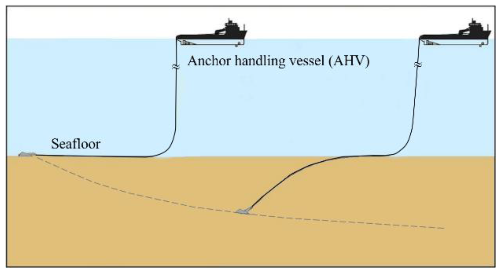
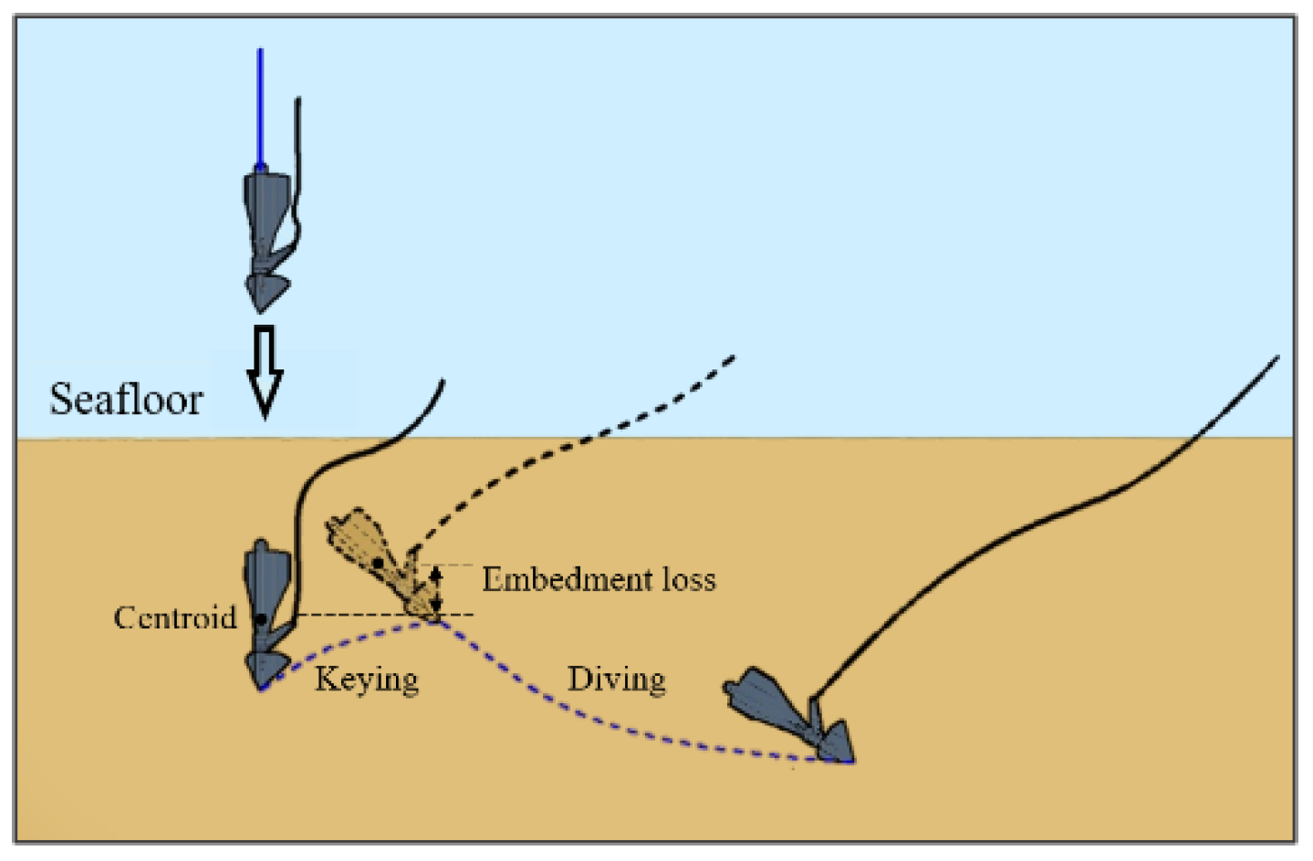
With increasing advanced technologies and innovative anchor concepts in deepwater moorings, behaviors of the anchor are turning more complex during both installation and mooring, such as 360-degree rotatable loading arm of OMNI-Max anchors (an innovative type of gravity installed anchors (GIAs)), long-distance trajectory of drag embedment plate anchors (Figure 1) [1], high strain rate of soil (up to 25 s−1) during the gravity installation of GIAs, and keying and embedment loss of OMNI-Max anchors and suction embedded plate anchors (SEPLAs) (Figure 2) [1]. These behaviors challenge the existing analytical methods for conventional anchors.
Although large deformation finite element (LDFE) analyses are able to effectively solve complicated anchor behaviors [2], theoretical methods are more efficient, convenient, and economical. The relevant theoretical achievements for drag anchors generally concentrated on predicting the trajectories of anchors in the seabed, and can be broadly classified into three kinds, i.e., the kinematic model [3,4], the plastic limit analysis [5,6,7,8,9,10] and the limit equilibrium method [11,12,13,14,15,16,17]. Owing to the complexities of problems, theoretical methods are still developing to precisely predict the comprehensive behaviors and trajectory of drag anchors.
For SEPLAs and OMNI-Max anchors, the behavior of keying and the embedment loss are of more concern. Deepwater anchors, typically the SEPLA and the OMNI-Max anchor, would encounter the phenomenon of embedment loss after initial penetration, accompanied with keying, which remarkably reduces the pullout capacity and affects the subsequent behavior of the anchor. Therefore, the maximum embedment loss (MEL) becomes a key index for design and engineering practice of these anchors. Existing studies on the MEL of SEPLAs were performed by field tests [18], centrifuge tests [19,20,21,22], plastic limit analyses [23,24], mechanistic model [25], and LDFE analyses [26,27,28,29]. Compared to SEPLAs, few studies were performed on the MEL of OMNI-Max anchors and were limited to plastic limit analyses [30,31,32], the mechanistic model [25], and LDFE analyses [33,34]. It is evident that theoretical achievements are rare for both SEPLAs and OMNI-Max anchors.
The present work introduces a unified analytical model that can address comprehensive behaviors of various deepwater anchors, developed at Tianjin University. Different to most of the existing theoretical methods, this model aims to explore the comprehensive behaviors (i.e., diving, pulling out, keying, and trajectory) and complicated mechanical properties (such as ultimate pullout capacity (UPC) and failure mode) of the anchor in both clay and sand, and directly faces the three-dimensional configuration of the anchor. This model is regarded as a unified model for different anchors, since it is developed based on unified concepts, mechanical models, and analytical procedure, in which the kinematic behaviors of the anchor are categorized uniformly into diving, pulling out, and keying; various anchor properties can be solved through the combination and analysis of the three behaviors by utilizing the least-force principle. Complexities of the problems can be combined into the unified model, such as anchor and seabed conditions, indicating the potential of the unified model to advance. Various applications demonstrate the capability and potential of the unified model.
2. The Unified Analytical Model
2.1. Definitions of Anchor Behaviors
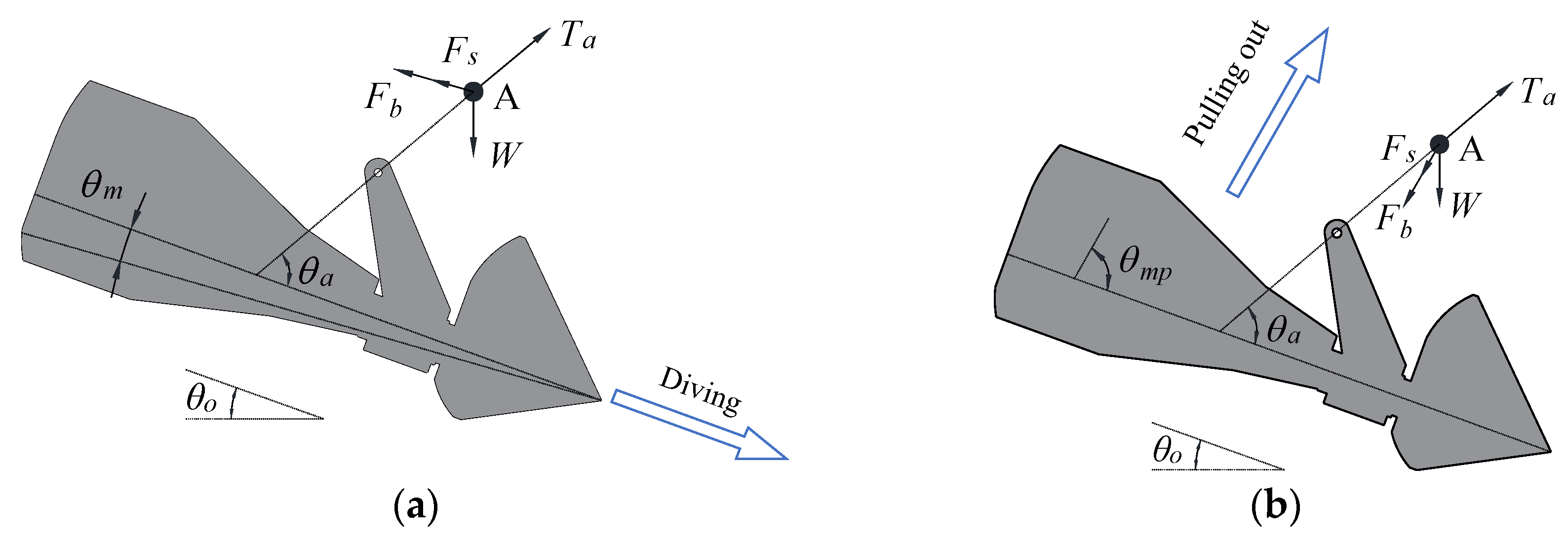
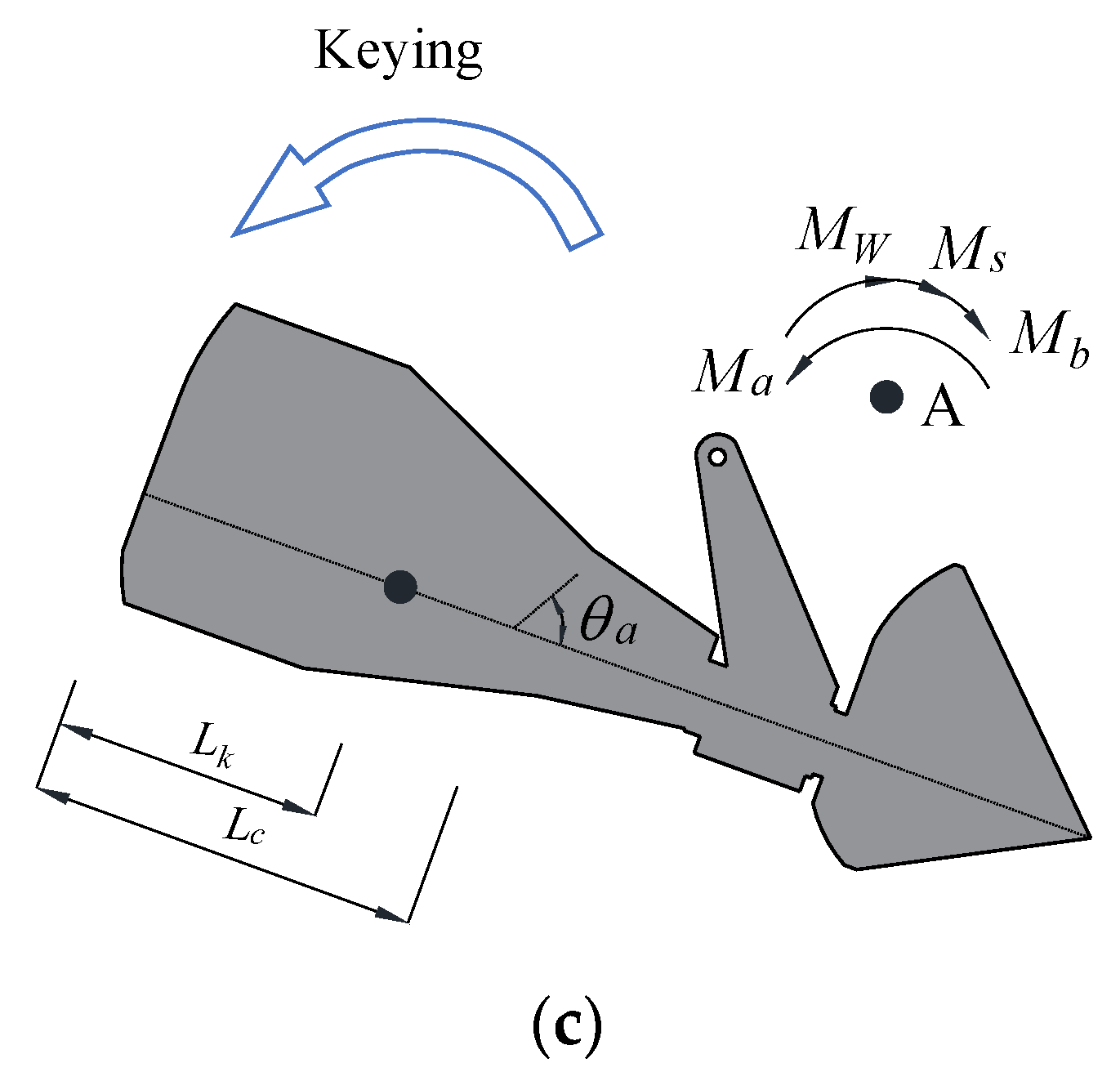
For deepwater anchors, under complicated loadings, the anchors have comprehensive behaviors in the seabed. Here, “comprehensive behaviors” means that under certain loading conditions, the anchor may key, dive, or pull out. Therefore, comprehensive behaviors can be usually categorized into three basic types, i.e., keying, diving, and pulling out. Various behaviors of the anchor, including the whole trajectory, may occur through the combination of the three basic behaviors. Keying denotes the anchor rotating around a rotational center. Diving denotes the anchor moving along the movement direction of the fluke, and pulling out denotes the anchor moving approximately perpendicular to the orientation of fluke. Both diving and pulling out can be regarded as translational motion. For different types of anchors, definitions of the three behaviors are similar but maintain a few differences.
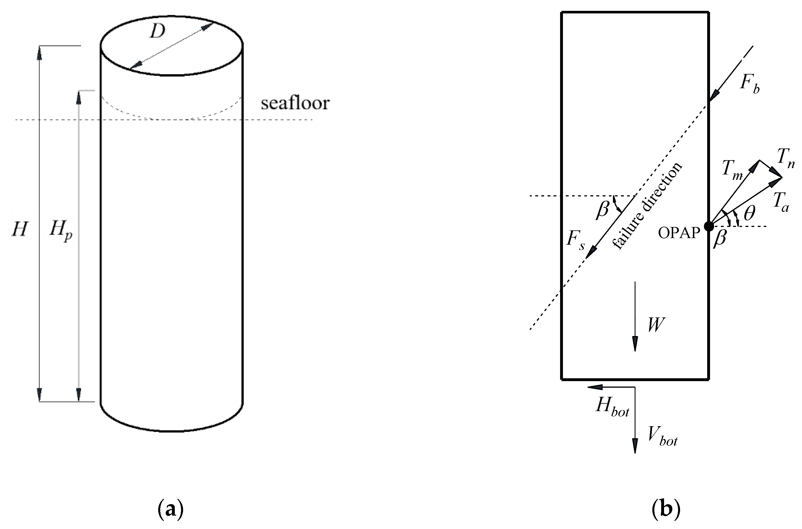
As illustrated in Figure 3, for plate anchors (such as SEPLAs and drag anchors), the movement direction of the fluke is defined as the movement direction of the plate, while for GIAs (such as torpedo anchors and OMNI-Max anchors), it is defined as the movement direction of the anchor shaft (Figure 4). Therefore, diving is defined as the movement of the anchor along the movement direction of the plate for plate anchors, and along the movement direction of the shaft for GIAs; pulling out is defined as the movement direction of the anchor approximately perpendicular to the plate orientation for plate anchors, and to the anchor shaft for GIAs. As illustrated in Figure 5, for anchor piles and suction anchors, the working performance is more concerned and pulling out is defined as the motion direction of anchor along the failure direction.
2.2. Mechanical Models
According to the force equilibrium in Figure 3, Figure 4 and Figure 5, under translating (diving and pulling out), the drag force applied at the shackle can be expressed by
According to the moment equilibrium in Figure 3, Figure 4 and Figure 5, under keying, the moment of the drag force is expressed by
For anchor piles and suction anchors, when the external force is exerted at the optimal position of the attachment point (OPAP), as shown in Figure 5, only translational motion exists in the direction of anchor failure. Meanwhile, the pullout capacity of the anchor reaches maximal. In this case, only Equation (1) is necessary, which can be further expressed by [35]
where,
The details of parameters can be found in the nomenclature list.
For drag anchors and GIAs, Equations (1) and (2) can be further expressed under a specific anchor behavior. Under diving, the drag force can be expressed by
Under pulling out, the drag force can be expressed by
where, for drag anchors,
For GIAs,
And under keying, the drag force can be can be expressed by
For drag anchors in a single soil layer, the expressions of and can be determined by the values of and (Figure 3), and written as [16]
For drag anchors in the layered soils composed of various cohesionless and cohesive layers with different soil strengths, expressions of and will become more complicated [17]. For brevity, details of this case are not presented herein.
For GIAs,
The expression of depends on the relative position of the rotational center () to the anchor structure and also exhibits various cases [36], which determines the effective shear forces and the moment arms of shear forces (closing to the rear or tip of the anchor) demarcated by the rotational center.
The anchor line equation is a necessary supplement to the mechanical models, which is expressed by [37,38]
However, for layered soils, the anchor line equation should be replaced by [39]
2.3. The Least-Force Principle
As introduced earlier, the comprehensive behaviors of the anchor are classified into three basic types. Various behaviors of the anchor, including the whole trajectory, may occur through the combination of the three basic behaviors. In the present work, the three basic behaviors of the anchors are determined by adopting the “least-force principle” proposed by Liu et al. [40]. This principle was successfully utilized to investigate various behaviors of deepwater anchors in earlier studies [16,35,41,42]. According to the principle, the actual movement state can be acquired by determining the state that can overcome the soil resistance by the least drag force. Therefore, the real rotational center, the real failure angle, the real movement state, and so on, can all be determined by the principle.
2.4. Analytical Procedure
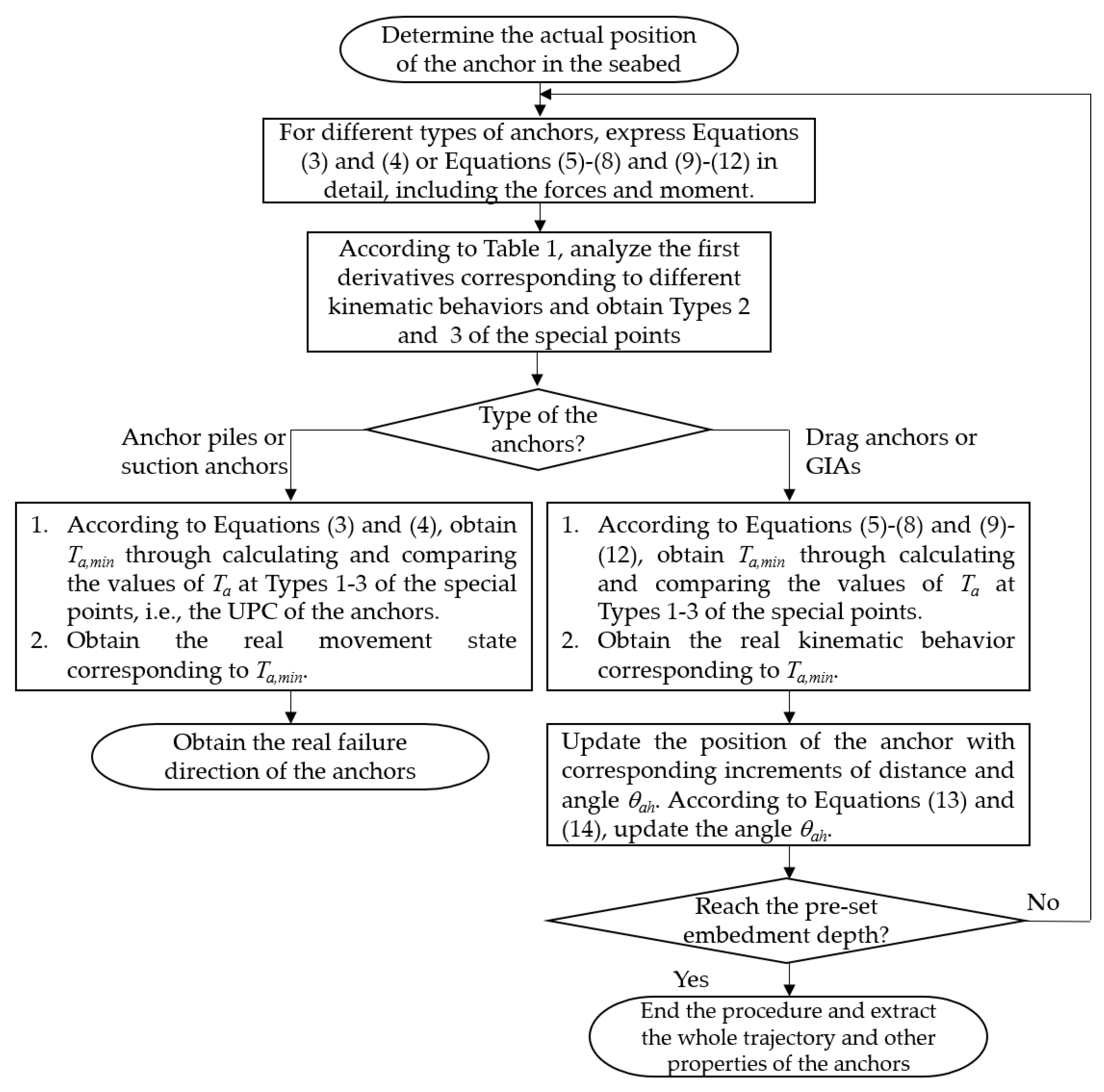
Values of four key parameters, i.e., , , , and , need to be acquired in advance to investigate the three types of behaviors. According to the least-force principle, the actual rotational center of the anchor, the actual direction of pulling out, and the actual movement direction can be derived by utilizing Equations (1) and (2), specifically Equations (3)–(12) corresponding to different anchors, and analyzing the first derivatives of with , , , and , respectively. Among the three types of behaviors, the actual movement state of the anchor can be derived with determination of the values of , i.e., the minimum values of . Table 1 lists the special points, at which the corresponding can be acquired.
The comprehensive behaviors and mechanical properties of different anchors can be solved following the flowchart (Figure 6).
3. Applications
3.1. Pullout Capacity and Failure Mode of Anchor Piles/Suction Anchors
This investigation aims to explore the pullout capacity and failure mode of anchor piles/suction anchors under inclined loading in seabed with both cohesionless and cohesive soils. By utilizing the present model, the effects of various parameters on the pullout capacity and failure mode of the anchor can be acquired, including the anchor length-to-diameter ratio , the interface friction angle , the internal friction angle , the adhesion factor , the soil cohesion at the seafloor , the submerged soil weight , the gradient of the soil cohesion with depth , the coefficient of earth pressure at rest , the end bearing capacity factor , and the reverse end-bearing capacity factor .
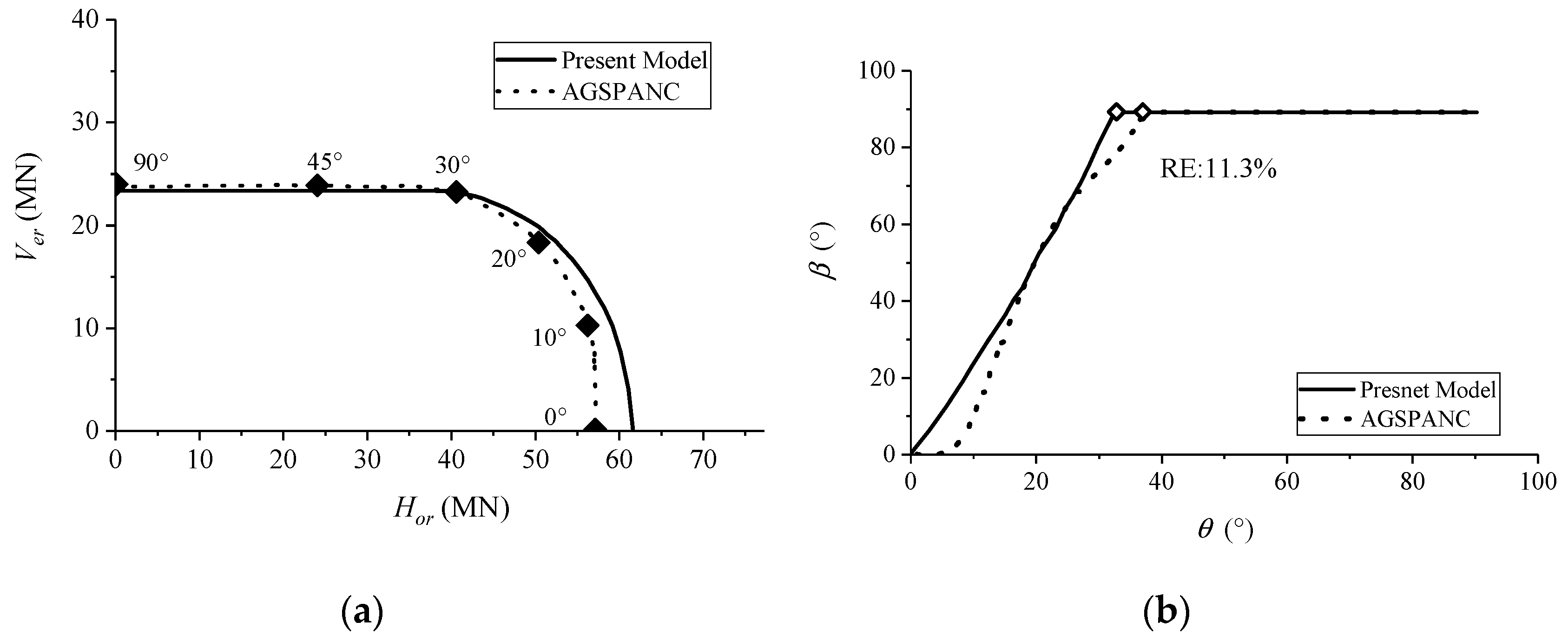
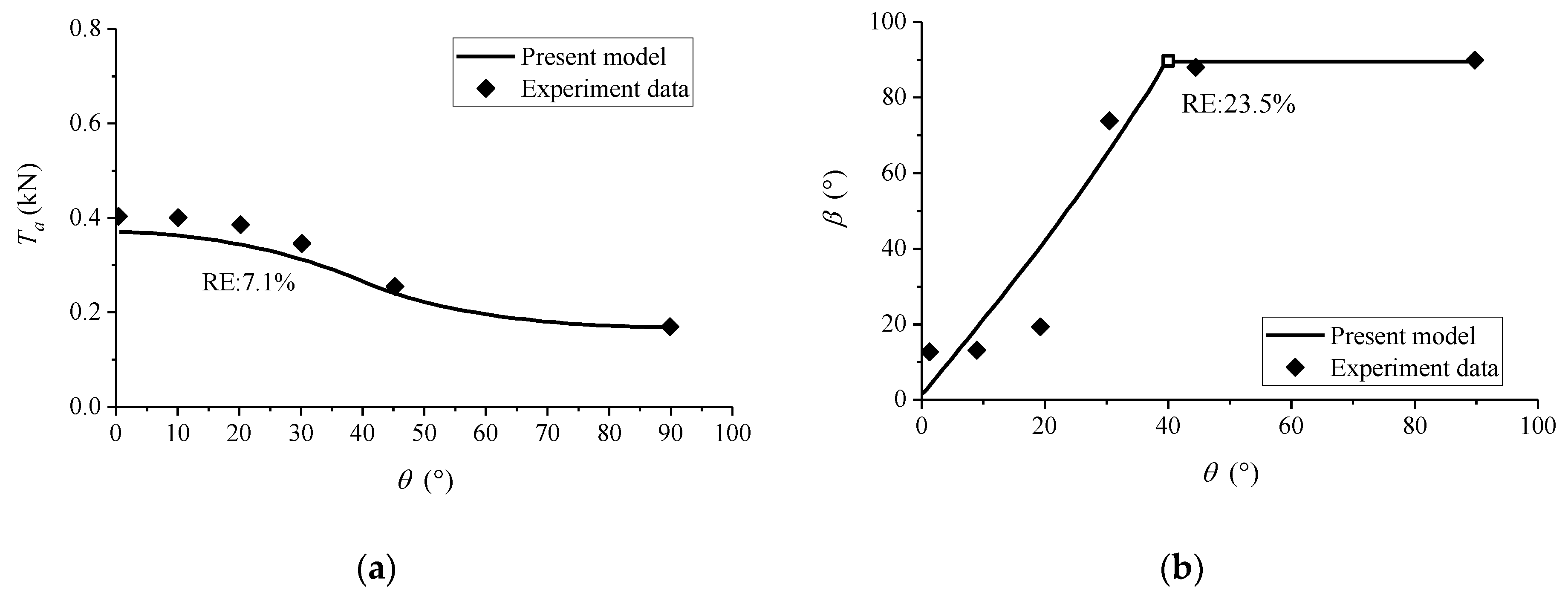
The analytical results are examined through several comparative studies, including the numerical analysis on the pullout capacity of suction anchors in clay presented by Randolph and House [43], the laboratory tests on the performance of suction anchors in clay under various loading conditions presented by EI-Sherbiny [44], the model tests on the behavior of suction anchors with various length-to-diameter ratios in sand presented by Gao et al. [45], and the centrifuge tests on the pullout capacities of suction piles in sand under inclined loading conducted by Kim et al. [46], as presented in Figure 7, Figure 8, Figure 9 and Figure 10, where RE denotes average relative error. Figure 7 illustrates that the consistency of comparative studies on the pullout capacity and the failure angle is generally good. Figure 8 shows that the theoretical model can reasonably predict the pullout capacity and failure angle of the anchor with the average relative errors of 7.1% and 23.5%, respectively. A generally good agreement between experimental data and theoretical predictions is also shown in Figure 9, where the average relative errors are 17% and 12.9% for the cases and , respectively. It is shown from Figure 10 that the theoretical model obtains good predictions of the pullout capacity with a mean relative error of 7.6%.
The accuracy of the theoretical predictions is demonstrated by the comparative studies of the model test or numerical simulation results in both cohesionless and cohesive soils. The efficiency and veracity of the theoretical model are therefore confirmed in predicting the pullout capacity and failure mode of anchor piles/suction anchors.
3.2. The Kinematic Behavior of Drag Anchors
This study aims to explore mechanical properties and comprehensive behaviors of drag anchors in the seabed with cohesionless or cohesive soils. By utilizing the present model, the effects of various parameters on the behaviors of drag anchor can be clearly known, such as the coefficient of soil resistance under keying for clay , the coefficient of soil resistance under keying for sand , the end bearing capacity factors and , the undrained shear strength at the seafloor , the adhesion factor , the submerged soil weight , the gradient of undrained shear strength with depth , the interface friction angle , the lateral soil pressure factor , the frictional coefficient , and the effective bearing width of the embedded anchor line .
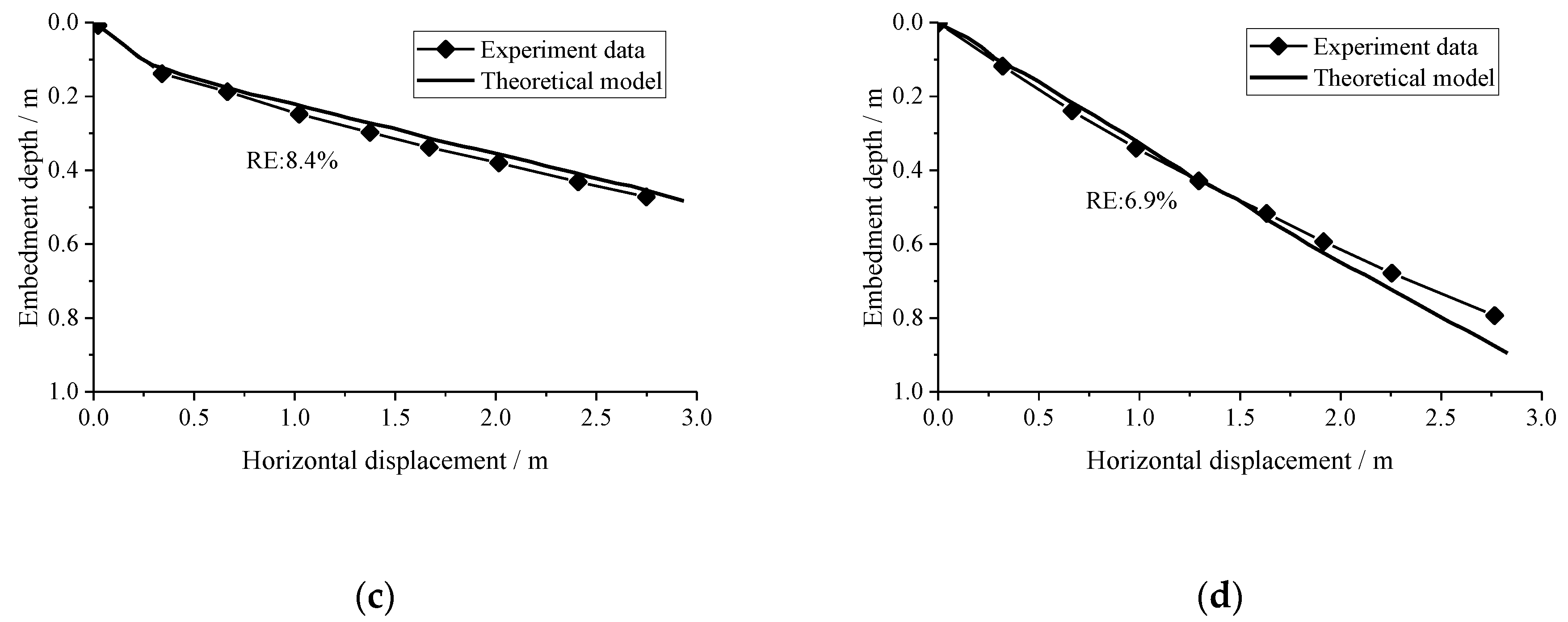
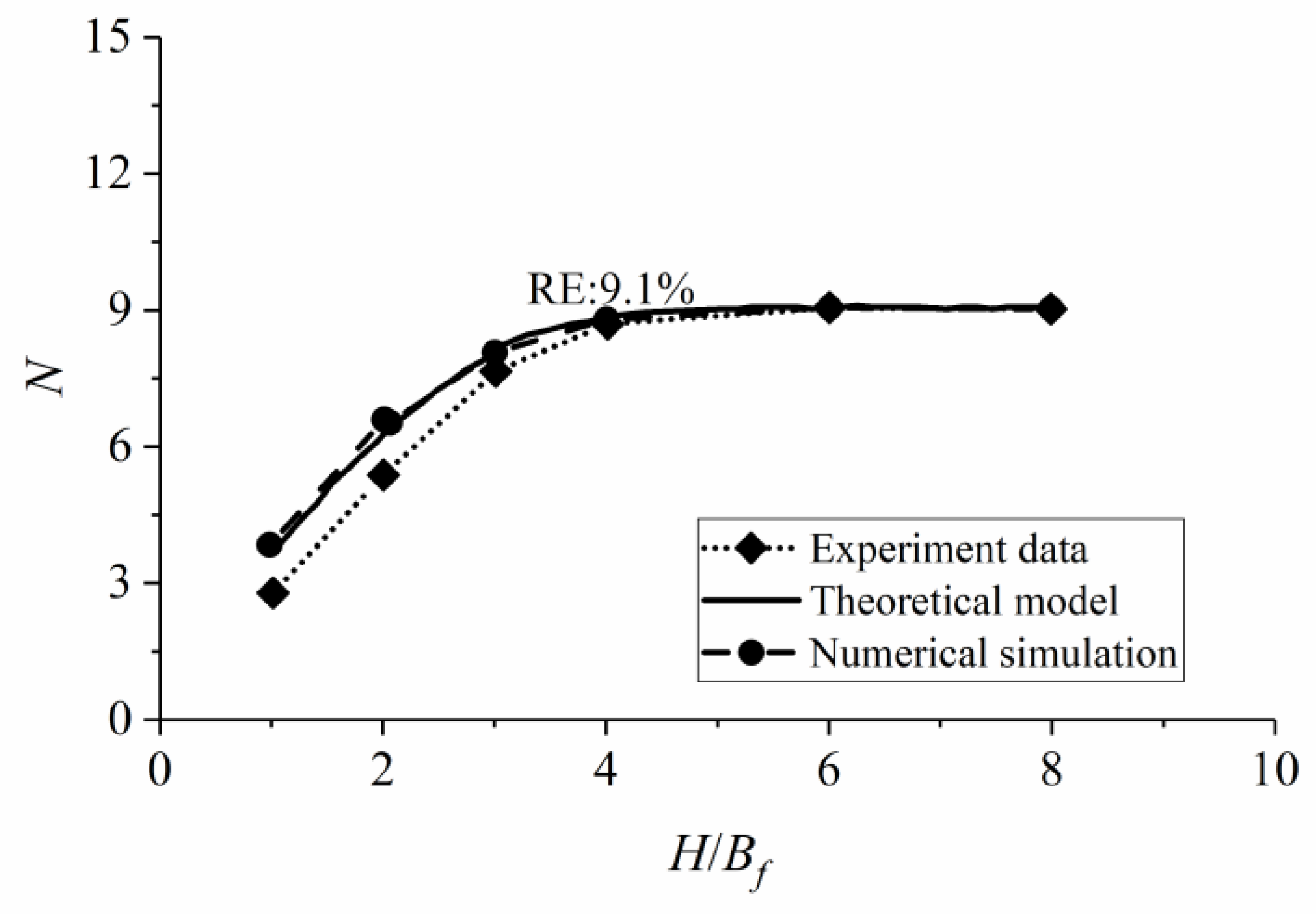
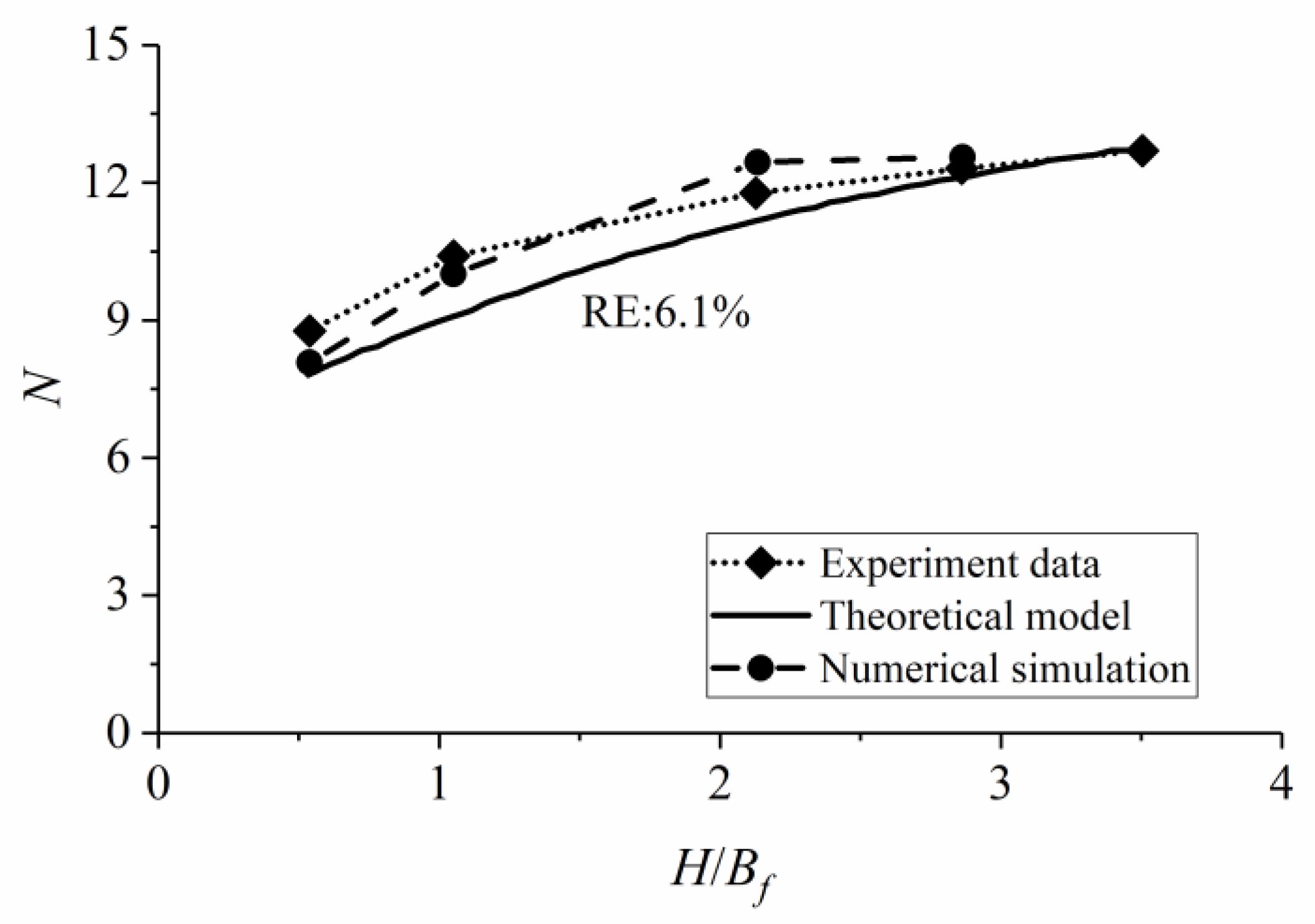
The analytical results are examined with the centrifuge model tests of the anchor trajectory in clay by O’Neill and Randolph [47], the model tests on behaviors of anchor in sand by Zhang [48], the model tests and numerical simulation of the pullout capacity of a plate anchor in uniform clay by Singh and Ramaswamy [49] and Liu et al. [50], and the centrifuge model tests and numerical simulation of the pullout capacity of plate anchor in linear clay by Chen et al. [51] and Liu et al. [50], as presented in Figure 11, Figure 12, Figure 13 and Figure 14. As shown in Figure 11, the predicted results with = 0.3 show good consistency with the experimental data. The average relative errors of the predicted results to measured values are 5.6% and 6.1% for the shank angles of 32° and 50°, respectively. Although the average relative error of 6.9% for the shank angle of 50° with = 0.5 is higher, the predicted results show good consistency with the simulation results of O’Neill and Randolph [47]. A good consistency between test results and analytical predictions is shown in Figure 12. The average relative errors of the predicted results to experimental data of embedment depth for the rectangular anchors ( 29.5° and 33.3°) and the wedge-shaped anchors ( 27.8° and 32.2°) are 10.9%, 6.1%, 8.4%, and 6.9%, respectively. As indicated in Figure 13, the results of the capacity factor obtained from the analytical model share good consistency with those from numerical and experimental results. The average relative errors of the capacity factor from theoretical results and simulation results are 9.1% and 10.5%, respectively. Figure 14 shows a good consistency between experimental data and analytical results. The average relative errors of the capacity factor from numerical results and analytical results are 4.4% and 6.1%, respectively.
These comparative results validate the accuracy and efficiency of the present model in analyzing the kinematic behavior of drag anchors in the seabed with cohesionless or cohesive soils.
3.3. The Kinematic Behavior of Drag Anchors in Layered Soils
Compared with the behavior of drag anchors in a single soil layer, it is much more complicated to analyze the anchor behavior in layered soils. Most of the earlier investigations concentrated on the behavior of anchors in a single soil layer, while in layered soils, the knowledge of the anchor behavior is severely inadequate, especially for the seabed with both cohesionless and cohesive layers. The present work intends to further investigate the behavior of an anchor under layered soils condition through utilizing the analytical model. Various cohesionless and cohesive layers with different soil strengths constitute the layered soils. The coupled effect of anchor-line in layered soils is also considered when the behavior of the anchor is analyzed. By completely expressing the complex soil resistance to the anchor in layered soils and at the adjacent interface of soils, the theoretical model can predict the behavior of the anchor in three-layered soils, which have covered common cases of layered soils for drag anchor installation. The accuracy and efficiency of the developed analytical model for layered soils are confirmed by comparative studies.
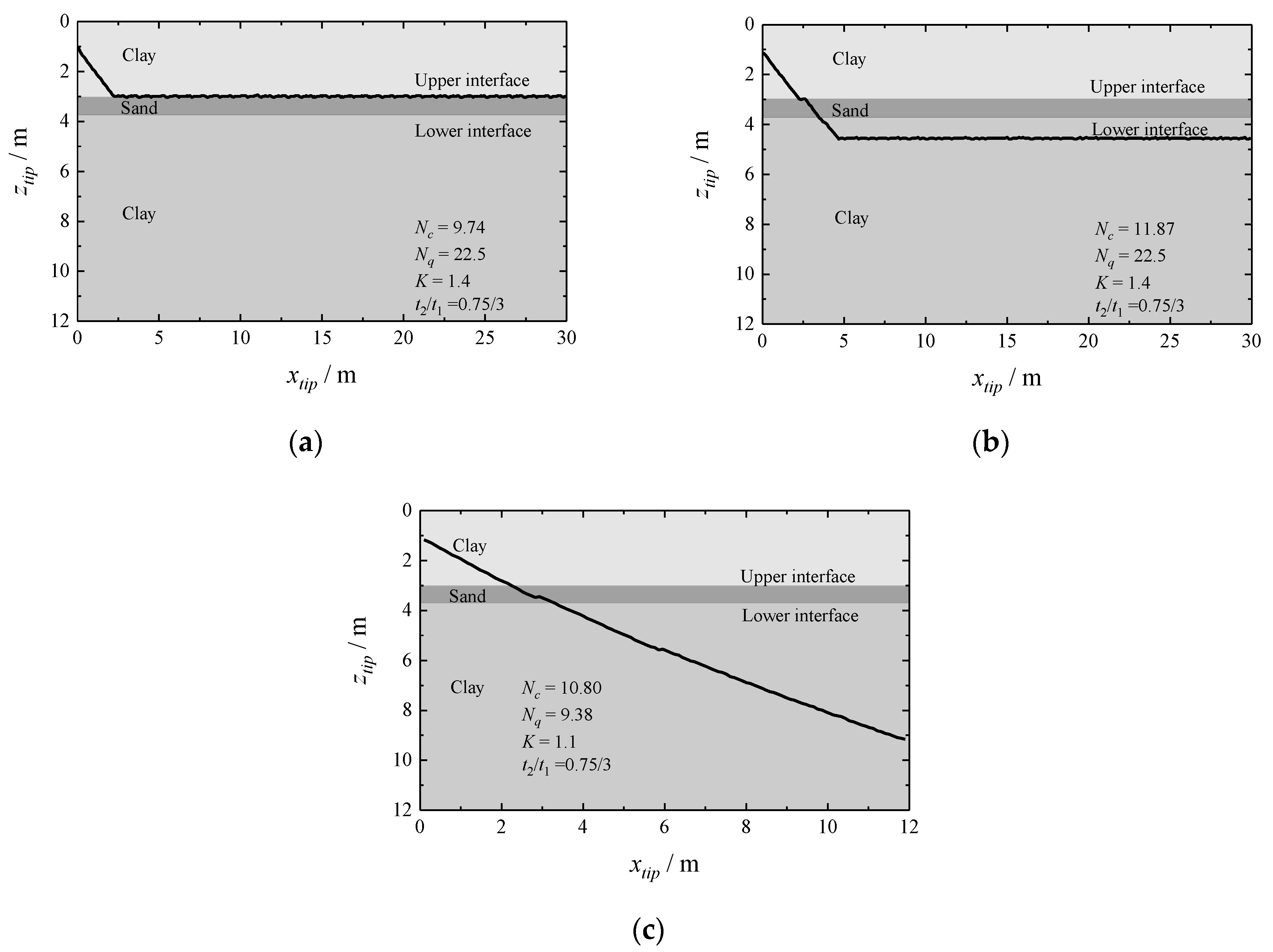
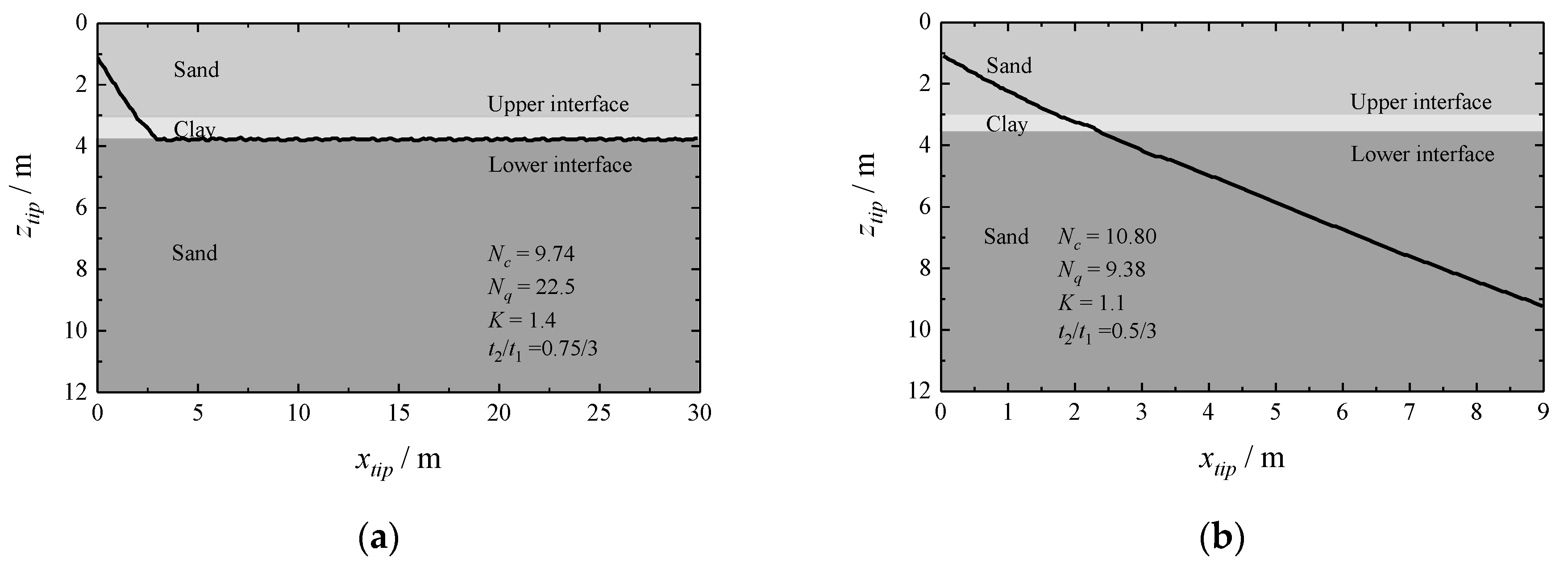
In layered soils, the variety and complexity of the anchor behavior are demonstrated in the designed analytical cases, as presented in Figure 15 and Figure 16. The present investigation derives general knowledge, i.e., when the anchor is dragged under external force in the layered soils of both clay-sand-clay and sand-clay-sand, it may completely penetrate through the layers, or fail to penetrate the whole soil layers but move along the interface of adjacent layers. Generally, when traveling from stiffer soil to softer soil, the anchor tends to penetrate through the interface; while when traveling from softer soil to stiffer soil, the anchor will probably move along the interface rather than penetrate through the interface; from softer soil to stiffer soil, the anchor may penetrate through the interface when the difference of soil resistance to the anchor in adjacent layers is small enough.
A sensible analysis is anticipated to acquire quantitative results such as the trajectory of an anchor for a specific problem in layered soils. The present analytical model provides a powerful tool to easily analyze the kinematic behavior of drag anchors in layered soils.
3.4. The Maximum Embedment Loss of SEPLAs and OMNI-Max Anchors
This study aims is to develop a unified explicit formula for calculating the maximum embedment loss (MEL) of SEPLAs and OMNI-Max anchors in clay, which takes into account all necessary influential parameters including the anchor geometry, the interactional property, the soil condition, the anchor line property, and the applied loading, to provide a fast and simple method of assessing the MEL of deepwater anchors in clay.
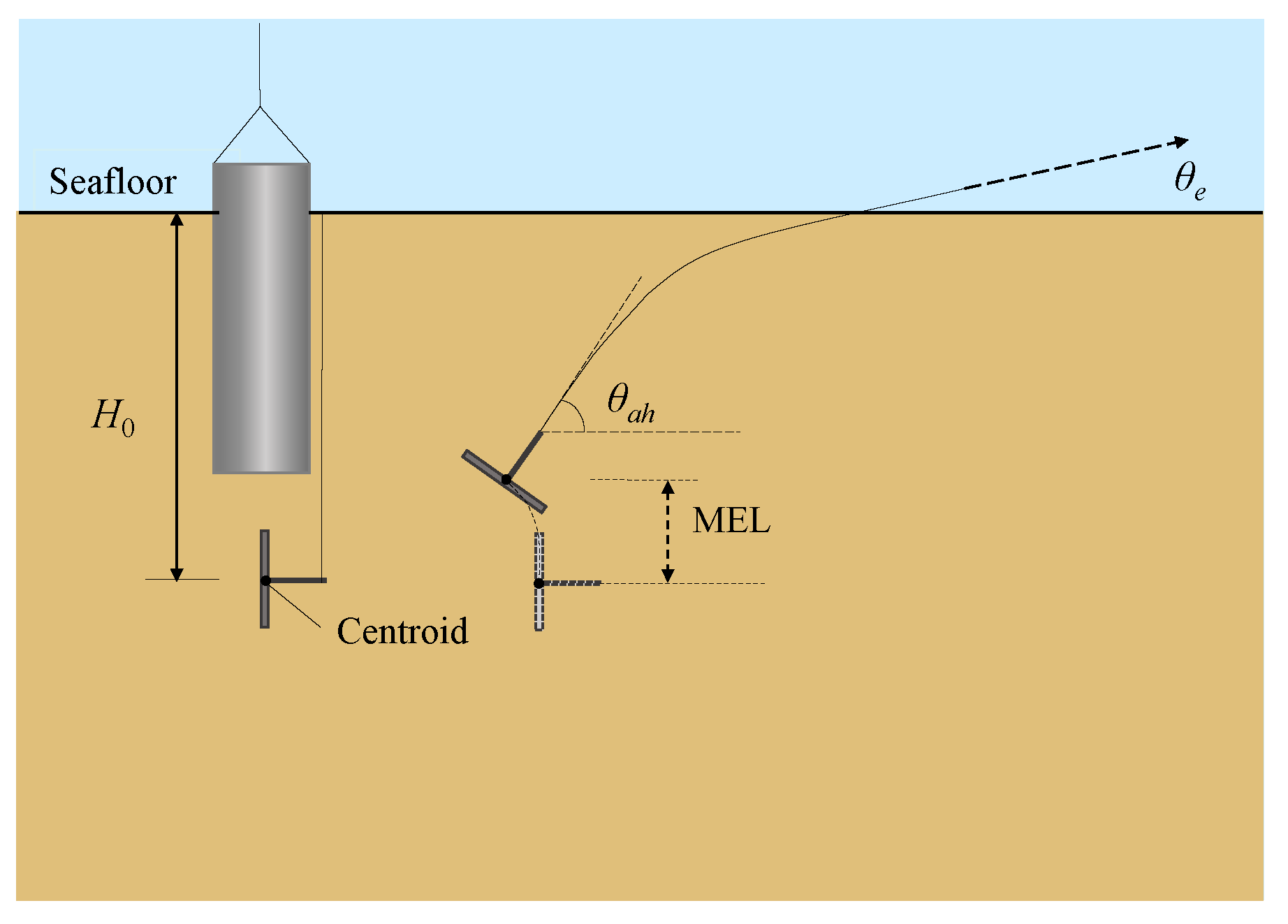
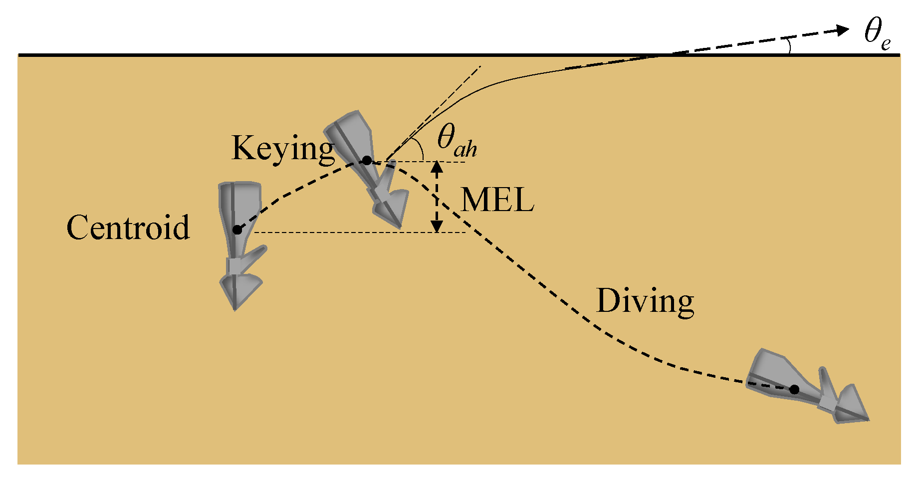
When a SEPLA just reaches the MEL, the anchor satisfies two conditions: (1) the anchor is in the critical state that changes from keying to pulling out; and (2) the applied loading at the shackle is approximately perpendicular to the plate [18,20,21], as illustrated in Figure 17. When an OMNI-Max anchor just reaches the MEL, it meets two conditions: (1) the anchor stays in a critical state from keying to translating, in a synthetical movement direction of diving and pulling out [31,33]; and (2) the applied loading at the anchor shackle is almost perpendicular to the anchor shaft [52], as illustrated in Figure 18.
Based on the knowledge above and corresponding mechanical models, the implicit set of equations of (depth of anchor centroid) can be obtained
The key to solve the MEL of anchors, , is to acquire the value of , which could be obtained from the implicit sets of equations of , i.e., Equations (15) and (16). However, the value of cannot be directly solved through Equations (15) and (16). By performing parametric studies and nonlinear regressive analyses, a unified nondimensional MEL for both SEPLAs and OMNI-Max anchors, , can be expressed by [25]
where c1–c12 are coefficients derived from the best-fitting analyses based on the results of the analytical model, whose values are different for SEPLAs and OMNI-Max anchors, as listed in Table 2.
To examine the unified explicit formula, i.e., Equation (17), all data available from publications are collected to perform comparative studies, including the centrifuge model tests by Gaudin et al. [20], O’Loughlin et al. [21], and Gaudin et al. [22] for SEPLAs; and the plastic limit analyses by Liu et al. [31]; the LDFE analyses by Zhao and Liu [33]; and the model tests by Liu et al. [53] for OMNI-Max anchors. Meanwhile, the analytical predictions are compared with the predictions from other methods [27,28,33]. The comparative studies confirm the veracity and reliability of the unified explicit formula for both SEPLAs and OMNI-Max anchors. Compared to existing methods, the explicit formula performs superiorly in easiness, efficiency, and applicability [25].
3.5. The Kinematic Behavior of OMNI-Max Anchors
This study aims to explore comprehensive behaviors of OMNI-Max anchors in the seabed with either sandy or clayey soil. By utilizing the present model, the effects of various parameters on the behaviors of anchor can be clearly known, including , b, , , , , , , , , and .
The parametric studies indicate that the parameters , , , , , and have a major influence on the trajectory of anchor in clay, while the parameters , , , , , and have a major influence on the trajectory of anchor in sand. The MEL increases with increasing values of , , and in clay, and with the increase of , , and in sand. The penetration depth increases with the increases of , , and in clay, and with the increases of , , , and in sand.
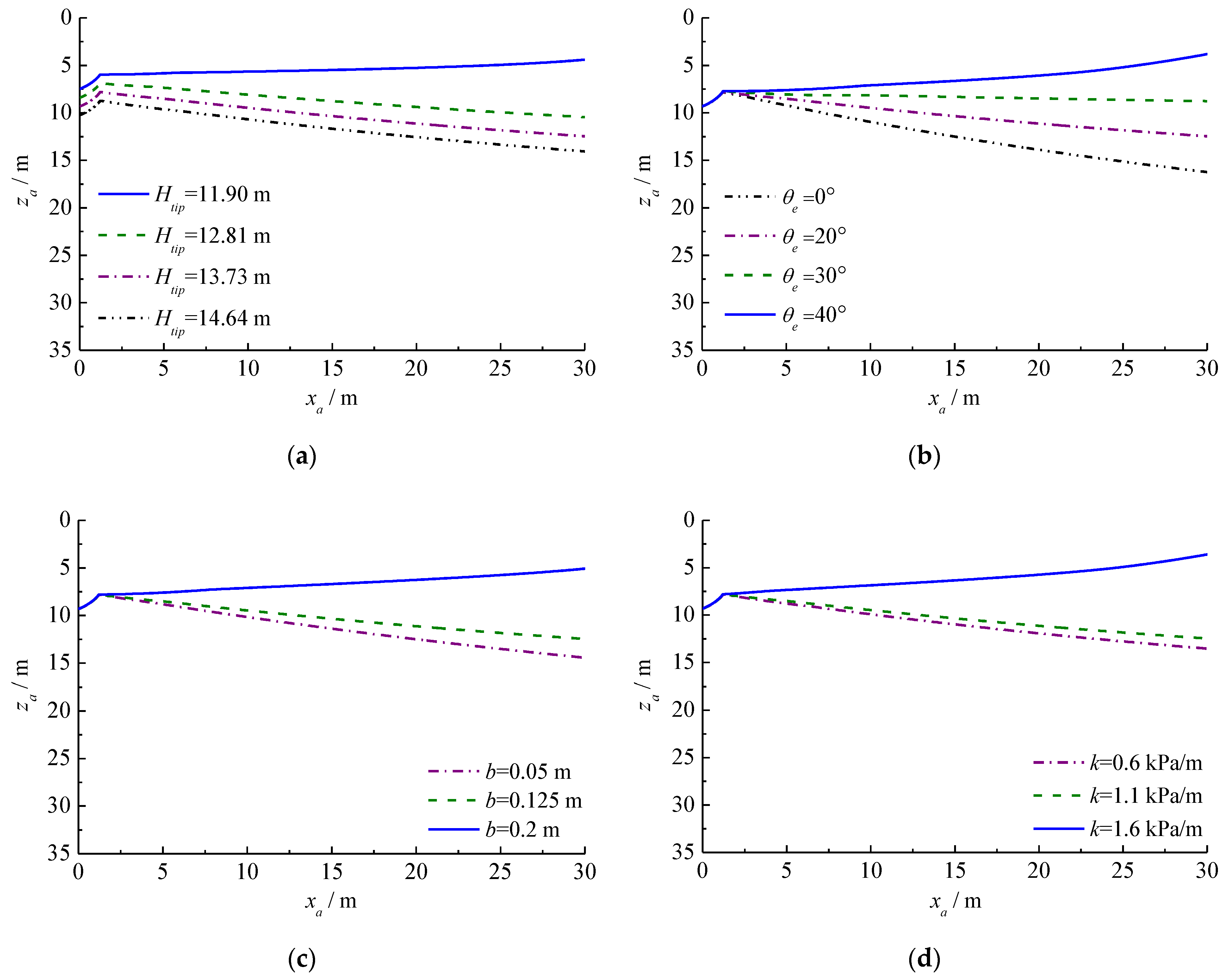
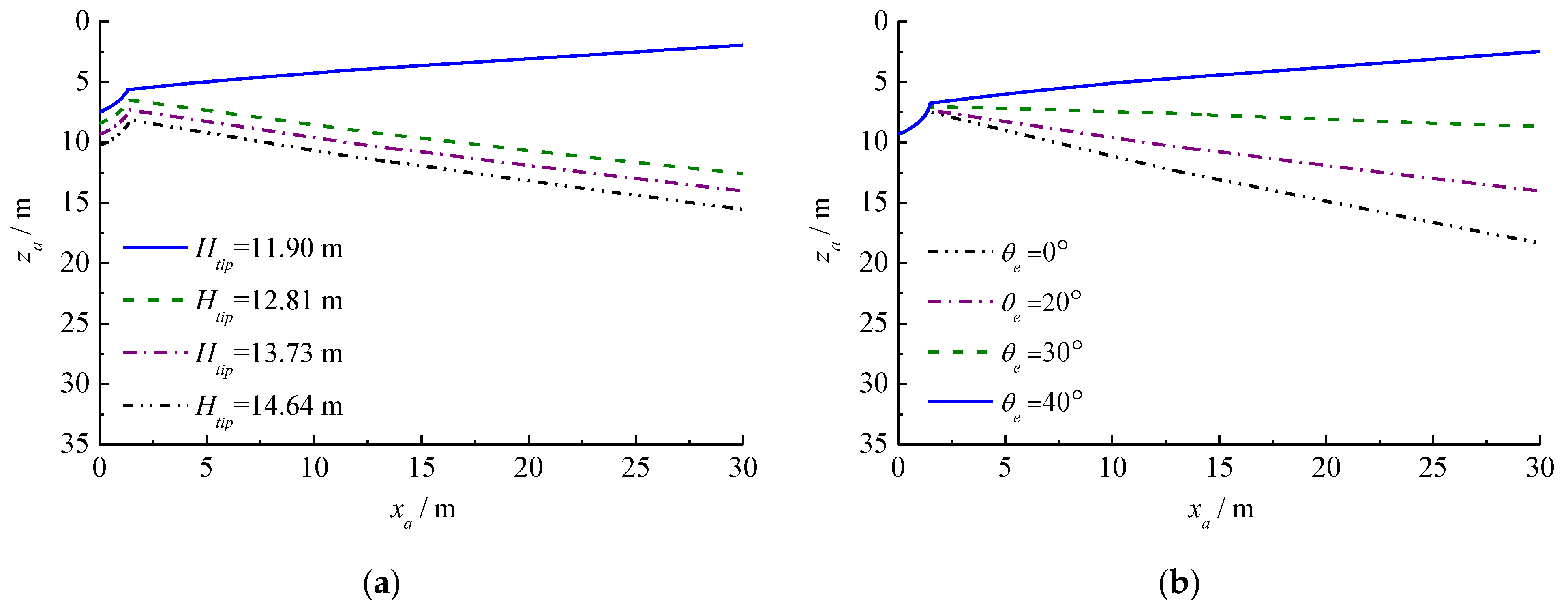
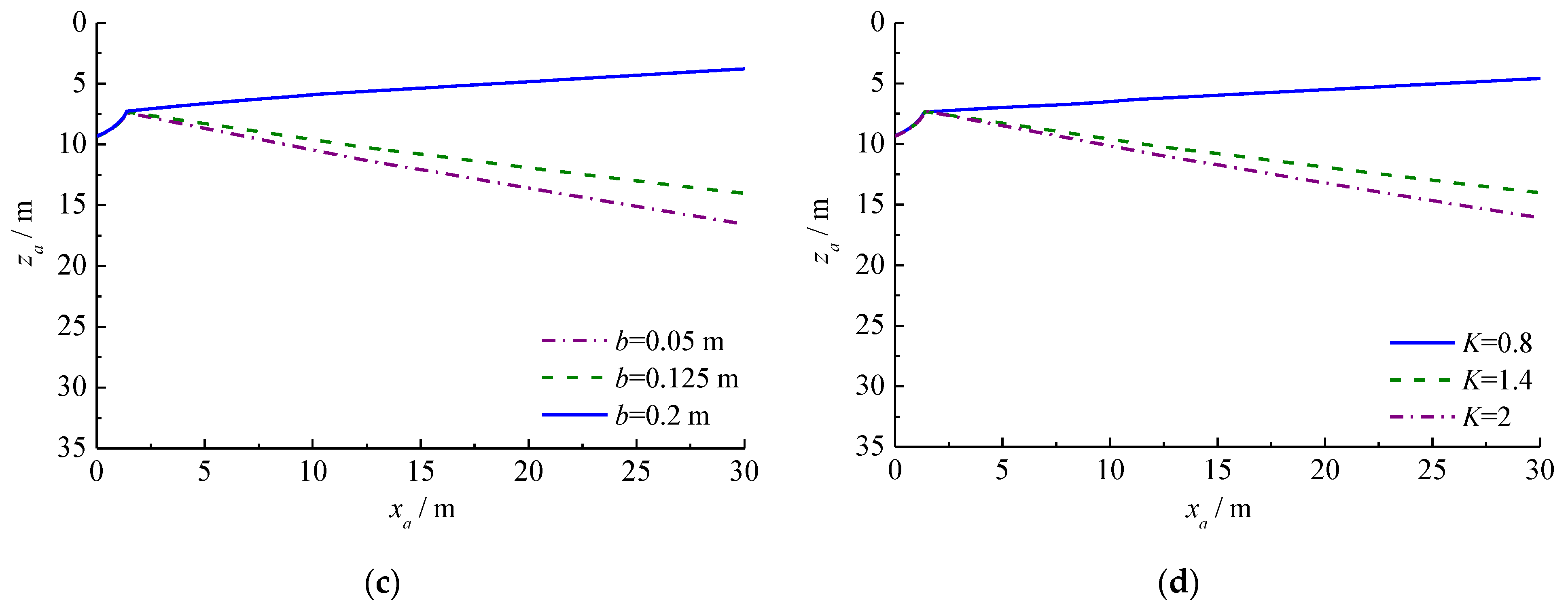
The embedment loss usually happens at the initial stage of the anchor trajectory, then the anchor may dive further or be pulled out gradually, meaning failure of the anchor in the latter case. The failure induced by the embedment loss of the anchor is explored through investigating different influential parameters, as presented in Figure 19 and Figure 20. If the conditions, 11.90 m, 40°, 1.6 kPa/m, and 0.2 m are satisfied simultaneously, the anchor most easily fails in clay after the embedment loss. If the conditions, 11.90 m, 40°, ≤ 0.8, and 0.2 m are satisfied simultaneously, the anchor most easily fail in sand after the embedment loss [36]. However, systematic studies are expected next on the problem of embedment loss-induced anchor failure.
4. Conclusions
This paper draws an outline of a unified analytical model that is capable of addressing comprehensive behaviors of various deepwater anchors, which was developed and is still developing at Tianjin University. Features of the unified model can be summarized as:
- (1)
- Different to existing theoretical methods, the present model is a unified analytical model that can explore complicated mechanical properties (such as failure mode, UPC, and bearing capacity) and comprehensive behaviors (such as diving, pulling out, keying, and trajectory) of the anchor in both clay and sand, and directly faces the three-dimensional configuration of the anchor.
- (2)
- This model can effectively analyze the challenging problems with complexities and varieties of deepwater anchors, proving the capability and potentiality of the unified model, as demonstrated by five application cases.
- (3)
- This model can easily be advanced further. By correctly reflecting the mechanism and precisely describing soil resistance to the anchor, the unified model is expected to play an irreplaceable role in exploring complex unsolved and even emerging problems of deepwater anchors.
Author Contributions
Data analyses: H.L., Y.Y., J.P.—Writing—original draft: H.L.—Writing—review & editing: Y.Y.—Supervision: H.L. All authors have read the manuscript and agreed to the submission.
Funding
This research was funded by the National Natural Science Foundation of China, grant numbers 51539008 and 51890915.
Institutional Review Board Statement
Not applicable.
Informed Consent Statement
Not applicable.
Data Availability Statement
The data presented in this study are available on request from the corresponding author.
Conflicts of Interest
The authors declare no conflict of interest.
Nomenclature
| anchor annulus area | |
| total projected area of the anchor on to the plane perpendicular to the translating direction, i.e., effective end bearing area of the anchor (, for anchor piles/suction anchors only) | |
| anchor bottom area | |
| rotational coefficients reflecting the soil and anchor properties | |
| bottom area of the soil plug inside the anchor | |
| effective shear area of the anchor in the translating direction | |
| effective shear area of the GIA, except the coplanar area with the lateral side of the shank | |
| effective shear area of the anchor projected to the primary plane of the fluke | |
| effective shear area of the anchor projected to the plane perpendicular to the primary plane in the translating direction | |
| effective shear area of the GIA, excluding | |
| effective bearing width of the embedded anchor line | |
| plate width of the SEPLA or length of the OMNI-Max anchor | |
| fluke width | |
| , average cohesion of soil at the mid-depth of the anchor | |
| , cohesion of soil at the bottom of the anchor | |
| cohesion of soil at the seafloor | |
| c1–c12 | coefficients in Equation (17) |
| anchor diameter | |
| diameter of the anchor line | |
| padeye eccentricity (normal to the shaft) | |
| padeye offset of the anchor (parallel to the shaft) | |
| multiplier of effective width in the normal direction to the anchor line | |
| total end bearing in the translating direction of anchor | |
| total shear resistance in the translating direction of anchor | |
| height of anchor piles/suction anchors | |
| horizontal shear resistance acting on the anchor bottom | |
| horizontal component of UPC | |
| anchor penetration depth | |
| initial penetration depth of the tip of a GIA | |
| gradient of undrained shear strength or the soil cohesion with depth | |
| coefficient of the maximum bearing stress | |
| lateral soil pressure factor | |
| coefficient of earth pressure at rest | |
| lower boundary of the anchor line | |
| distance from the fluke-shank connection point to the rear of the fluke | |
| distance from the intersection between the drag force and the fluke to the rear of the fluke | |
| length of the fluke | |
| distance from the rotational center to the rear of the fluke | |
| length of the shank | |
| moment of drag force | |
| total end bearing moment | |
| total shear moment | |
| total gravity moment | |
| soil resistance coefficient under keying for clay | |
| soil resistance coefficient under keying for sand | |
| capacity factor | |
| , | end-bearing capacity factors |
| reverse end-bearing capacity factor | |
| end bearing capacity factor for the anchor line | |
| undrained shear strength for clay, or soil pressure for sand | |
| soil resistance | |
| soil resistance in the i-th layer | |
| undrained shear strength of clay | |
| undrained shear strength at the seafloor | |
| plate thickness of SEPLAs or fin width of OMNI-Max anchors | |
| , | thicknesses of the first and the second layers of soils |
| drag force, or mooring tension applied at the shackle of the anchor | |
| minimum value of | |
| line tension corresponding to in the i-th layer of soils | |
| tangential component of to the direction of failure | |
| normal component of to the direction of failure | |
| upper boundary of the anchor line | |
| vertical resistance acting on the anchor bottom | |
| vertical component of UPC | |
| submerged anchor weight, or total submerged weight of the anchor and the soil plug inside the anchor (for anchor piles and suction anchors) | |
| submerged shank weight | |
| horizontal displacement of the shackle | |
| horizontal displacement of the fluke tip | |
| soil depth | |
| depth of shackle | |
| anchor centriod depth | |
| soil depth in the i-th layer | |
| distance between the embedment depth at the MEL and the initial embedment depth | |
| fluke tip depth | |
| anchor line depth corresponding to in the i-th layer of soils | |
| adhesion factor | |
| failure direction, or failure angle to the horizontal of the anchor | |
| interface friction angle | |
| deviation angle to the fluke top surface | |
| internal friction angle | |
| submerged soil weight | |
| submerged anchor weight | |
| ξ | |
| ζ | |
| inclination factor | |
| frictional coefficient | |
| frictional coefficient in the i-th layer of soils | |
| drag angle, mooring angle, or tension angle to the horizontal at the shackle of the anchor | |
| drag angle to the top surface of the fluke at the shackle | |
| drag angle to the horizontal at the shackle | |
| loading angle of the anchor line to the horizontal at the seafloor | |
| tension angle of the anchor line to the horizontal at the shackle of the anchor in the i-th layer | |
| tension angle of the anchor line corresponding to in the i-th layer of soils | |
| movement direction or angle of the anchor to the top surface of the fluke | |
| movement direction or angle of the anchor to the horizontal | |
| direction of pulling out or failure angle of the anchor to the top surface of the fluke | |
| orientation of the top surface of the fluke to the horizontal | |
| shank angle to the top surface of the fluke | |
| tension angle of the anchor line corresponding to in the i-th layer of soils | |
| , effective stress at the anchor bottom | |
| ηF | in Equation (15); in Equation (16) |
| ηM | in Equation (15); in Equation (16) |
| total forces in the direction of translating, including soil resistance and anchor weight | |
| total moments of forces in the direction of translating |
References
- Liu, H.X.; Li, Z.; Zhang, Y.M. Offshore geotechnical problems in deepwater mooring techniques for large floating structures. Am. J. Eng. Appl. Sci. 2018, 11, 598–610. [Google Scholar] [CrossRef]
- Zhao, Y.B.; Liu, H.X. Key techniques in simulating comprehensive anchor behaviors by large deformation finite element analysis. J. Offshore Mech. Arct. Eng. 2018, 140, 012001. [Google Scholar] [CrossRef]
- Liu, H.X.; Liu, C.L.; Yang, H.T.; Li, Y.; Zhang, W.; Xiao, Z.J. A novel kinematic model for drag anchors in seabed soils. Ocean Eng. 2012, 49, 33–42. [Google Scholar] [CrossRef]
- Liu, H.X.; Liu, C.L.; Zhao, Y.B.; Wang, C. Reverse catenary equation of the embedded installation line and application to the kinematic model for drag anchors. Appl. Ocean Res. 2013, 43, 80–87. [Google Scholar] [CrossRef]
- Bransby, M.F.; O’Neill, M.P. Drag anchor fluke-soil interaction in clays. In Proceedings of the International Symposium on Numerical Models in Geomechanics, Rotterdam, The Netherlands, 1–3 September 1999. [Google Scholar]
- Aubeny, C.P.; Chi, C. Mechanics of drag embedment anchors in a soft seabed. J. Geotech. Geoenviron. Eng. 2010, 136, 57–68. [Google Scholar] [CrossRef]
- Aubeny, C.; Chi, C.M. Analytical model for vertically loaded anchor performance. J. Geotech. Geoenviron. Eng. 2014, 140, 14–24. [Google Scholar] [CrossRef]
- Wang, L.Z.; Shen, K.M.; Li, L.L.; Guo, Z. Integrated analysis of drag embedment anchor installation. Ocean Eng. 2014, 88, 149–163. [Google Scholar] [CrossRef]
- Cong, B.L.; Wang, Z.T.; Chan, A.H.C.; Yang, Q. Analytical model for vertically loaded anchor performance with a bridle shank. Comput. Geotech. 2017, 82, 85–98. [Google Scholar] [CrossRef]
- Wu, X.N.; Chow, Y.K.; Leung, C.F. Kinematic analysis of drag anchor installation trajectory considering both shallow and deep anchor behavior of horizontal fluke. Appl. Ocean Res. 2020, 100, 102157. [Google Scholar] [CrossRef]
- Stewart, W.P. Drag embedment anchor performance prediction in soft soils. In Proceedings of the Twenty-fourth Offshore Technology Conference, Houston, TX, USA, 4–7 May 1992. [Google Scholar]
- Neubecker, S.R.; Randolph, M.F. The kinematic behavior of drag anchors in sand. Can. Geotech. J. 1996, 33, 584–594. [Google Scholar] [CrossRef]
- Neubecker, S.R.; Randolph, M.F. The performance of drag anchor and chain systems in cohesive soil. Mar. Georesour. Geotechnol. 1996, 14, 77–96. [Google Scholar] [CrossRef]
- Ruinen, R.M. Penetration analysis of drag embedment anchors in soft clays. In Proceedings of the Fourteenth International Offshore and Polar Engineering Conference, Toulon, France, 23–28 May 2004. [Google Scholar]
- Zhang, W.; Liu, H.X.; Li, X.Z.; Li, Q.P.; Cao, J. An analytical method for positioning drag anchors in seabed soils. China Ocean Eng. 2015, 29, 49–64. [Google Scholar] [CrossRef]
- Peng, J.S.; Liu, H.X. Analytical study on comprehensive behaviors of drag anchors in the seabed. Appl. Ocean Res. 2019, 90, 101855. [Google Scholar] [CrossRef]
- Peng, J.S.; Liu, H.X.; Liang, K.; Xiao, Z. A theoretical model for analyzing the behavior of drag anchors in layered soils. Ocean Eng. 2021, 222, 108568. [Google Scholar] [CrossRef]
- Wilde, B.; Treu, H.; Fulton, T. Field testing of suction embedded plate anchors. In Proceedings of the 11th International Offshore and Polar Engineering Conference, ISOPE, Stavanger, Norway, 19–24 June 2001; pp. 544–551. [Google Scholar]
- Song, Z.; Hu, Y.; Wang, D.; O’Loughlin, C.D. Pullout capacity and rotational behaviour of square anchors. In Proceedings of the 6th International Conference on Physical Modelling in Geomechanics, Hong Kong, China, 4–6 August 2006; Taylor & Francis: London, UK, 2006; pp. 1325–1331. [Google Scholar]
- Gaudin, C.; O’Loughlin, C.D.; Randolph, M.F.; Lowmass, A.C. Influence of the installation process on the performance of suction embedded plate anchors. Géotechnique 2006, 56, 381–391. [Google Scholar] [CrossRef]
- O’Loughlin, C.D.; Lowmass, A.C.; Gaudin, C.; Randolph, M.F. Physical modelling to assess keying characteristics of plate anchors. In Proceedings of the 6th International Conference on Physical Modelling in Geotechnics, Hong Kong, China, 4–6 August 2006; pp. 659–666. [Google Scholar]
- Gaudin, C.; Tham, K.H.; Ouahsine, S. Keying of plate anchors in NC clay under inclined loading. Int. J. Offshore Polar Eng. 2009, 19, 135–142. [Google Scholar]
- Yang, M.; Aubeny, C.P.; Murff, J.D. Behavior of suction embedded plate anchors during the keying process. J. Geotech. Geoenviron. Eng. 2012, 138, 174–183. [Google Scholar] [CrossRef]
- Cassidy, M.J.; Gaudin, C.; Randolph, M.F.; Wong, P.C.; Wang, D.; Tian, Y. A plasticity model to assess the keying of plate anchors. Géotechnique 2012, 62, 825–836. [Google Scholar] [CrossRef]
- Liu, H.X.; Liang, K.; Peng, J.S.; Xiao, Z. A unified explicit formula for calculating the maximum embedment loss of deepwater anchors in clay. Ocean Eng. 2021, 236, 109454. [Google Scholar] [CrossRef]
- Yu, L.; Liu, J.; Kong, X.; Hu, Y. Three-dimensional numerical analysis of the keying of vertically installed plate anchors in clay. Comput. Geotech. 2009, 36, 558–567. [Google Scholar] [CrossRef]
- Song, Z.; Hu, Y.; O’Loughlin, C.D.; Randolph, M.F. Loss in anchor embedment during plate anchor keying in clay. J. Geotech. Geoenviron. Eng. 2009, 135, 1475–1485. [Google Scholar] [CrossRef]
- Wang, D.; Hu, Y.; Randolph, M.F. Keying of rectangular plate anchors in normally consolidated clays. J. Geotech. Geoenviron. Eng. 2011, 137, 1244–1253. [Google Scholar] [CrossRef]
- Zhao, Y.B.; Liu, H.X.; Li, P.D. An efficient approach to incorporate anchor line effects into the coupled Eulerian–Lagrangian analysis of comprehensive anchor behaviors. Appl. Ocean Res. 2016, 59, 201–215. [Google Scholar] [CrossRef]
- Wei, Q.C.; Cassidy, M.J.; Tian, Y.H.; Gaudin, C.; O’Loughlin, C.D. Behaviour of OMNI-Max anchors under chain loading. In Proceedings of the 3rd International Symposium Frontiers in Offshore Geotechnics, ISFOG, Leiden, The Netherlands, 10–12 June 2015; pp. 925–930. [Google Scholar]
- Liu, J.; Lu, L.; Hu, Y.X. Keying behavior of gravity installed plate anchor in clay. Ocean Eng. 2016, 114, 10–24. [Google Scholar] [CrossRef]
- Han, C.C.; Liu, D.; Liu, J. Keying process of the OmniMax anchor shallowly embedded in undrained normally consolidated clay. J. Waterw. Port Coast. Ocean Eng. 2018, 144, 04018008. [Google Scholar] [CrossRef]
- Zhao, Y.B.; Liu, H.X. Toward a quick evaluation of the performance of gravity installed anchors in clay: Penetration and keying. Appl. Ocean Res. 2017, 69, 148–159. [Google Scholar] [CrossRef]
- Kim, Y.H.; Hossain, M.S. Dynamic installation, keying and diving of OMNI-Max anchors in clay. Géotechnique 2017, 67, 78–85. [Google Scholar] [CrossRef] [Green Version]
- Peng, J.S.; Liu, H.X.; Zhao, Y.B.; Liang, K. Failure mode and pullout capacity of anchor piles in soils with cohesive and cohesionless properties. Mar. Georesour. Geotechnol. 2020, 38, 1056–1069. [Google Scholar] [CrossRef]
- Peng, J.S. The Unified Analytical Model and Applications of Complicated Mechanical Properties and Kinematic Behaviors of Deepwater Anchors. Ph.D. Thesis, Tianjin University, Tianjin, China, 2020. [Google Scholar]
- Neubecker, S.R.; Randolph, M.F. Profile and frictional capacity of embedded anchor chains. J. Geotech. Eng. 1995, 121, 797–803. [Google Scholar] [CrossRef]
- Zhang, W.; Liu, H.X.; Zhao, Y.B.; Yue, Y.Z. Interactional properties between drag anchor and installation line. J. Geotech. Geoenviron. Eng. 2014, 140, 04013018. [Google Scholar] [CrossRef]
- Liu, H.X.; Peng, J.S.; Liang, K.; Xiao, Z. The behavior of anchor lines embedded in layered soils. Ocean Eng. 2019, 190, 106424. [Google Scholar] [CrossRef]
- Liu, H.X.; Zhang, W.; Liu, C.L.; Hu, C. Movement direction of drag anchors in seabed soils. Appl. Ocean Res. 2012, 34, 78–95. [Google Scholar] [CrossRef]
- Liu, H.X.; Wang, C.; Zhao, Y.B. Analytical study of the failure mode and pullout capacity of suction anchors in clay. Ocean Syst. Eng. 2013, 3, 79–95. [Google Scholar] [CrossRef]
- Liu, H.X.; Peng, J.S.; Zhao, Y.B. Analytical study of the failure mode and pullout capacity of suction anchors in sand. Ocean Syst. Eng. 2015, 5, 279–299. [Google Scholar] [CrossRef]
- Randolph, M.F.; House, A.R. Analysis of suction caisson capacity in clay. In Proceedings of the 34th Annual Offshore Technology Conference, Houston, TX, USA, 6–9 May 2002. [Google Scholar]
- EI-Sherbiny, R.M. Performance of Suction Caisson Anchors in Normally Consolidated Clay. Ph.D. Thesis, The University of Texas at Austin, Austin, TX, USA, 2005. [Google Scholar]
- Gao, Y.F.; Qiu, Y.; Li, B.; Li, D.Y.; Sha, C.M.; Zheng, X. Experimental studies on the anti-uplift behavior of the suction caissons in sand. Appl. Ocean Res. 2013, 43, 37–45. [Google Scholar] [CrossRef]
- Kim, K.O.; Kim, Y.S.; Cho, Y.; Bang, S.; Jones, K. Centrifuge model tests on suction piles in sand under inclined loading. In Proceedings of the 19th International Offshore and Polar Engineering Conference, Osaka, Japan, 21–26 June 2009. [Google Scholar]
- O’Neill, M.P.; Randolph, M.F. Modelling drag anchors in a drum centrifuge. Int. J. Phys. Model. Geotech. 2001, 2, 29–41. [Google Scholar] [CrossRef]
- Zhang, W. Penetration Mechanism and Kinematic Behavior of Drag Anchors. Ph.D. Thesis, Tianjin University, Tianjin, China, 2011. [Google Scholar]
- Singh, S.P.; Ramaswamy, S.V. Effect of shape on holding capacity of plate anchors buried in soft soil. Geomech. Geoeng. 2008, 3, 145–154. [Google Scholar] [CrossRef]
- Liu, H.X.; Su, F.M.; Li, Z. The criterion for determining the ultimate pullout capacity of plate anchors in clay by numerical analysis. Am. J. Eng. Appl. Sci. 2014, 7, 374–386. [Google Scholar] [CrossRef]
- Chen, J.; Tho, K.K.; Leung, C.F.; Chow, Y.K. Centrifuge model study on vertical pullout behaviour of square plate anchors in normally consolidated clay. In Proceedings of the Offshore Technology Conference, Kuala Lumpur, Malaysia, 25–28 March 2014. [Google Scholar]
- Shelton, J.T. OMNI-Max anchor development and technology. In Proceedings of the Ocean Conference, OCEANS, Vancouver, BC, Canada, 29 September–4 October 2007; pp. 1–10. [Google Scholar]
- Liu, J.; Han, C.C.; Yu, L. Experimental investigation of the keying process of OMNI-Max anchor. Mar. Georesour. Geotechnol. 2018, 37, 1–17. [Google Scholar] [CrossRef]
Figure 1.
The trajectory of a drag anchor during installation [1].
Figure 1.
The trajectory of a drag anchor during installation [1].

Figure 2.
Installation, keying, embedment loss, and diving of a GIA [1].
Figure 2.
Installation, keying, embedment loss, and diving of a GIA [1].

Figure 3.
Definition of drag anchor behaviors and mechanical model: (a) Diving; (b) Pulling out; (c) Keying.
Figure 3.
Definition of drag anchor behaviors and mechanical model: (a) Diving; (b) Pulling out; (c) Keying.

Figure 4.
Definition of anchor behaviors and mechanical model for a GIA: (a) Diving; (b) Pulling out; (c) Keying.
Figure 4.
Definition of anchor behaviors and mechanical model for a GIA: (a) Diving; (b) Pulling out; (c) Keying.


Figure 5.
Geometry and mechanical model of an anchor pile or suction anchor: (a) Geometry; (b) Mechanical model.
Figure 5.
Geometry and mechanical model of an anchor pile or suction anchor: (a) Geometry; (b) Mechanical model.

Figure 6.
Calculation flowchart.

Figure 7.
Comparative results of the numerical analysis conducted by Randolph and House [35,43]: (a) Pullout capacities in horizontal and vertical planes; (b) Failure angle.

Figure 8.
Comparative results of model tests conducted by EI-Sherbiny [35,44]: (a) Pullout capacity; (b) Failure angle.


Figure 11.
Comparative results of centrifuge tests conducted by O’Neill and Randolph [16,47]: (a) 32°; (b) 50°.

Figure 12.
Comparative results of model tests conducted by Zhang [16,48]: (a) 29.5° (rectangular anchor); (b) 33.3° (rectangular anchor); (c) 27.8° (wedge-shaped anchor); (d) 32.2° (wedge-shaped anchor).


Figure 15.
Trajectories in clay-sand-clay layers [17]: (a) Case 1; (b) Case 2; (c) Case 3.
Figure 15.
Trajectories in clay-sand-clay layers [17]: (a) Case 1; (b) Case 2; (c) Case 3.

Figure 16.
Trajectories in sand-clay-sand layers [17]: (a) Case 1; (b) Case 2.
Figure 16.
Trajectories in sand-clay-sand layers [17]: (a) Case 1; (b) Case 2.

Figure 17.
Installation, keying, and embedment loss of a SEPLA.

Figure 18.
Keying, embedment loss, and diving of an OMNI-Max anchor.

Figure 19.
Influence of parameters on the trajectory of OMNI-Max anchor in clay: (a) Effect of ; (b) Effect of ; (c) Effect of ; (d) Effect of .
Figure 19.
Influence of parameters on the trajectory of OMNI-Max anchor in clay: (a) Effect of ; (b) Effect of ; (c) Effect of ; (d) Effect of .

Figure 20.
Influence of parameters on the trajectory of OMNI-Max anchor in sand: (a) Effect of ; (b) Effect of ; (c) Effect of ; (d) Effect of .
Figure 20.
Influence of parameters on the trajectory of OMNI-Max anchor in sand: (a) Effect of ; (b) Effect of ; (c) Effect of ; (d) Effect of .


Table 1.
Special points to acquire corresponding to various types of behaviors.
| Behavior | Special Points | ||
|---|---|---|---|
| Type 1 (Boundary Points) | Type 2 | Type 3 | |
| Diving | ; | Non-existence of | |
| Pulling out | ; | Non-existence of | |
| Keying | ; | Non-existence of | |
Table 2.
Coefficients in Equation (17).
| Anchor | c1 | c2 | c3 | c4 | c5 | c6 | c7 | c8 | c9 | c10 | c11 | c12 |
|---|---|---|---|---|---|---|---|---|---|---|---|---|
| SEPLA | 0.07 | 4.18 × 10⁻⁴ | 0.26 | 1.06 | 1.49 | −0.87 | 0 | 1.84 | 0.52 | −1.59 | 8.99 | 2.06 × 10³ |
| OMNI-Max anchor | 0.16 | 1.32 × 10⁻³ | 0.19 | 0.40 | 0.30 | −1.23 | −1.49 | 0.82 | 0.32 | −9.08 | 3.73 | 0.82 |
Publisher’s Note: MDPI stays neutral with regard to jurisdictional claims in published maps and institutional affiliations. |
© 2021 by the authors. Licensee MDPI, Basel, Switzerland. This article is an open access article distributed under the terms and conditions of the Creative Commons Attribution (CC BY) license (https://creativecommons.org/licenses/by/4.0/).
Share and Cite
MDPI and ACS Style
Liu, H.; Yang, Y.; Peng, J. A Unified Model for Analyzing Comprehensive Behaviors of Deepwater Anchors. J. Mar. Sci. Eng. 2021, 9, 913. https://doi.org/10.3390/jmse9080913
AMA Style
Liu H, Yang Y, Peng J. A Unified Model for Analyzing Comprehensive Behaviors of Deepwater Anchors. Journal of Marine Science and Engineering. 2021; 9(8):913. https://doi.org/10.3390/jmse9080913
Chicago/Turabian StyleLiu, Haixiao, Yancheng Yang, and Jinsong Peng. 2021. "A Unified Model for Analyzing Comprehensive Behaviors of Deepwater Anchors" Journal of Marine Science and Engineering 9, no. 8: 913. https://doi.org/10.3390/jmse9080913
Note that from the first issue of 2016, this journal uses article numbers instead of page numbers. See further details here.